In this work we consider the numerical solution of the Magneto-Quasi-Static (MQS) problem expressed in terms of an integral formulation based on the electric vector potential [1-3]. The vector potential Asðr,tÞ is produced by a known source current density Jsðr,tÞ, and it can be calculated by means of the Biot-Savart law.
The need of an effective preconditioner
Left: discretization of the plate used to assess the preconditioner performance, together with the induced current distribution due to a current on a coaxial ring at a significant moment of the transient. Since the number of discrete unknowns for this test problem is 22,657, the results of Figure 2 clearly show that the resistive preconditioning P¼RÞ is not effective in the early stage of the transient phase when the inductive effects accounted for by the matrix are not negligible.
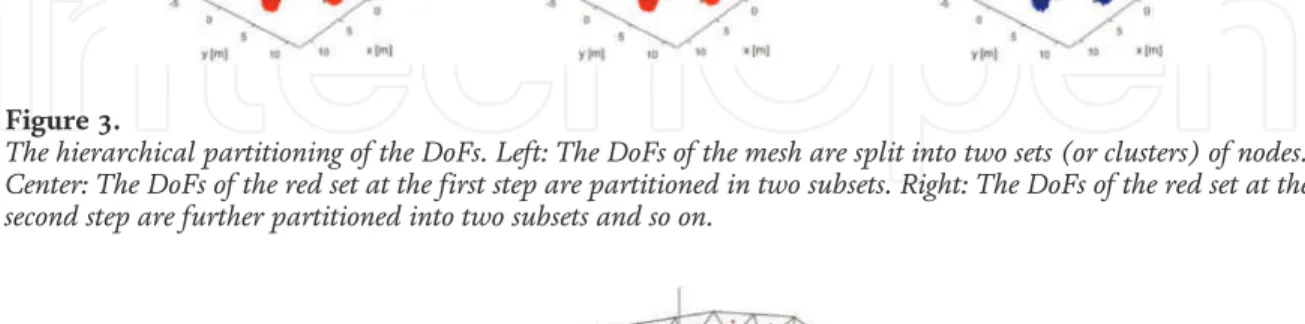
H 2 -matrix representation
The size of the individual regions (given by the diagonal of the parallelepiped bounding the region) occupied by the DoFs is greater than the distance between the barycenter of the clusters. The size of the individual regions occupied by the DoFs is not large enough when compared to the distance between the barycenter of the clusters.
The H 2 -matrix factorization
In the rest of the section, we discuss in detail the factorization of P. Specifically, matrixPis is factorized in the form of a partial LU decomposition [16]. Since most of the blocks in the original matrix are long, they will be effectively compressed by the procedure described above (see [16]).
Numerical results and discussion
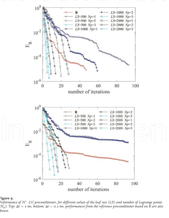
Performance of H2-LU preconditioning, for different values of the leaf size (LS) and the number of Lagrange points (Np). Finally, the accuracy of the preconditioner is shown in Figure 11 for different values of LS, Np and Δt.
Conclusions and future work
Taken together, these numerical results confirm that an efficient iterative solver for the CARIDDI integral model of the eddy current problem needs a preconditioner containing some far-field approximations from the interaction matrix. First perturbation studies and simulations with a view to the development of the physical basis DEMO.
TOP 1%
Introduction
- Plasma
- History of plasma
- Dusty plasma
- Types of dusty plasma
- Formation of dusty plasma in the laboratory
- Acoustic modes
The term "plasma" was originally used by the American scientist Irving Langmuir, who defined it as "a quasi-neutral gas of charged particles exhibiting collective behavior." When the number of ions equals the number of electrons (ni≈ne≈n), a gas is said to be "quasi-neutral", meaning it becomes electrically neutral. The existence of dust particles in plasma has revealed advanced fields for researchers and scientists. Based on the order of many radii and characteristic lengths between interacting particles (rd,λD), plasma with dust particles can be called either "dusty plasma" or "dust in plasma".
Research from recent analysis has shown that these dust particles are fine particles. The mass of the dust particles is considered very important because it provides the inertia which is used to hold the DAW, the pressure of ions and electrons provides the restoring force.
Models and numerical simulations
- Current correlation function
- Normalized longitudinal current correlation function C L ( k , t )
- Parameters and simulation techniques
Thus, in ionized gas there is no possibility of sound waves appearing due to the absence of collision. Coulomb coupling strength (Γ) is defined as the potential energy of interaction between particles and the average kinetic energy of the particles. The Debye scanning power is the ratio of the interparticle distance a (the Wigner Seitz radius) to the DebyeλD length.
The above equation can also be stated in the form of longitudinal and transverse stream correlation functions. The longitudinal stream correlation function describes that the wave propagates in the negative and positive Z-axis directions.
EMD simulation results
- Time-dependent longitudinal current correlation function C L ( k , t ), at κ = 1.4
- Time-dependent longitudinal current correlation function C L ( k , t ), at κ = 2.0 Computational results using EMD simulation have shown in Figures 1 and 2 for
From the six panels in Figure 1, it can be seen that the amplitude and wavelength of LCC CL(k,t) increase with decreasing Г(0.9–0.1). It is also established that with increasing wave number (0, 1, 2 and 3) the amplitude of the longitudinal flow increases. It should be noted that the CL(k,t) value of fork= 2 and 3 shows the maximum sine wave behavior at a lower value of Α from Figures 1a–and2a–c. The sine wave behavior decreases with increasing Α and the damping of the wave increases with increasing time and Τ.
Summaries
Although high-energy physics has been the main driver for the development of the particle accelerators, accelerator facilities have continuously expanded applications in many areas of research and technology. To go beyond the maximum capacity of the LHC, the next generation of circular and linear particle colliders under consideration, based on radio frequency acceleration, will require multi-billion investments. To go beyond the LHC's maximum energy capacity, the next generation of RF-powered colliders under consideration will be among the largest and most complex facilities built on Earth, requiring intensive R&D and multibillion-euro investments.
For example, the long-term goal of the Future Circular Collider (FCC) study hosted by CERN [6, 7] is the design and construction of a 100 TeV hadron collider in a 100 km long tunnel. Another key challenge is the sustainability in terms of the AC wall plug power consumption.
Plasma wakefield
The development and optimization of radio frequency (RF) technology played a key role in this remarkable progress. For example, by improving the efficiency of existing technologies, for example by increasing the efficiency of klystrons [11]. As a result, a positively charged ion channel is formed in the path of the driving pulse.
After the passage of the driver (laser or particle beam), the plasma electrons rush back in, attracted by the transverse restoring force of the ion channel. However, one of the main disadvantages of plasma accelerators is the production of relatively poorer beam quality (higher energy spread and transverse size) with respect to conventional RF techniques.
Solid-state-based acceleration
- Dielectric wakefield acceleration
- Crystal channelling acceleration
- Plasmonic acceleration
- Target normal sheath acceleration
- Solid-state plasma by electron field emission
Semiconductor and metal crystal lattices have been proposed to create a solid-state plasma medium for guiding and accelerating positive particles, exploiting the channeling properties in crystals. Wakefields in crystals can be induced by exciting the high-frequency collective motion of conduction electrons through the crystal lattice (see the next section on plasmonic acceleration). To be effective, the dimensions of the driver must match the spatial (nm) and time (subfemtosecond) scales of the excited plasmonic oscillations.
Unlike plasmonic acceleration, other new solid-state-based acceleration techniques require complete ionization of the ion lattice or ablation of solids, as described in the next section. The field is the size of a laser electric field (TV/m) that ionizes atoms on the surface.
Outlook and prospects
For many years, the development of cheap and compact high-energy particle accelerators and light sources has been the ultimate dream of the accelerator physics community. Some of the most promising new acceleration techniques are briefly reviewed in this chapter. ICFA-ICUIL White Paper, Joint Force: High Power Laser Technology for Accelerators.
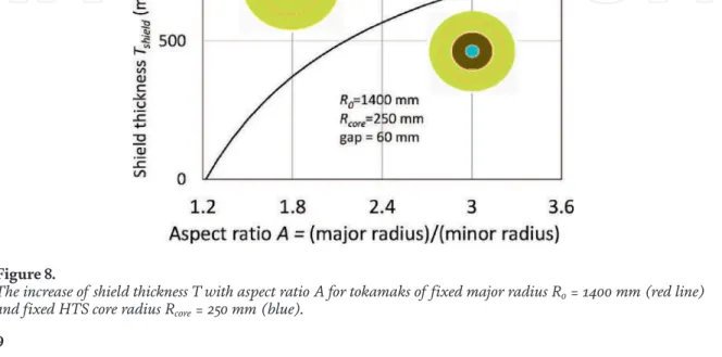
Fusion power is one of the few options capable of providing abundant safe baseline energy to the world [1]. The purple open squares show the thickness of the shield, which increases rapidly from 0.55 m large radius.
The use of modeling codes to optimize spherical tokamak designs
Spherical tokamaks
It is therefore possible to explore the dependence of the tokamak major radius R0 as a function of tokamak aspect ratio and toroidal field at a constant value of the triple product, safety factor and H factor. Much of the remainder of this chapter will explore the materials and mechanisms most appropriate for a fusion tokamak shield. A plasma with higher elongation κ and triangularity ε naturally crushes the plasma so that the orbiting electrons take longer to close the center column and utilize the available field more efficiently.
Another advantage presented by the prospect of a reduced external power drive power plant was the experimental observation of the bootstrap flow driven by plasma pressure gradients, which had been predicted theoretically by Bickerton, Connor and Taylor in 1971 [9] and observed experimentally on the Princeton tokamak TFTR by Zarnstorff et al. The goal was to exploit the dual technologies of spherical tokamaks and high-temperature superconductors.
High-temperature superconductors
This can spread to nearby superconductors and so the magnet shuts down and can be destroyed. The coil has a bore of 300 mm and contains six modular "pancake" coils wound with 738 m of 12 mm wide tapes with variable inter-turn resistance between the tapes and reaches 10 Tesla. The inset shows the predictions of the RACOON code for the coil temperature compared to measurements during damping at the vertical line position.
Research at Tokamak Energy's David Hawksworth HTS Magnet Laboratory has developed a middle ground of partial insulation with precise interwinding resistance between each tape layer to allow current transfer but avoid the time constant problems. It could be extinguished by switching off the current, but the stored energy was dissipated in the magnet in the resistance between windings and there was no system degradation [18].
Shield design explored using “tally tagging”
It shows that most of the indirect neutrons are returned by tungsten atoms further into the shield. At the base of the "waterfall", the neutrons lose further energy by moderating in a gently sloping river bed. The inset shows the energy spectrum of direct neutrons (red top right) and indirect and gamma neutrons (blue bottom left).
At the bottom of the waterfall, moderation gradually reduces the energy (the rocky river bed) until energy is almost completely absorbed by 10B (the sandy river bed). Direct” refers to neutrons originating in the plasma core itself, most from the plasma, some from the outer reflector, both outside the scale of the neutron graph.
Conclusions
These are usually largest near and fall off fairly quickly in the shield layers. Rapid neutron damage will result from the 14-MeV neutron fluence component penetrating the shield. In contrast, gamma damage can be identified as originating from (n,n'-gamma) reactions in 63Cu of the heat sink surrounding the HTS tapes and from 56Fe and 58Ni in the Hastallloy of the HTS tapes. n, gamma) responses of 184W and 182W in the shield are significant but decrease rapidly in the shield.