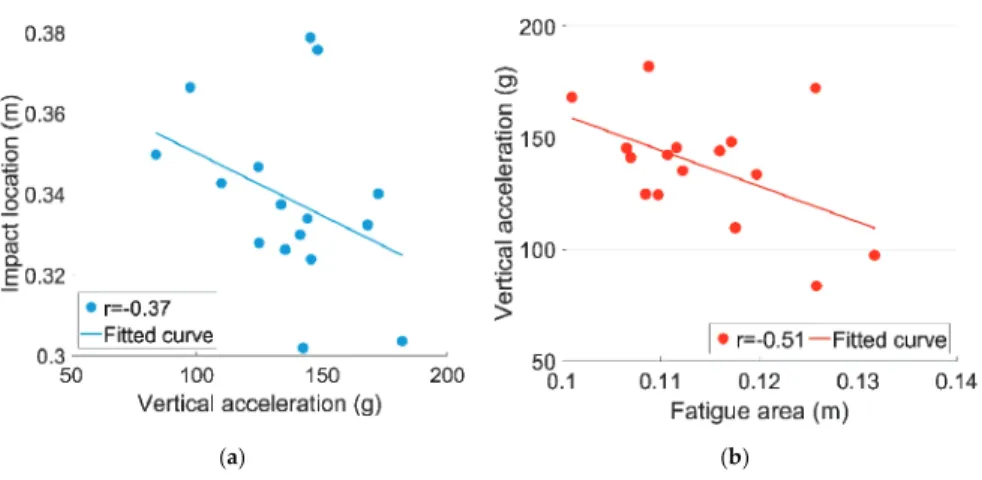
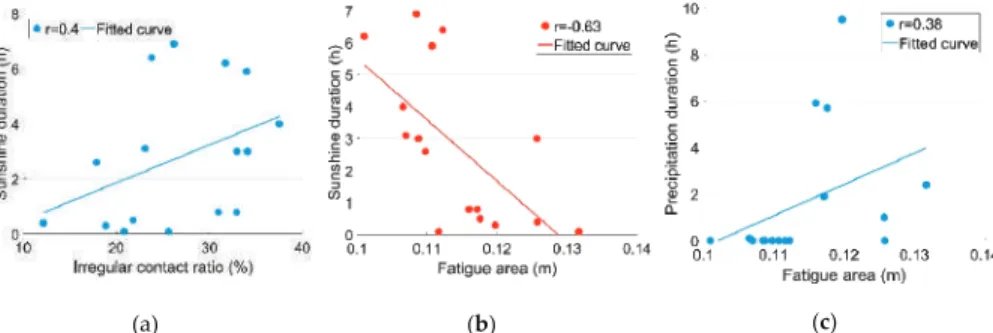
The main data measured is the 3D acceleration responses (i.e. ax, ayandaz)) of the intersection due to the passing trains. In the analysis presented here, the correlations between the dynamic responses of the intersection (a,Ir,LoandFa) and the weather-related variables (Tm,DsandDp) are studied.
Numerical Verification
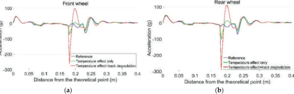
High (moderate/strong) correlation scores between D and dynamic crossing responses clearly indicate the influence of weather. The response of the rail to the vertical acceleration due to passing wheels is shown in Figure 22.

Conclusions and Future Work
It can be concluded that the change in cut-off due to precipitation affects the dynamic performance of the intersection, but the effect of lower fi is not always positive. Numerical analysis of the dynamic interaction between the wheelset and the junction of the switch using the explicit finite element method. Veh.
A Novel Monitoring Approach for Train Tracking and Incursion Detection in Underground Structures
Introduction
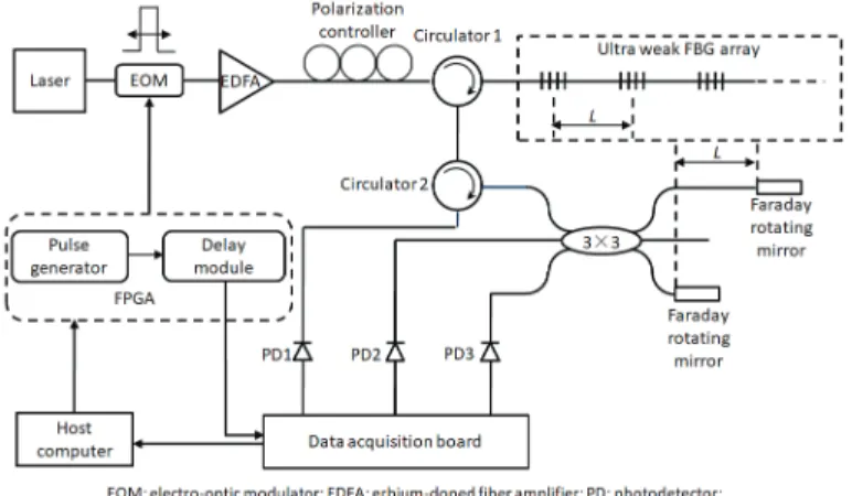
In addition, a multi-parameter measurement system based on an ultra-weak FBG array with sensitive material was proposed in [29]. Finally, the performance in tracking and detecting targets of interest is discussed based on the experimental results presented by the distributed vibration responses of the ultra-weak FBG array.
Sensing and Monitoring Principles
The spatial resolution of the distributed vibration along the sensing optical fiber is typically determined by the parameter L. Here, Faraday rotating mirrors are used in the demodulation process of the ultra-weak FBG array to suppress the polarization effect.
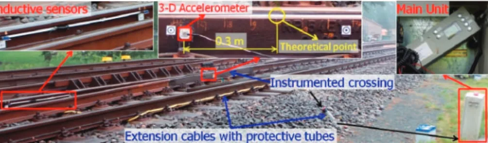
Design and Field Arrangement for the Experiments
Due to the spatial resolution of the sensing optical fiber and the specific layout of the tunnel structure, more than. In addition to observing the response caused by the train traveling in the subway tunnel monitored by the sensing optical fiber, the test discussed the identifiability of the sensing optical fiber on the train moving in the opposite direction in the adjacent tunnel.

Results and Discussion
Figures 9 and 10 show the results of the designed human intervention in the time and frequency domain, respectively. However, the similarity of the distribution features in the different interference cases shown in Figure 12 can still be observed.

Conclusions
The maximum relative error of the autocorrelation method with a sampling rate of 2 ks/s, 5 ks/s is 3.2% and 1.3%, respectively. In the autocorrelation method, only one channel of the electrostatic signal is required.
Measurement Principle and Finite Element Simulation
The calculation errors of the T method and the M/T method mainly come from the number of pulse clock counts (m01−m1,m03−m3). Figure 8a shows the induced charge on the electrode as the tape rotation starts furthest from the electrode, then passes the electrode and finally returns to the initial position. By calculating the difference of the induced charges, we can obtain the current shown in Figure 8c.
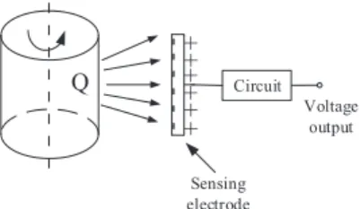
According to the superposition principle of the electric field, the amount of charge Q induced on the electrode with an angular displacement α can be calculated by equation (15). The induced charge on the electrode can be thought of as a weighted average value of the charge's contribution in a sensitive region.
Experiment Results and Discussion
The high signal-to-noise ratio and strong periodicity help to improve the stability of the square wave transformed from the signal, which is very important for the rotational speed calculation based on the square wave. The mean values of the measurement results for the T method and the M/T method are plotted in Figure 18. Figure 21 shows the measurement errors of the digital approximations and the autocorrelation method at sampling rates of 2 ksps and 5 ksps.
To investigate the robustness of the proposed method, the standard deviations of each measurement point are listed in Table 2. The standard deviations of the auto-correlation method in Table 2 contain a number of zero and some other values, which can be easily understood from the principle.
Multi-Factor Operating Condition Recognition Using 1D Convolutional Long Short-Term Network
Experiment and Vibration Signal
As shown in Figure 1, 12 acceleration sensors were applied to the surface of corresponding cylinder heads to monitor the status information of the running diesel engine. The vibration signals formed the basis for the diesel engine's multiple operating status detection. In addition, a hydraulic dynamometer was connected to the output end of the diesel engine to adjust the load.
Since the amplitude of the vibration signal exhibits great randomness, the vibration signal of a diesel engine can be considered as a non-periodic and non-stationary signal. This feature of the vibration signal greatly increases the difficulty of multi-factor operating condition recognition.
Technical Background
- LSTM
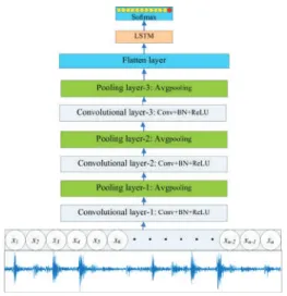
When combustion occurs and the intake valve and exhaust valve close, a noticeable excitation response is generated at the corresponding stage. Mathematically, this can be expressed as shown in equation (1). 1) where the size of the convolution kernel, fijis is the output of the jth neuron of the ith filter in the hidden layer, Φ is the activation function, and biis the overall bias of the ith filter. Meanwhile, it can reduce the number of parameters to prevent overfitting and improve the generalization of the model.
By repeating operations as described above, features can be extracted continuously to improve the generalizability of CNN. A recurrent neural network (RNN) is a kind of neural network that can be used for sequential data analysis, while LSTM is a specific kind of RNN.
Methodologies
In other words, the outputs of the BN are the input of the ReLU activation function. The learning process of 1D-CLSTM for recognizing multi-factor operating conditions is an iterative process. In the training of 1D-CLSTM designed to recognize multi-factor operating conditions, the learning rate was set to 0.001.
After the validation error stops decreasing, the early termination of model training can be applied to the training of 1D-CLSTM. In addition, mini-batch gradient descent and early termination were adopted in the training of 1D-CLSTM to achieve a fast training speed and avoid model overfitting.
Experiments
The 1D LeNet-5, which is a convolutional network that has the same network layers as LeNet-5, that is, two convolutional layers and two fully connected layers. The 1D AlexNet, which is a convolutional network having the same network layers as AlexNet, i.e. five convolutional layers and three fully connected layers. The 1D VGG-16, which is a convolutional network that has the same network layers as VGG-16, with 1D convolutional kernels adopted.
To verify the generalizability of the proposed approach, the designed 1D-CLSTM was applied to a 20-cylinder diesel engine (V20DE), as shown in Figure 12. In general, the measured data of different engine types varies widely and the 1D-CLSTM classifier needs to be trained before use.

Conclusions
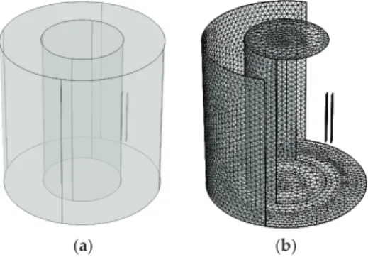
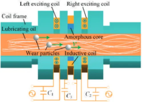
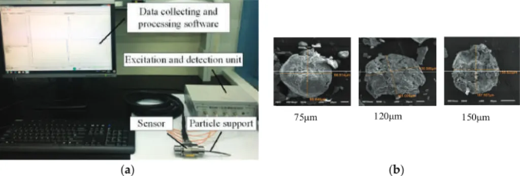
The change in the resistance of the exciting circuit caused by the particles can characterize the sensitivity of the sensor indirectly. It can be seen that the magnetic flux through the inductive coil of the sensor with the amorphous core increases significantly. Here is the outer distance between the exciting coils and is the inner diameter of the sensor.
Raw sensor signal, (b) pre-extracted particle signal, (c) degraded particle signal, and (d) formed particle signal. The theoretical peak-to-peak value of the particle output signal emitted by the sensor is 10 mV.
Experiment
Taking the proposed sensor as an example, Figure 10 shows the raw sensor signal caused by a 120μm diameter particle. Furthermore, after signal shaping, residual interference is further removed, and particle signals with different velocities can be effectively extracted. Figure 12 shows the output signal of the sensors caused by different sizes of ferromagnetic particles.
However, for the proposed sensor, the signal amplitude of the particle with the diameter of 75μm reaches 2.6 mV, which is much larger than that of the conventional sensor. A comparative analysis of the detection result of the conventional sensor and the proposed sensor with various resonant capacitances is presented in Figure13.
Conclusions
Oil debris signal extraction using integrated improved empirical decomposition and correlated reconstruction. Goal. Improving the sensitivity of an inductive pulse sensor for detecting metallic wear debris in lubricants using the parallel LC resonance method. A joint time-invariant wavelet transform and kurtosis approach for improving in-line oil spill sensor capability.Smart Mater.
Improving Oil Debris Sensor Capability by Reliable Debris Signal Extraction via Wavelet Domain Targeting and Interference Signal Tracking. Measurement. Improving the Wear Particle Monitoring Capability of Oil Waste Sensors Using a Maximum Overlap Discrete Wavelet Transform with Optimal Decomposition Depth.Sensors.
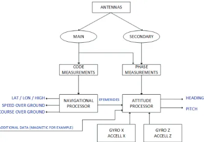
Analysis of Satellite Compass Error’s Spectrum
Materials and Methods
Most of the changes in the heading shown in the image occur due to the behavior of the ship, so they are very similar to each other. This is visible in Figure 11 in the form of a break in the recording of position data due to random interference of the satellite signal. The first records for the compasses used in this part of the experiment are shown in Figure 12 for the Furuno compass and Figure 13 for the Novatel compass.
An example of the behavior of the advanced navigation compass in the case of complete obscuration of the satellite signals (667 s after the start of the recording) is shown in Figure 16. The measuring instrument used in the experiment was placed on a DWF 300 series tramcar and pulled behind a tram [22].
Results
The spectrum of this record is significantly different from others, which is no doubt caused by these four distinctly distorted parts. These oscillations are caused by changes in the set of tracked satellites and the satellites included in the calculations. For moving objects, oscillations occur due to changes in the orientation of the vehicle, as well as unpredictable changes that occur due to the blocking of the satellites by obstacles in the environment.
Discussion
This statement is confirmed by the analysis of the behavior of the devices at the time of signal obstacles. This kind of effect also appears in the coordinate indications referenced by the GNSS receiver, which is a separate part of the tested device. This raises the question of whether the complete reliance of navigation systems solely on a satellite compass in terms of heading is legitimate.
As a result, integrated systems are created, the measurement properties of which depend mainly on the structure of the data processing algorithm. The experiments presented here focused mainly on the frequency spectrum that appears in the recorded results of direction measurements by satellite compasses.


![Figure 20. (a) Temperature-initiated rail lateral displacement in FE simulation (adapted from Figure 11.15 in [23]); (b) the monitored crossing.](https://thumb-ap.123doks.com/thumbv2/1libvncom/9201074.0/16.723.106.617.654.849/figure-temperature-initiated-lateral-displacement-simulation-monitored-crossing.webp)