Inquiries about the use of the book should be directed to INTECH rights and permissions department ([email protected]). In the present chapter, progress in PECS for transparent Al2O3 as well as others has been discussed.
Fundamentals on PECS
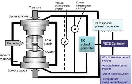
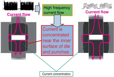
The PECS process is characterized by the use of the pulsating electric current during sintering. Usually, the measured temperature at the surface of the mold (die temperature) is lower than the temperature of the sample (sample temperature).
Sintering of transparent polycrystalline alumina
However, polycrystalline Al2O3 ceramics are mostly opaque due to light scattering from pores and grain boundaries, as well as impurities. Recently, fine-grained transparent polycrystalline Al2O3 has attracted much attention for its superior mechanical and optical properties.
Transparent polycrystalline Al2O3 has increasingly become the focus of recent research mainly due to their unique combination of properties. After Coble developed transparent polycrystalline Al2O3 [42], many studies on the production of transparent polycrystalline Al2O3 by sintering techniques have been reported.
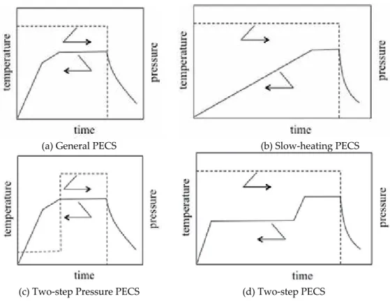
Two-step PECS for transparent polycrystalline alumina
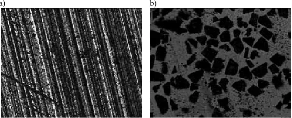
In particular, the elimination of initial particle agglomeration is also very important in PECS for structural ceramics and transparent ceramics. Optical microscope image of the interior of transparent Al2O3 prepared by TS-PECS.
Summary
The bending strength of the samples is about 400 MPa, which is comparable to any commercially available opaque Al2O3. The microstructure of the black dots implies that the black dots are derived from the agglomeration of the original particles of the Al2O3 powder.
Acknowledgements
Even with high pressure PECS, powder properties such as agglomeration are very important.
Author details
88] An L, Ito A, Goto T, Two-step Pressure Sintering of Transparent Lutetium Oxide by Spark Plasma Sintering, J. 106] An L, Ito A, Goto T, Fabrication of Transparent La2Zr2O7 by Reactive Spark Plasma Sintering, Key Eng.
Spark Plasma Sintering of Negative Temperature Coefficient Thermistor Ceramics
Introduction
110] Spina G, Bonnefont G, Palmero, Fantozzi G, Chevalier J, Montanaro L, Transparent YAG obtained by plasma spark sintering of co-precipitated powder. 111] Chesnaud A, Bogicevic C, Karolak F, Estournes C, Dezanneau G, Preparation of translucent oxyapatite ceramics by combined use of lyophilization and spark plasma sintering, Chem.
Theoretical aspects of spark plasma sintering
In addition to Joule heating due to electric current and pressure-induced plastic deformation, SPS also generates a DC pulse voltage between the powder particles and effectively utilizes the spontaneous heat generated by the discharge between the powder particles, which results in some special characteristics. Compared to conventional sintering, SPS has two important features. The SPS process can cause the high-energy pulse to focus on the grain junction, saving energy. 2) The high-energy, low-voltage pulse current of the spark momentarily creates a spark plasma and causes a high localized temperature of several to tens of thousands of ◦C between the particles, which then causes optimal thermal diffusion and grain boundary migration, i.e.
Application of spark plasma sintering in NTC thermistor ceramics
- Brief introduction of NTC thermistors
- Spark plasma sintering and electrical properties of YCr 1-x Mn x O 3 NTC ceramics
Temperature dependence of electrical resistivity ρ of 0.4MgAl2O4-0.6YCr0.5Mn0.5O3 samples sintered by conventional sintering (CS) and SPS [12]. Temperature dependence of electrical resistivity ρ of 0.4MgAl2O4-0.6YCr0.5Mn0.5O3 samples sintered by conventional sintering (CS) and SPS [12].
Summary
Wu, Synthesis of YCrO3 ceramics through a field-assisted sintering technique, Journal of Materials Science: Materials in Electronics. Park, Fabrication and Electrical Properties of Mn-Ni-Co-Cu-Si Oxides with Negative Temperature Coefficient Thermistors, Journal of the American Ceramic Society.
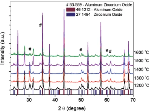
O 3 and O 3 -ZrO 2 Fibers Obtained by Biotemplete with Low Thermal Conductivity
- Methodology
- Characterization
- Results
- Conclusions
Analysis of thermal conductivity by laser flash method of the Al2O3 and Al2O3-ZrO2 porous bodies. In the literature, very little data is available on the thermal conductivity of the Al2O3 and ZrO2 system.
Sintering with Additives
The New Generation of Diamond Wheels with Vitrified (Ceramic) Bonds
Experimental section
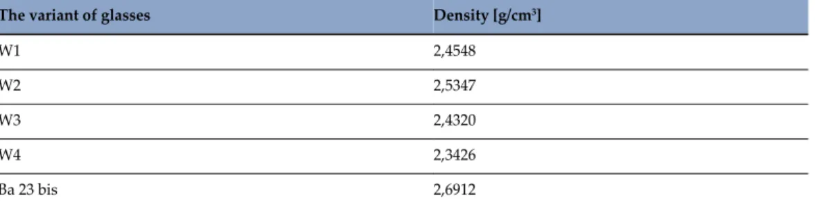
- Part I Preparation and study of some physical and mechanical properties of glasses 1. The starting materials and methods of research
- Part II Operational tests of grinding wheels containing the newly developed glass 1. The starting materials and methods of research
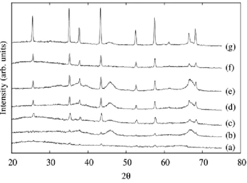
Verification of the existence of these compounds in the glass was carried out on the basis of X-ray examination. The bending of the curve reported that at 542oC there was vitrification and at 649.8oC the softening process began. The photo below shows the test position, wheel and associated components (fig. 10b).
Operational tests of grinding wheels containing the newly developed glass The starting materials and methods of research
Summary and conclusion
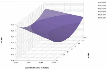
It was observed that the most favorable results were obtained during the processing of samples of the BNDCC composition - the grinding depth of 0.005 mm/double stroke of the table and the peripheral speed of the wheel 15 m/s;. Plichta J, Nadolny K., Pluta J.: Study of grinding efficiency of CBN grinding wheels with increased porosity of spherical corona micrograins. Sitarz M., Leśniak M., Gasek K., Jeleń P.: Effect of SiO2/Al2O3 ratio on the structure and microstructure of glasses from SiO2–Al2O3–CaO–MgO–Na2O–.
An Overview of Densification, Microstructure and Mechanical Property of Additively Manufactured
7] Staniewicz-Brudnik B., Plichta J, Nadolny K.: Effect of porous glass-ceramic materials Addition on properties of cubic boron nitride (cBN) tools. 11] Houy G.: The effect of porosity on the grinding performance of vitrified diamond grinding wheels for PCD blades Ceramics International 2012, http: // dx doi.org/. 12] Procyk B, Staniewicz-Brudnik B., Majewska-Albin K.: Investigations of wettability and reactivity in glass/carbon and glass/ceramic systems.
Ti-6Al-4V — Comparison among Selective Laser Melting, Electron Beam Melting, Laser Metal Deposition and
Preliminary knowledge: Fundamental properties of Ti-6Al-4V and conventional PM Ti-6Al-4V
- Densification of PM Ti-6Al-4V and typical microstructure and mechanical property
- Ti-6Al-4V: Basic physical and mechanical properties
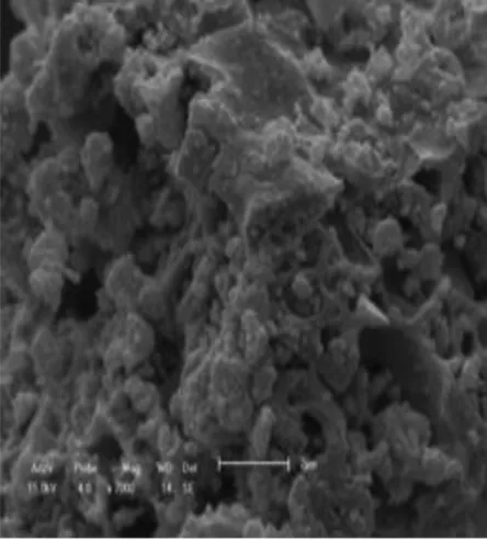
Sintering Mechanism: The sintering/densification of conventional PM Ti-6Al-4V is usually done by solid state sintering. The breaking strength of PM Ti-6Al-4V is comparable or even higher than that of the forged material (ASTM B348) [9]. The breaking strength of PM Ti-6Al-4V is comparable or even higher than that of the forged material (ASTM B348) [9]. a) Scanning electron microscopy (SEM) image to show the typical microstructure of PM Ti-6Al-4V [25] and (b) ductility of PM Ti-6Al-4V as a function of oxygen [26].
![Figure 1. (a) Scanning electron microscopy (SEM) image to show the typical microstructure of PM Ti-6Al-4V [25] and (b) ductility of PM Ti-6Al-4V as a function of oxygen [26].](https://thumb-ap.123doks.com/thumbv2/1libvncom/9201626.0/84.765.94.669.126.355/figure-scanning-electron-microscopy-typical-microstructure-ductility-function.webp)
Various AM approaches for Ti-6Al-4V and their key processing parameters
- Selective Laser Melting (SLM)
- Electron Beam Melting (EBM)
- Laser Metal Deposition (LMD)
- Selective Laser Sintering (SLS)
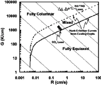
Arcam supplies a range of EBM machines for processing Ti and Ti alloys, including Arcam A1, A2, S12 and S400, and it currently dominates the market [47–66]. A variety of LMD machines and laser systems are being used to fabricate metals and alloys, including Ti-6Al-4V, such as LEMS TM Nd:YAG, Trumpf HLD 3504 Yb:YAG and IPG with Yb fiber laser [67-78]. The general working conditions and important machine/processing parameters are shown in Figure 5 and listed in Table 6.
![Table 2. Mechanical properties of Ti-6Al-4V achievable via forged- then-annealed [14,15,27,28]](https://thumb-ap.123doks.com/thumbv2/1libvncom/9201626.0/86.765.160.609.122.416/table-mechanical-properties-ti-al-achievable-forged-annealed.webp)
Densification of AM Ti-6Al-4V
- As-built density of AM Ti-6Al-4V
- Densification of SLS Ti-6Al-4V: Solid state sintering and liquid phase sintering The fact that the as-built density of the SLS Ti-6Al-4V is similar to that of the conventional PM
- Densification of EBM, SLM, and LMD Ti-6Al-4V: Solidification from liquid
SLS Ti-6Al-4V is unique in this conclusion, with as-built densities around 95% and similar to the as-sintered density of the conventional PM Ti-6Al-4V [4-13]. This further suggests that the driving force and activation energy for densification of the conventional PM Ti-6Al-4V should be applicable to SLS Ti-6Al-4V. The so-called time-temperature transformation (T-T-T) of Ti-6Al-4V regulates phase selection and phase constitution of the solidified microstructure.
![Figure 6 summarises reports on as-built density of the AM Ti-6Al-4V using LMD, SLM, EBM, and SLS [29-88]](https://thumb-ap.123doks.com/thumbv2/1libvncom/9201626.0/90.765.194.570.577.884/figure-summarises-reports-built-density-using-lmd-slm.webp)
Microstructure of AM Ti-6Al-4V (As built)
- Microstructure of SLS Ti-6Al-4V
- Martensite phase transformation
In this case, the much faster cooling rate in the surface of the AM Ti-6Al-4V contributed to the formation of the. Optical microscopy images of the EBM Ti-6Al-4V from the (a) cross-section and (b) longitudinal cross-section. SEM images of the LMD Ti-6Al-4V showing heterogeneity between (a) the surface of the alloy (lamellar with martensite phases) and (b) base/bulk material [71].
Mechanical property of AM Ti-6Al-4V (As built)
Heat treatment of AM Ti-6Al-4V and corresponding microstructure and mechanical properties
- Heat treatment temperature: A collection from AM Ti-6Al-4V and corresponding mechanical property
- Stress relief annealing and corresponding microstructure of as-annealed AM Ti-6Al-4V Heat treatment at temperatures below the temperature of the martensite phase transformation
Most of the performed AM Ti-6Al-4V therefore require heat treatment to mitigate the effect of residual stress on the performance of mechanical properties. Such heat treatment can only offer stress relief to reduce the residual stress in the fabricated AM Ti-6Al-4V. It should be noted that the heat treatment can roughen the α AM Ti-6Al-4V colony, see Fig. 2b.
![Figure 14. (a) UTS and (b) elongation of as-built Ti-6Al-4V prepared by the various AM techniques [29-88]](https://thumb-ap.123doks.com/thumbv2/1libvncom/9201626.0/96.765.224.539.277.494/figure-uts-elongation-built-ti-prepared-various-techniques.webp)
Potential oxygen issue for the AM Ti-6Al-4V and counter measurements
- Oxygen equivalent and oxygen level in AM Ti-6Al-4V
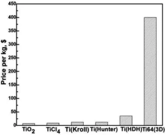
- Price issue of raw AM powders
- Counter measurements
However, the high cost of ELI raw powder can be a problem for AM Ti-6Al-4V from a cost perspective. High cost may be a problem bottleneck for AM Ti-6Al-4V to be fully adopted by the industry. When using powders with a high impurity (oxygen) content to develop AM Ti-6Al-4V, countermeasures must be taken into account.
Concluding remarks
Microstructure and tensile properties of selectively laser-melted and HIPed laser-melted Ti-6Al-4V. Elevated temperature characterization of electron beam free mold made Ti-6Al-4V and dispersion strengthened Ti-8Al-1Er. A comparative study of laser direct metal deposition characteristics using gas and plasma atomized Ti-6Al-4V powders.
Metal Matrix Composites Added of Nanostructured Tantalum Carbide
- Synthesis of nanostructured carbides — TaC
- Eurofer steel — Complexity microstructure and property
- Metal matrix composite — MMC with ceramic reinforcement
- High-energy milling — Reinforcement by dispersing nanoparticles into the matrix
- Sintering
- Experimental procedure
- Results
- Results
- Conclusions
The use of the Powder Metallurgy (PM) technique in the production of MMC composites is increasing. In addition, the distribution of tantalum carbides in the metal matrix of EUROFER steel was observed. In the case of the commercial TaC-reinforced composite, there is a significant difference, which can be related to the trans-phase.
Sintering Techniques on Metals
Consolidation of AISI316L Austenitic Steel — TiB2 Composites by SPS and HP-HT Technology
Materials and research methodology
- Materials selected for sintering composites
- Fabrication of composites
- Testing methods
An improvement was obtained in the Young's modulus (218 GPa), tensile strength (885 MPa) and compressive strength (1800 MPa) of the sintered materials. In the case of the HP-HT method (Figure 14a) it was found that microhardness is essentially dependent on the sintering temperature. A homogeneous distribution of the reinforcing TiB2 phase was obtained in the matrix of all the sintered products.
Correlation between Thermal and Electrical Properties of Spark Plasma Sintered (SPS) Porous Copper
Experimental
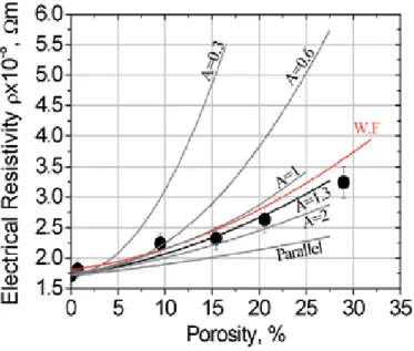
Thermal conductivity (κeff) values were calculated using the equation κeff=α ρ Cp, where α is the thermal diffusivity, Cp is the specific heat (measured by differential scanning calorimetry, STA 449- Netzsch), and ρ is the bulk density of the sample. Values of the electrical resistivity and thermal conductivity measured at room temperature as a function of porosity are shown in fig. As expected, a general trend was observed to increase the electrical resistivity and decrease the thermal conductivity values with increasing porosity amount.
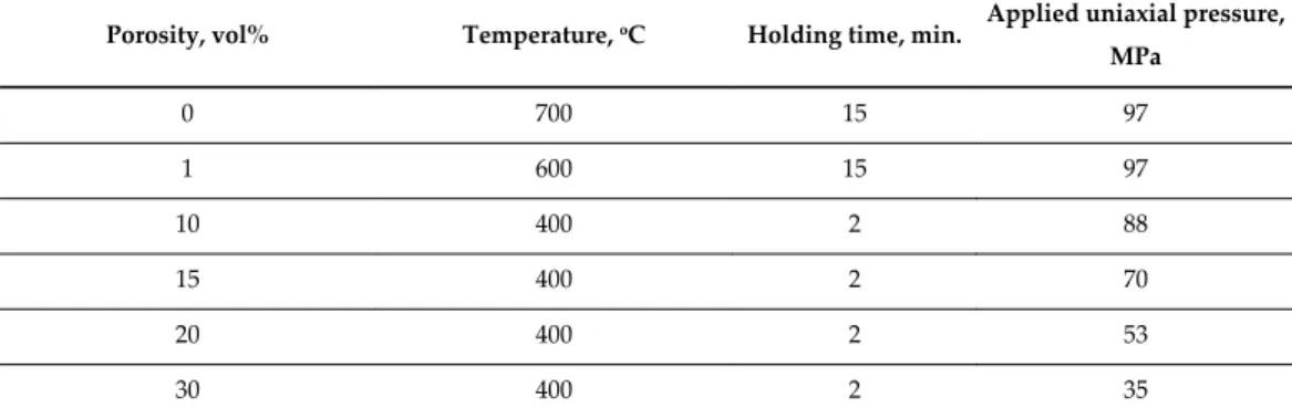
Discussion
- General Effective Media (GEM) theory
- Weidemann-Franz (W.F.) relation
These values were used for the calculation of the transport properties for the entire investigated samples, which show different porosity amounts. The calculated values of the transport properties as a function of the porosity levels using Weidemann-Franz relationship (eq. 3) are also shown in Fig. 4-5 presented. Such an approach cannot provide any insight into the geometric alignment and morphology of the pores.
Conclusions
Applying the GEM equation proved to be the ideal approach for estimating the thermal and electrical properties of porous materials, due to its ability to provide a good approximation of the dependence of the porosity quantity on the electrical and thermal conductivity for a given porosity quantity, in addition to some insight about the alignment, distribution and morphology of porosity. 1 Department of Materials Science, Ben-Gurion University of the Negev, Israel 2 Department of Mechanical Engineering, Ben-Gurion University of the Negev, Israel 3 Institute of Applied Mechanics, Clausthal University of Technology, Clausthal-Zellerfeld, Germany. Koh and Anthony Fortini, "Prediction of thermal conductivity and electrical resistivity of porous metallic materials", Int.
Ram Extrusion and Hot Sintering of Reprocessed PTFE
Recycling of Polytetrafluoroethylene (PTFE) Scrap Materials
Plastics
PTFE
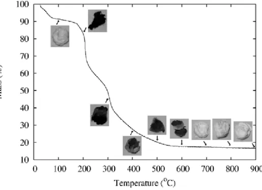
PTFE can withstand a wide temperature range (-184°C to 260°C) and is used in cold as well as hot environments. Above 500°C, when heated in air, PTFE disappears completely due to the production and release of carbon and fluorine in the form of CO2 and fluorine gases into the atmosphere [1]. PTFE is insoluble in common solvents and is resistant to almost all acids and bases.
Filler grade PTFE
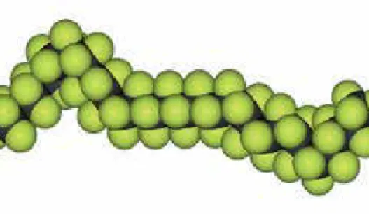
PTFE repels everything and therefore no molecules can stick to the PTFE surface, making it slippery (Fig.2).
Recycling PTFE scrap material
To avoid this, Environmental Protection Agencies have taken an action to recycle all the PTFE material. One involves irradiating the PTFE waste to a heavy dose of ionizing radiation that will reduce its molecular weight. The second method involves pulverizing the PTFE waste without radiation so that it becomes reusable like virgin PTFE itself.
Irradiation stability of PTFE
- PTFE Micropowder
The scattering angle of an individual particle is inversely proportional to the particle size. Figure 7 shows that an average particle size of 0.26 µm was obtained by electron irradiation of waste PTFE followed by grinding, which was achieved by either a jet mill or a hammer mill. The flocculent morphology of the imported waste powder shown in Figure 8 provides better lubrication properties of the micro powder.
![Table 1. Radiation Stability of thermoplastic polymers [3]](https://thumb-ap.123doks.com/thumbv2/1libvncom/9201626.0/175.765.88.678.123.672/table-radiation-stability-of-thermoplastic-polymers.webp)
Reprocessing of unirradiated PTFE scrap
- PTFE has different grades Grade A: 100% virgin material
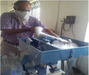
- Issues to be tackled in manufacturing reprocessed PTFE powder are the following i. Difficulties in grinding the scrap into a fine powder
- Grinding PTFE scrap - Kirk-othemer encyclopedia of chemicals
Although off-white recycled PTFE has certain advantages over pure PTFE, namely low creep and better mechanical strength. High purity processed PTFE is white in color similar to base PTFE and is used for application. Agglomeration and sintering of waste dust during thermal annealing caused cracks in the recycled PTFE billets during atmospheric pressure sintering.
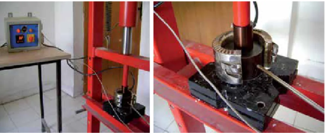
Compression molding
- Sintering treatment
Instead, after cold pressing in the press, the die itself and the piston with the PTFE disc inside were held in the high capacity air under mechanical pressure. The cold-pressed pellet together with the die and the stamp are put under pressure using a C-clamp. High pressures with clamps not only discolor the pills, but also fuse them to the mold.
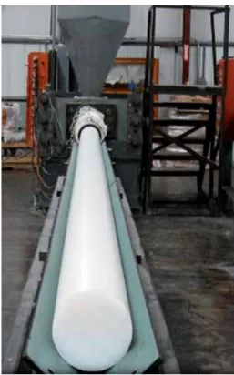
Ram extrusion
The extrusion pressure ranges from 26 to 74 MPa depending on the length of the cold zone above the hot section of the cutting tube and the extrusion speed is 3 m/h. This conclusion was confirmed when the color reduction in subsequent baking at 400 ° C for 1 hour in an air oven, which led to the escape of carbon into the atmosphere in the form of carbon dioxide gas. Fluorine being a gas produced by the decomposition of fluorocarbon has probably already escaped during sintering while carbon in the absence of oxygen has been deposited inside the ingot.
![Figure 5. XRD patterns of the SPS-sintered YCr 1-x Mn x O 3 ceramics [32].](https://thumb-ap.123doks.com/thumbv2/1libvncom/9201626.0/37.765.190.581.119.457/figure-xrd-patterns-sps-sintered-ycr-mn-ceramics.webp)