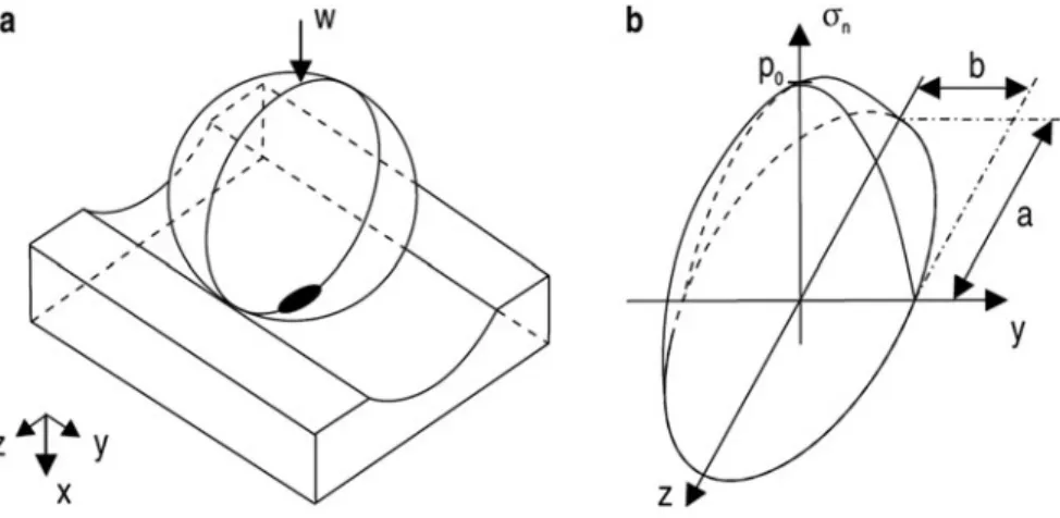
Some of the main phenomena affecting the nonlinear dynamic behavior of bearings are discussed in the following subsections. The dimensions of the contact area are small compared to the radii of curvature of the contacting bodies.
Influence of the Lubricant Film
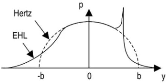
The main stresses occurring below the center of the contact area have been calculated by Jones (1946). An EHL movie is generated, which modifies the pressure distribution at the input and output regions of the contact.
Durability
Due to the strong interaction between the EHL film and the deformation of the contacting surfaces, the lubricant film affects the stiffness and damping characteristics of the bearing. Solid particles originate for example from the grinding process of the bearing and/or its surrounding structure (carbide pile).
Non Torque Loading
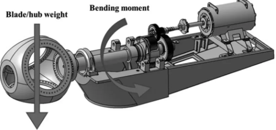
Effect of external dynamic loads For bearings subjected to highly fluctuating loads, recent research highlights a strong reduction of the actual bearing life w.r.t. With carrier-bearing clearance, the shaft deflection moment is transmitted into the gear masks and planet bearings.
Numerical Modelling of Bearings
- Overview of State-of-the-Art Bearing Models
- Two-Dimensional Bearing Models
- Three-Dimensional Bearing Models
- Ball Bearings
- Roller Bearings
- Bearings with Distributed Flexibility
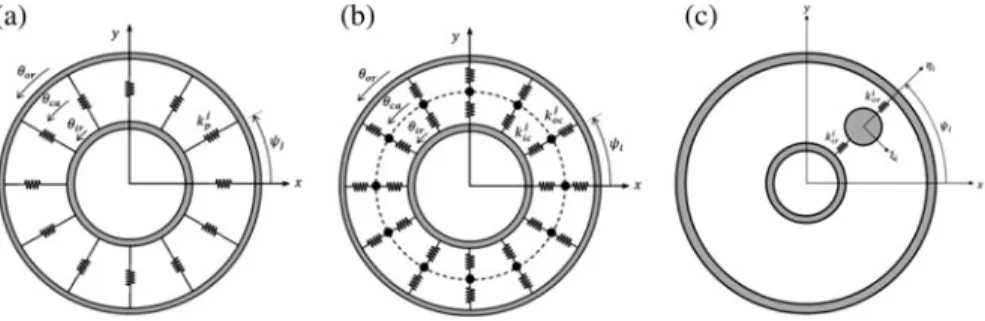
A second distinction is based on the level of complexity and detail included in the bearing's flexibility description. In paragraphs it is assumed that the (elastic) deformation of the bearing is limited to the contact zones within the bearing (i.e. the areas over which contact takes place between the rolling elements and the inner and outer raceways). Inclusion of the influence of elasto-hydrodynamic lubrication (EHL): lubrication reduces friction and wear in the contact interactions between rolling elements and raceways.
The rolling elements and the inner and outer rings move only in the plane of the bearing. One of the distinguishing features of the various plain bearing models is the way in which the contact interactions and inertial properties of the rolling elements are modelled. In this case, all dynamic effects resulting from the movement of rolling bodies (i.e. inertial and centrifugal forces) are neglected.
Furthermore, a study of the influence of centrifugal effects is included in Liew et al. Consequently, the global (or bulk) deformations, such as the bending of the bearing housing, cannot always be ignored.
Conclusions: Towards Unified Wind Turbine Gearbox Models
The multitude of static shape vectors is replaced by a relatively small set of global constraint modes to capture the effect of the bulk flexibility of the rings, supporting structure and the mounting conditions on the behavior of the bearings. 2015b) that by choosing an appropriate basis for the B-splines, the interaction surface can be constructed by a linear combination of the control points, using the modal participation factors (or reduced elastic coordinates) of the affected mode shapes during simulations. The literature on gear modeling and analysis is as rich as that for bearings and it is beyond the scope of this chapter to provide a detailed review.
Although modeling individual components can be interesting for solving local problems in a wind turbine gearbox, they are rarely sufficient to draw conclusions about the behavior of the entire power train. The inherently different interface behavior of the modeling strategies makes it difficult to create a single powertrain model that is scalable to different levels of complexity depending on the intended use. Modern linear and non-linear model order reduction techniques are one of the main areas of research that could benefit wind turbine powertrain modelling.
Sections 9.1-9.3 summarized a few key points of focus regarding drivetrain modeling in a wind turbine context with specific focus on the state-of-the-art in bearing modeling. Acknowledgments The authors would like to thank the European Commission for their support of the MAREWINT research project (GA 309395).
Introduction and Motivation
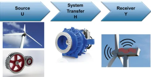
By identifying the origin of each of the phenomena of interest, it is possible to understand where corrective action should be applied to increase the system NVH performances. This approach will objectively quantify the agreement between the design assumptions and the behavior of the actual structure. Experimental Modal Analysis relies on measurements of the system response at the receiver (i.e. acceleration) due to the measured inputs at the sources (typically forces) to identify a System Transfer Function that represents the dynamics of the system itself.
However, the main forces acting on the gearbox during operation occur at discrete frequencies that are multiples of the base rotational speed. Since one of the assumptions of operational modal analysis is about the broadband force spectrum, it is clear that the identification of the modal model under stationary conditions is practically infeasible for a gearbox where the harmonic density is such that hardly any mode is visible (Manzato et al. 2013). The orders can then be considered representative of the systemic transmission (Figure 10.1) and modal parameter identification techniques can be applied.
The method was first introduced several years ago as Order-based Modal Analysis (Janssens et al.2006) and was further developed and validated recently. In this section, the concept of the method will be reviewed, with particular focus on the techniques needed to derive orders that can be successfully used for modal analysis.
Order Tracking Techniques
- Time Domain Sampling-Based Fast Fourier Transform Order Tracking
- Angle Domain Resampling Order Tracking
- Time Varying Discrete Fourier Transform (TVDFT)
- Vold-Kalman (VK) Filter-Based Order Tracking
Finally, the order amplitude and phase are extracted from the FFT spectra. The end result of the technique is that the uniform t data becomes uniformly distributed angle data (Figure 10.3). The advantages of resampling order tracking are leak-free order estimates that fall on spectral lines, as well as order resolution that is constant with respect to width.
The method retains most of the advantages of resampling-based order tracking and can be implemented in a very efficient way without the computational burden and complexity of the time-domain to angle-domain transformation. This method extracts the time history of the order and an estimate of the amplitude and phase of the same order. 34; (n) is introduced on the right-hand side of Eq. the current frequency of the sine wave.
The second equation in the VK method is the so-called dataalign. 10.8) and describes the relationship between the order x(n) and the measured data y(n). This value determines the tracking characteristic of the filter and is calculated according to Eq. 10.9) as the ratio of the standard deviations of the structure and data equations:.
Order-Based Modal Analysis
Normally, the measured data is a combination of all the orders generated in the machine plus a random noise component. Choosing large values leads to a very selective filtering in the frequency domain; on the contrary, small values will decrease the frequency resolution obtaining faster convergence. Applying the ratio as a weighting function and combining the previous two equations, the system in Eq. 10.10) for all observed time samples will yield a global system of overdetermined equations for the desired waveformx(n) that can be easily solved by standard least-squares techniques.
When using these spectra in standard OMA, the algorithm will mistakenly identify them as physical poles; In addition, they can hinder accuracy in estimating modes at nearby frequencies. In this formulation, the ramp-up or decay is then treated as an excitation with multiple sinusoidal shifts in the frequency band of interest. 2LRCUR (10.13), where LR and UR are real-valued lower and upper residuals used to model the effects of modes outside the considered frequency band. V and Lare mode shape matrix, a diagonal matrix containing complex poles and mode participation factors.
Displacement orders are proportional to the square of the rotational speed and, as a consequence, acceleration orders are proportional to the fourth power of the same rotational speed. The main difference is that in the classical modal analysis the acceleration FRFs are proportional to the squared frequency axis.
Dynamic Characterization of Operational Gearboxes
- Operational Modal Analysis
- Order-Based Modal Analysis
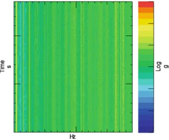
3 optical sensors (zebra tapeC laser) were respectively installed on the Low Speed Shaft and on the High Speed Shaft of each of the two gearboxes in the test rig. The response data obtained during the acceleration measurement was also collected and the gearbox signature during constant speed operation is shown in Figure 10.5. The results can then be considered as an average over time of the frequency response as shown in Figure 1.
Once the tacho is fixed, order tracking can be applied using one of the techniques described in Sect.10.2 and the orders of interest extracted. As an example, comparing Fig. 10.9 the cross-power spectrum and the 1st order of the high-speed gear stage sequence (1st gear mesh frequency of the high-speed stage) for the same channel over the same frequency bandwidth. The results are summarized in Fig. 10.10, where the relative variations of the natural frequencies for the 3 cases (using as reference load case the one with 100% load) are shown.
The general trend of the results shows an increase of the natural frequencies with the torque value. One way to validate the identification results is to compare the measured sequence with the one calculated using the modal parameters in the parameterization of the system transfer given in Eq.
Conclusions
In addition, damping information for each mode can be extracted and closely spaced modes can be separated as soon as order resolution allows. In addition, using more advanced order tracking techniques, although sometimes computationally demanding, can significantly improve results. The additional effort compared to the ODS calculation is limited, although Vold-Kalman order tracking is computationally more demanding and the quality of the tacho signal must be high enough to allow reliable data processing.
The results of the proposed approach were used in Vanhollebeke et al. 2015) to validate the operational response of the analyzed gearbox predicted using a flexible multibody model. In: Abstracts of the IMAC-XXIV: conference and exposition on structural dynamics – looking forwards: technologies for IMAC, Society for Experimental Mechanics, St. In: Allemang R, De Clerck J, Niezrecki C et al (eds) Topics in modal analysis volume 7: proceedings of the 31st IMAC, a conference on structural dynamics, 2013.
Proceedings of the Society for Experimental Mechanics Conference Series, Springer, New York Manzato S, Di Lorenzo E, Medici A et al (2015) Custom-based modal analysis versus standard techniques for extracting modal parameters of operational wind turbine gears . In: Mains M (ed) Topics in modal analysis volume 10: proceedings of the 33rd IMAC, a conference and exhibition on structural dynamics, 2015.
Tower & Support Structure