The function of the spark gap is to protect the transformer when the surge arrester fails. The purpose of the spark gap was to act as backup protection when the arrester fails.
INTRODUCTION
- Background to the Dissertation
- Literature Review of Works Produced On Spark Gaps
- Objectives of the Dissertation
- Dissertation Outline
The literature review also discusses the performance of the transformer insulation when exposed to lightning impulse voltage. The simulation studies investigate factors that have an impact on the reliability of the proposed protection scheme. f) The laboratory experiments used to verify the results of the simulation studies and confirm the choice of gaps and gap settings are then presented.
THE HISTORY AND THEORY OF SPARK GAPS
Introduction and history of Spark Gaps
Rogowski [31] started with an analytical solution of the field due to a finite plane plate parallel to an infinite plane. This ensures that the spark point is at least 2D away from the lower end of the upper insulator.
![Figure 2.1 Open Spark Gaps, Kreuger [47]](https://thumb-ap.123doks.com/thumbv2/pubpdfnet/10631737.0/16.892.349.567.441.658/figure-2-1-open-spark-gaps-kreuger-47.webp)
The advantages and disadvantages of using Spark Gaps
- Volt-time Characteristics of Spark gaps
- Theory of time lags for breakdown characteristics
If flashover occurs at the front of the wave, the f1ashover point gives a point on the V-T curve. If the over-ignition occurs just at the peak value of the wave; this gives another point on the V-T curve.
![Figure 2.7b Steep chopped wave by rod gap, Kreuger [47]](https://thumb-ap.123doks.com/thumbv2/pubpdfnet/10631737.0/27.892.160.810.493.863/figure-7b-steep-chopped-wave-rod-gap-kreuger.webp)
Concluding remarks
The rod gap will only protect the transformer insulation if the rate of rise of the overvoltage is less than the critical slope X curve. Following the above discussion and the concerns of various authors, the bar gaps used for medium voltage systems will operate in the f1ashover region arc, i.e. relatively very high currents in the range of 1A or more.
LIGHTNING PROTECTION OF TRANSFORMERS
- Lightning Surge Protection Practice in Eskom
- Line Hardware Damage
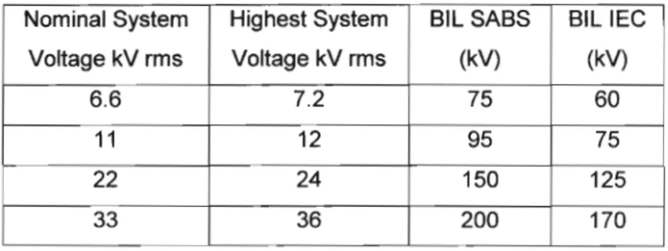
- Transformer and Surge arrester Bll Used in Eskom Distribution .2 Medium Voltage Transformer Bll
- MV Surge Arrester Bll
- Determination of a Gap with a Suitable Protective Margin
- Transformer Protection Using Surge Arresters .1 The Need for Transformer Protection
- Choice of Surge Arrester
- The reaction for the protection system to the Rod Gap .1 Dead Time in the 11 kV and 22 kV networks
- Earth fault created by Rod gap Sparkover
The higher the insulation level of the line, the greater the chance of damage to the connected equipment and line poles, Gaunt[14]. When a surge wave propagates across the network and becomes greater than the limiting voltage of the surge arresters. the resistance of the surge arrester temporarily becomes very low, allowing a limited current to be discharged to earth via an earth conductor and thus limiting the voltage on the transformer terminals.
IMPULSE SURGE ON TRANSFORMER WINDINGS
- Methods for Improving the Voltage Distribution in the Windings
- Characteristics of Normal Voltage on the Distribution Transformer The initial Voltage distribution of the transformer windings with the neutral point earthed
- The Nature of Oscillations Set Up In the Primary Winding
- The Mechanism of Transference of Surges to the Secondary Windings
- The solution for abruptly chopped wave
- The effects of Chopped Waves on the Transformer Windings The numerical solution for the chopped wave has been developed as follows
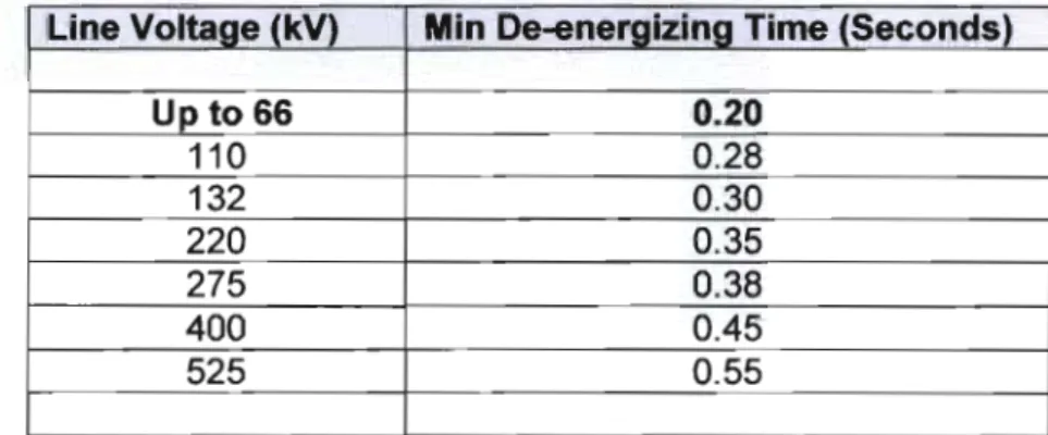
However, due to the transfer of overvoltage effects explained by Kelly [45], the influence of overvoltage must be considered. Eskom's pole-mounted distribution transformers are Delta-Star (DynN11) configurations with the secondary winding effectively earthed through the HV earth electrode. Initial voltage distribution of transformer windings with earthed neutral point. depends on the final and ground capacitance of the entire winding in Farads.
Cw = Capacitance from end to end in Farads Cg = Capacitance to ground of the entire winding. The impact of the impulse voltage is strongly influenced by the connection of the windings. This voltage component occurring at the secondary terminals therefore depends exclusively on the mutual capacitance (Cw) between both windings and their capacitances with respect to earth (Cg); it is therefore independent of the turns ratio.
These oscillations can be transmitted to the secondary winding by means of the built-up electrostatic and magnetic fields, so that the induced voltages depend on the distributed winding constants and the turns ratio of the transformer. An extensive background literature review of high-frequency transformer modeling is provided by Kelly [45].

Breakdown Mechanisms in Insulating Gases
Types of Gaseous Electric Fields That Are Considered
U EAve = -
Breakdown Criteria
Where nx is the number of electrons in an avalanche head at a distance x from the cathode no = initial number of electrons. Then a breakthrough occurs. For pd>(pd)min, the lower mean free path electrons make collisions more common. The energy gained between collisions is lower. The increased voltage required for breakdown to occur.
Factors Affecting Uniform Field Breakdown
Effective Area
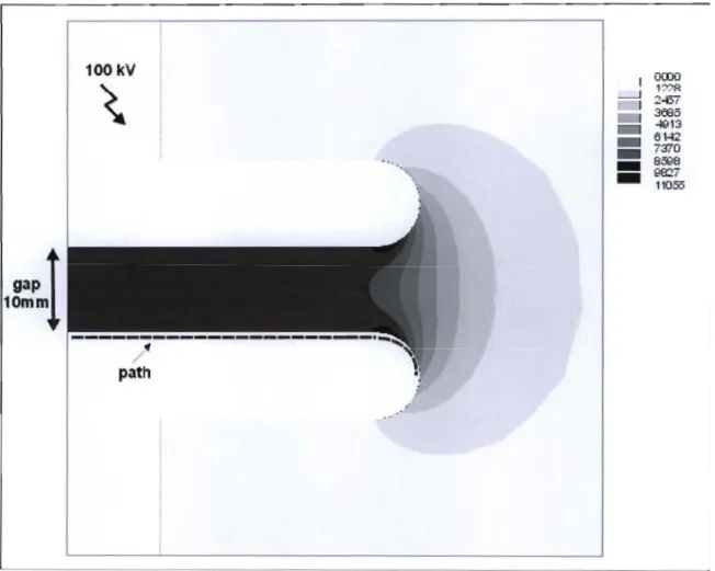
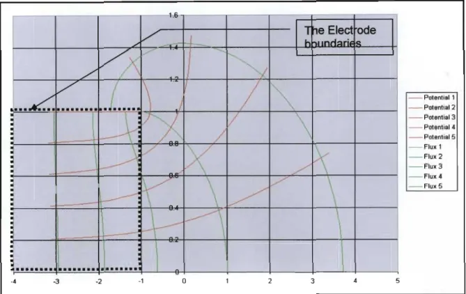
At this time, the electric field strength increases in accordance with the homogeneous field strength of the coplanar region. A two-dimensional axisymmetric finite element calculation of the electric field distribution is shown in Figure 5.9. In this case a slot spacing of 10 mm and an applied voltage of 100 kV), due to the crude illustration of the field strength in Figure 5.9, Naidu [26].
This is along the path on the surface of the electrodes which are shown in detail in Figure 5.9. An additional simulation result leads to the conclusion that the influence of the length of the gap in relation to the Effective Area is along the path on the surface of the electrodes are shown in detail in Fig. 5.9. For gaps above 10 cm in NTP, the breakdown voltage increases linearly with Pd up to the limits of Paschen's law.
In the case of sphere gaps, the breakdown voltages are independent of humidity and are also independent of the voltage waveform. A detailed review of the above theory shows that the following factors will influence the breakdown behavior of a spark gap.
MODELING AND SIMULATION RESULTS
- Femlab Modelling and Analysis
- Analysis of the FEMLAB Simulation studies
- Infinite Space
- Nearby Earth Plane Effects
- Determining Breakdown Voltage of the Rod - Rod Gaps
- Results of the FEMLAB Simulation for Breakdown Voltages
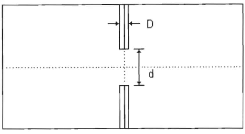
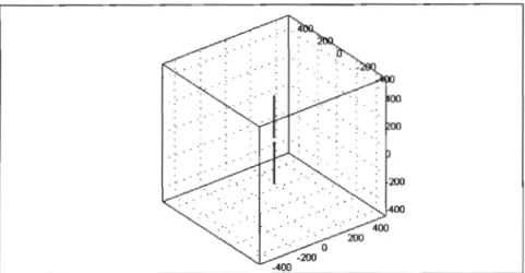
Each of the geometries was modeled using the electrical parameters detailed in Appendix B and these were solved using the Femlab linear solver. As expected, the electric field within the aperture was symmetrical about the center of the aperture. To determine the effects of grounded objects near the rod-rod openings, simulations were performed by placing a vertical ground plane parallel to the rods and holes, as shown in Figure 6.6.
Iterations are used to find the breakdown voltage by comparing the values at STD obtained from the simulation and normalizing using the a.,., curves shown in Appendix D. The code is detailed in Appendix 02. The accuracy of the calculation depends on the assumption that the electric fields across the rod - rod gaps were perfectly symmetrical. The data in Table 6.1 is a summary of the simulation values obtained by the FEMLAB software.
The data in Table 6.2 is a summary of the simulation values obtained by the FEMLAB software. The analysis of the results given in table 6.1 and 6.2 is dealt with in detail in chapter 7.
RESULTS AND DISCUSSIONS
- Laboratory Set Up
- Method Used To Apply the Impulse Voltage to the Gaps
- Test Specimens Used In the laboratory Tests
- The Results Expected for Gap Performance
- Analysis of the Simulation and Laboratory Results
- Analysis of the effects of an earth plane
- Approach for the Analysis
- Comparison of the laboratory and simulation Tests
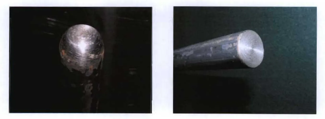
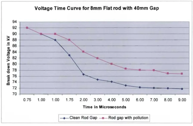
For the spark gap tests, a positive polarity voltage with waveform 1.2/50 I.ls pulse was used to flash the rod gap. No readings were recorded for the breakdown times; therefore, no analysis is available for the timing of the breakdown voltage. Therefore, two bars with diameter dimensions of D = 10 mm and D = 20 mm were selected for the experiments.
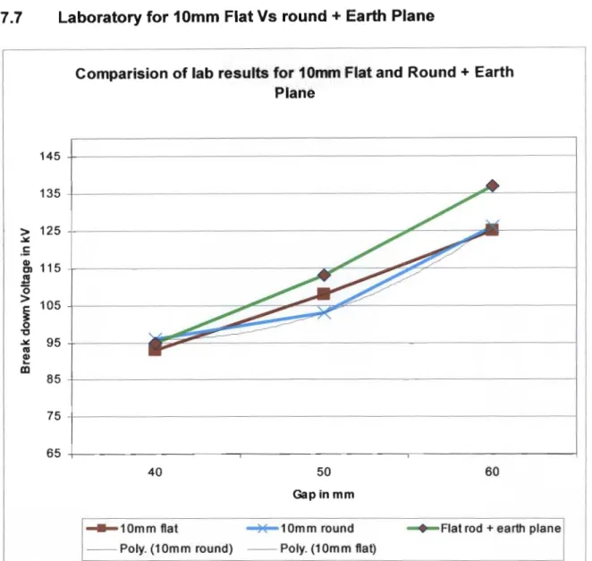
The results for two bars of size 10 mm and 20 mm diameter are compared with the aim of choosing a bar geometry (hemispherical or flat) and gap (40 mm, 50 mm, 60 mm) that will break down within the theoretical range of 96 kV to 120 kV offshore. - level conditions. A comparison of the simulated results against the laboratory results will be made for the two bar sizes 10 mm and 20 mm and the three gap sizes tested ie 40 mm, 50 mm and 60 mm. Each bar was tested under the influence of a ground plane for both 10mm and 20mm compared to each other for the three gap sizes tested ie 40mm, 50mm, 60mm.
The thesis was concluded by recommending the most appropriate bar diameter and gap size to suit the scope required. The average standard deviation of the battery for each result was calculated and varies between 1.5 and 4kV.
Comparing all rod diameters and Gaps for Flat and Round tip · Breakdown voltages
Gap Size [mm]
- Simulated results Vs Laboratory for 10mm round + EP
- Laboratory results 20mm Flat Vs Round Rod + Earth Plane
- Simulated Vs Laboratory for 20mm Round Rod + Earth Plane
- Laboratory results 10mm Vs 20mm Flat rod + Earth plane
- Laboratory results 10mm Vs 20mm Round rod + Earth plane
- Calibration values of Breakdown Results from Various Sources
- Concluding remarks
- CONCLUSION
Note, a curious result for the influence of the ground plane, i.e. the result has a higher breakdown voltage than expected. The simulated ground plane result is consistent with Kuffel [23], that is, the breakdown voltage of the gap with ground plane influences is lower. a) The 10mm flat bar is only suitable with a 40mm gap, even under the influence of the earth plane. The results show that the influence of the earth plane has not resulted in lower, but neutral breakdown values. a) The 20mm round bar is not suitable for 50mm and 60mm gap sizes and because the breakdown values are well outside the required range, these are excluded.
The laboratory and simulated values in Figure 7.8 above agree for 40 mm and 50 mm spacing, including the influence of the ground plane. The ground plane values are lower than the tests without ground plane influence. a) The 20mm bar with 40mm and 50mm spacing are both within the appropriate range and can be considered. Comparison of simulated results for 20mm round + ground plane .. 20mm round round simulated Round simulated+ground plane -Poly.
The laboratory and simulated values in Figure 7.9 above are consistent for the 40 mm gap, including the influence of the ground plane. The laboratory and simulated values in Figure 7.10 above for the 10mm and 20mm bars are similar in breakdown voltage for the 40mm and 50mm holes, including the influence of the ground plane.
The incident of lightning strikes to power lines", IEEE Transactions on Power Apparatus and Systems, New York. Insulation coordination of unshielded distribution lines from 1 kV to 36 kV", The High Voltage Co-ordinating Committee Task Force on the Lightning Protection of Distribution Lines, SAIEE. Practical insulation coordination of wooden pole distribution lines in lightning areas", IEEE Transactions on Power Apparatus and Systems, Swaziland, pp 503-508.
Metal Oxide Surge Arresters in AC Systems - Part 5: Protective Performance of Metal Oxide Surge Arresters", Electra No. 2003): "Voltage Drop Distributions Due to Power System Faults," IEEE Transactions on Power Apparatus and Systems, Vol Influence of Nearby of earth objects and voltage polarity on unidirectional decay of spherical gaps" lEE, Proc. NRS Guide for the use of slotless metal oxide surge arresters in distribution systems", NRS Rationalized user specification, South Africa.
Lightning-Induced Distribution Transformer Outage on a Florida Distribution System", IEEE Transactions on Power Delivery, Vol Performance Of Protective Rod Gaps For Medium Voltage Networks In The Presents Of Dust Particles Under Lightning Impulses", IEEE Transaction on Power Delivery, Vol14, pp. 1311 - 1316. SCSSCAAN Specification for Distribution Class Metal Oxide Surge Arresters Without Spark Gap", Eskom Distribution Specification The Location of Line Surge Arresters and Fuses on 11 and 22kV Lines to Protect Equipment Against Lightning", M.Eng Thesis, University of Stellenbosch, South Africa.
APPENDICES
APPENDIX B: THE SOFTWARE USED TO PERFORM SIMULATION B1 FEMLAB software used to model the electric field. In In-plane electrostatics, generalized application mode, we assume a symmetry where the electric potential varies only in the x and y directions and is constant in the z direction. In the axisymmetric electrostatics, generalized mode of application, we consider the situation where the fields and geometry are axisymmetric.
In this case, the electric potential is constant in the 'P direction, which means that the electric field is tangential to the r-z plane. When the solver is finished - go to post processing - this is the information we were looking for in the first place. Cross-sectional area parameters; slice; pre-determine quantities your way choose any of these; select the normal electric field.
Taken as a parallel L-C combination, let E be the voltage to ground impressed at the line terminal of the winding under consideration (due to the relatively high impedance of the transformer winding E will generally be approximately twice the surge voltage traveling), too. , let e be the voltage to ground at a point on the winding a distance x from the neutral end. From equation 4.4, the transmitted wave reaching the transformer will be either a double exponential wave (standard pulse type) or a damped sine wave and the slope of the wavefront decreases as shown in figure 4.3, Wedmore [40].
![Figure 2.5 Vertical test set-up for sphere Gaps, Kuffel [23]](https://thumb-ap.123doks.com/thumbv2/pubpdfnet/10631737.0/24.892.158.746.180.740/figure-vertical-test-set-for-sphere-gaps-kuffel.webp)
![Figure 2.6 Horizontal Spark Gap Schematic Diagram, Kuffel [23]](https://thumb-ap.123doks.com/thumbv2/pubpdfnet/10631737.0/25.892.173.757.161.546/figure-horizontal-spark-gap-schematic-diagram-kuffel-23.webp)
![Figure 2.8 Transformer, rod gap and surge arrester Breakdown Characteristic, Naidu [26]](https://thumb-ap.123doks.com/thumbv2/pubpdfnet/10631737.0/28.892.147.799.366.757/figure-transformer-rod-surge-arrester-breakdown-characteristic-naidu.webp)
![Figure 3.1 Over-Voltage Withstand Of the Transformer and Surge Arrester, Schneider [37]](https://thumb-ap.123doks.com/thumbv2/pubpdfnet/10631737.0/41.892.143.791.642.916/figure-voltage-withstand-transformer-surge-arrester-schneider-37.webp)
![Figure 3.3 Behavior of surge arrester to Over-voltage conditions. Schneider [37]](https://thumb-ap.123doks.com/thumbv2/pubpdfnet/10631737.0/43.892.161.756.119.410/figure-behavior-surge-arrester-voltage-conditions-schneider-37.webp)