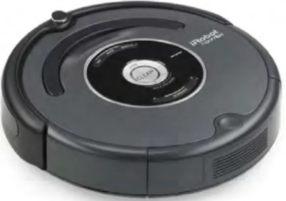
This robot is built from the ground up using parts obtained from various places. The Mechatronics group from the Mechatronics and Micro Manufacturing (MMM) competency area at CSIR is involved in the development of various autonomous mobile robots.
Background information and research objectives
This chapter presents the outline of the project and provides background information, followed by the motivation for the study. Along the way, this study also discusses obstacles and design steps for the development of the vehicle.
Problem statement
One of the goals of this research study was to try to find low-cost solutions for the mechanical design, electronics, sensors, and software required to build a courier robot. This vehicle is part of this initiative and will contribute to the Group's operations.
System specifications
Maneuvering: The vehicle must be able to maneuver indoors and turn on the spot. Vehicle Position Accuracy: The vehicle shall be able to determine its position indoors and outdoors with similar x and y errors of ± 1 m and orientation errors of less than 10°.
Definitions, assumptions, limitations and delineations
Thesis outline and chapter overviews
- Literature review
- Mechanical design
- Sensors
- Electronic design
- Software design
- Control system design and experimentation
- Validation and conclusions
In this chapter, the outcomes of the development of the system are validated, followed by a conclusion about the study. In addition, some recommendations are made regarding further development of and experimentation on the Meercat project.
Background
Mobile robotics history
The research field of mobile robotics is vast to say the least, so it's a challenge not to get lost in the literature. A multi-angle camera system on this robot was used to measure the distance to obstacles in the robot's path.
Service robot applications
It is also clear that service robots will enter our homes in the near future. As discussed in [27], the implementation of these systems is of obvious benefit, but it requires thorough planning and proper integration with the rest of the logistics system.
Classifications and terminology
In official terminology, this is known as the study of human-robot interactions (HRI), a new field of study. In their research on robot interfaces, Bartneck and Okada make a first attempt to understand and classify the subject [29].
Locomotion
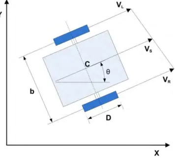
The robot uses a motor on each wheel; this arrangement is known as a differential drive system. When the robot's center of mass is above the wheel axles, one or more steering wheels are usually added for stability.
Perception
- Odometry
- Magnetic sensors
- Inertial sensing
- Range finder sensors
Although a magnetic sensor seems ideal for measuring vehicle attitude, a major performance disadvantage of these magnetic sensors is that they are sensitive to other disturbances in the Earth's magnetic field. Industrial ultrasonic sensors compensate for these effects, but the sensors used in many robotic platforms do not.
Localisation
Global navigation satellite systems
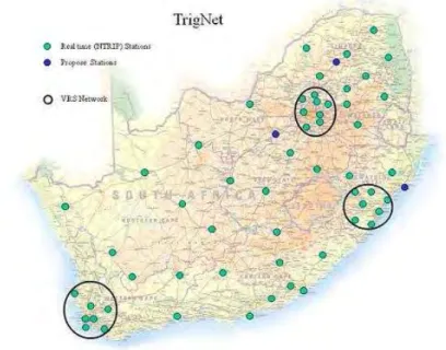
For outdoor use, GPS is a satellite technology created by US military developers to aid in accurate position acquisition by the Navy, Army, and Air Force [61, 62]. Such stations are widely available in the US, but until recently such service did not exist in the interior of South Africa.
Cognition
Autonomy levels
Examples of these systems can be found in devices sold by companies such as JBT-Corporation [72], Transbotics [73] and Egemin [74]. This can be in structured or unstructured environments, a highly specialized example being the MicroMouse competition [75].
Planning and navigation algorithms
- Road mapping
- Cell decomposition
- Potential field algorithm
- Obstacle avoidance
The last method is the potential field algorithm, where the concept of attractive and repulsive fields is used. During planning, we direct the robot away from objects, as they have repulsive fields, and an attractive field directs it towards the target.

Software frameworks
The common denominator of all these frameworks is the fact that RDE emphasizes code reuse. A new development worth noting is the recent development of an open source Robotic Operating System (ROS) [93] being developed at Willow Garage [94].
Summary
The ROS development effort is a continuation of efforts at the Artificial Intelligence Laboratory at Stanford, where the Stanford AI Robot (STAIR) was developed [95]. For example, while the sensor may not report any obstacles in its measurement field, this may be as a result of tilting the platform and not as a result of the absence of obstacles.
Mechanical design parameters
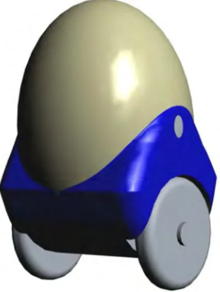
One problem is that the platform is constantly moving in an attempt to balance itself. This effort has a power cost; battery power is constantly consumed during balancing, and when the batteries run out, the platform overturns.
Concept drawings
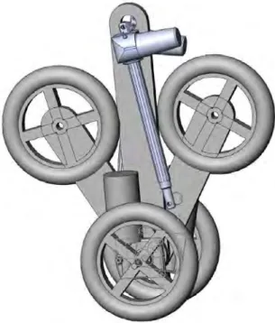
A transparent top will house some of the sensors and a warning beacon, protected by the casing. Concept drawing 3, shown in Figure 3.3, shows a concept of an adaptable multi-wheel mechanism, where the wheels can be used for stabilization of the platform in certain operational modes, but also for self-correction or even angle of the sensors.
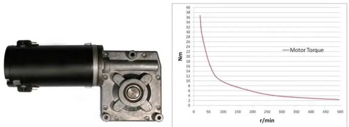
Mechanical component selection
An advantage of this sourcing method is that the project benefited from the supplier's higher purchasing quantities. From a mechanical design point of view, the design is not optimal because the available power of the engines, as shown in Figure 3.4, is greater than what is required for the vehicle.
Vehicle iterations
Summary
This chapter discusses the selection and operation of the sensors used on the Meercat platform. These sensors are discussed in the following sections of this chapter, followed by individual conclusions about the use of these sensors.
Motion sensors
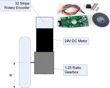
Wheel encoders
In Figure 4.2, the CHA and CHB signals are the typical signals generated from a standard quadrature encoder where the phase difference between CHA and CHB indicates the direction of rotation, and the DIR and CLK signals are generated by a decoding process which uses CHA and CHB as input signals. The CLK signal indicates a change in the state of the encoder and the DIR signal indicates which direction the wheel is turning.
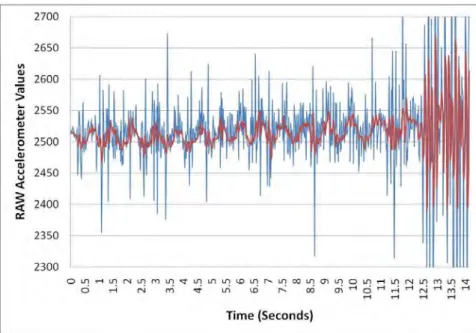
Accelerometers
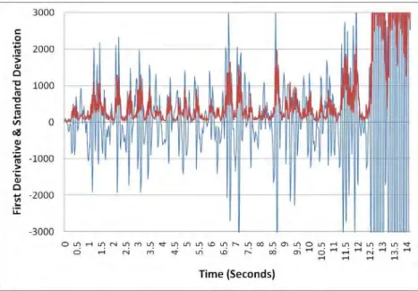
After the slope of the data was calculated using the first derivation algorithm, the standard deviation of that data was calculated. Applying the lowest threshold to the standard deviation data then provided a numerical method for determining whether the system was at rest.
Gyroscopes
Obstacle sensors
- Bumper sensors
- Ultrasonic range sensors
- Infrared beam sensor
- Laser beam sensor
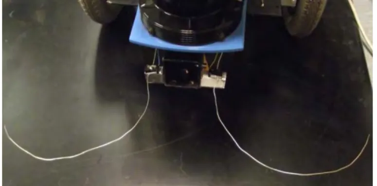
On the Meercat, as shown in Figure 4.8, two bumper sensors are implemented, which are activated by whiskers emerging from the vehicle and covering the close area in front of the vehicle. However, the performance of the sensor was interesting enough to be used in the application for some experiments, as the cost of these types of devices is also expected to decrease in the near future.
World position sensors
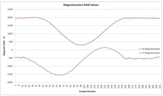
Compass
The raw data obtained from the calibration process is shown in Figure 4.14, where the vehicle was slowly rotated around its axis and the data was sampled at an interval of 5 Hz. The data is displayed as radians ranging from -π to +π, as this is the platform orientation standard used in the higher levels of the software.
GPS
The Z-axis data only plays a role when the vehicle needs to be tilted and this is not the case in an indoor environment where the tests were conducted. However, based on the tests carried out, this seemed a bit optimistic as reception of satellite signals in the office corridor was never successful.
Differential GPS
The manufacturer claims that the SuperSense feature enables indoor GPS as the module can receive signals up to -161 dBm. The crux of any augmentation service is that it must be physically close to the point of interest, as the atmospheric corrections are only relevant within a limited range.
Summary
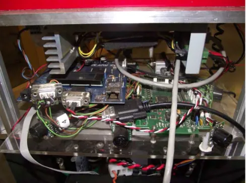
Almost all the electronics are mounted in a single bay on one level of the Meercat platform and are easily accessible. Electrical diagrams and data sheets for the individual products can be found in the data package.
I/O board: Generic CPU
EVK1100 AVR32 UC3A evaluation board
The interesting fact is that this processor is sold at a lower cost than the 8-bit processor on the Generic CPU Board. The processor is set to run at its maximum speed of 66 MHz, and most of the I/O capability on the EVK1100 board is used.
Embedded personal computer
The choice to work on the front end did cause problems during the development phase. The downside of this solution is a limited amount of space compared to other drive solutions.
Radio remote control interface
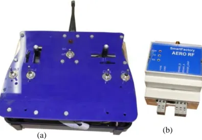
The platform is shown in Figure 5.4 in a rugged industrial enclosure and its form factor is suitable for positioning it in Meercat's electronics bay. The receiver module is a standard RF Smartfactory module powered by 24 V and is shown in Figure 5.5 on the right side.
MotorController: AX2550
The combination of the gearbox and the electronic brake operated by the controller is enough to keep the vehicle in place even on steep slopes. In the case of Meercat, the controller powers the motors using a 24V supply and runs on the same 24V supply.
Human feedback
Another advantage of choosing this car controller is the fact that it implements regenerative operation, charging the batteries when the vehicle slows down. No other braking system is implemented on the robot as the electronic braking solution is sufficient for both dynamic situations as well as static situations.
Power system
In addition, the regenerative nature of the motor drive should also increase the range of the system.
Summary
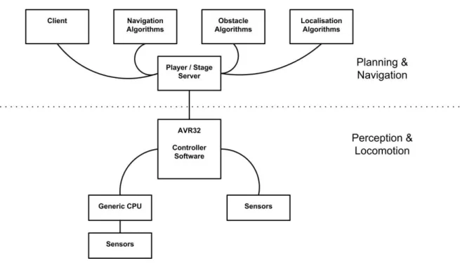
At the lowest level is the software contained in some sensors and the sensor interface software on the general CPU board. This application forms the core of the entire Meercat system, because it determines whether and how the robot perceives and moves.
Generic CPU software
Any CRC errors found in the master message cause the slave to ignore the polling message. Similarly, any CRC errors in the slave message cause the master to ignore the reported data.
AVR32 software
FreeRTOS and software framework
For more complex software projects, using an operating system can be a big help. The FreeRTOS real-time operating system [113] was ported to the AVR32 processor by ATMEL engineers and is available for free.
Control task
When a project is started, the developer can easily make choices about which drivers are needed and they are automatically added to the project. However, this becomes less of an issue as the processor has enough speed to handle software structures that may not be completely optimal.
MODBUS RTU protocol task
While all of these features are convenient, the initial impression is one of an overwhelming overhead on the project. In this way development can happen quickly, new data/variables can be easily added to the table and the host only needs to ask for the extra available registry spaces.
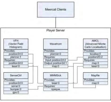
Player software
The first driver, called SenseCtrl, was developed to provide an interface to the Meercat hardware. The SenseCtrl driver developed as an interface to Meercat's sensors and actuators implements the MODBUS protocol to communicate with the AVR32 processor.
Development and debugging
Communication protocol testers
To test and verify the MODBUS protocol between the AVR32 processor and the built-in PC, another program was written to verify the functionality of the protocol commands and checksum routines. A screenshot of the MODBUS protocol test program is shown on the right side of Figure 6.5.
Mapping application
Once the communication protocol was tested and found reliable, the key communication routines developed under Windows were transferred and reused in the development of the Meercat platform manager under Linux. The surveys shown in some of the experiments in Chapter 7 were created from the recorded data of those experiments visualized by the Map Builder program.
Summary
This situation is acceptable in the experimental phase, but if the platform is put into actual daily use, this factor must be addressed. The most simple solution to this problem would be to report back to a human operator that the platform is completely stuck and needs assistance.
Meercat control modes
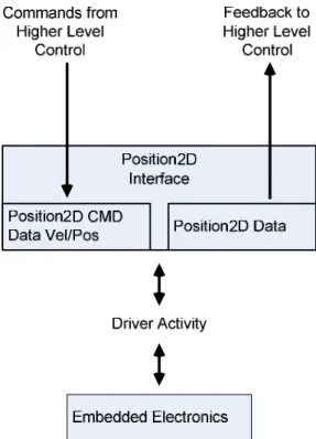
The behavior of the driver and the embedded controller in speed control mode is shown in Figure 7.2. The driver inspects the state of the onboard controller so it knows when new position commands can be passed.
Odometry calibration
The circumference of the wheels was measured by wrapping a cord around the wheels, thus giving a good initial approximation of the actual diameter of the wheel. These values are stored in the configuration file which is transmitted to the controller at system startup.
Localisation and navigation experiments
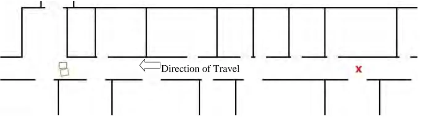
- Wall-following experiments
- First odometry test
- Compass testing
- Gyroscope testing
- Odometry and GPS test
- Advanced Monte Carlo localisation experiment
- Navigation experiment
- Differential GPS navigation experiment
Note that the "spiking" in the compass data is an artifact of the representation, where the heading goes from positive π to negative π. The results of these tests are shown in Figure 7.9, where the motors are switched on and off intermittently, as can be seen in the reading jump.
Summary
This chapter discusses the validation of the research study covering all the research objectives on a section by section basis. Discussions throughout the previous chapters and the results of the described experiments will help in the evaluation of the performance of the Meercat courier robot.
Validation of robot construction
- Mechanical components
- Sensors
- Electronics
- Power and drive
- Computing and communication
The implementation of this localization solution had a positive effect on the success of the platform. A possible minor optimization of the Meercat mobile robot system would be to incorporate a monitoring system into the 12V power rail.
Validation of localisation
Indoor localisation
Outdoor localisation
Validation of navigation
Using the predefined map of the terrain, combined with the use of a wavefront planning algorithm, as shown in section 7.3.7, the Meercat robot was able to plan a path to the intended targets. Unexpected stationary and moving (human) obstacles were detected and avoidance of these obstacles was achieved through the use of the player project's VFH driver.
Validation of specifications
For shorter navigation lengths the odometry, gyroscope and even compass sensors can be used, while during longer indoor movements the location is accurately tracked through the use of the AMCL algorithm. Outdoor localization using the differential GPS solution worked well and it has been shown that the location of the mobile robot can be tracked very accurately.
Conclusions
Speed tests of the vehicle showed a potential speed far in excess of human walking speed, so much so that the speed of the mobile robot was limited in software as the maximum speed was deemed too high in light of the available sensor data. However, the boundary is not a static implementation, such as a percentage limit on motor output, but a dynamically monitored maximum platform speed.
Summary of contributions
Although all of the navigation experiments resulted in successful operation of the robot, all of these experiments were conducted under supervised circumstances, and more work needs to be done to ensure that Meercat is a truly autonomous robot. The first steps towards such a solution could be the creation of one or more docking stations for charging purposes, an operator interface (receptionist) to easily command the robot, and the availability of a situational status display interface with alarm functions when they arise. situations that the robot cannot handle.
Recommendations
34;Improved Mecanum Wheel Design for Omni-directional robots," i Proceedings of the Australasian Conference on Robotics and Automation, Auckland, New Zealand, 2002, s. Feng, "Gyrodometry: A New Method for Combining Gyros and Odometry in Mobile Robots, " i Proceedings of the 1996 IEEE International Conference on Robotics and Automation, Mineapolis, USA, 1996, s.
![Figure 2.1: Robot infrastructure [32]](https://thumb-ap.123doks.com/thumbv2/pubpdfnet/10638322.0/23.892.232.705.393.817/figure-2-1-robot-infrastructure-32.webp)