저작자표시
-비영리
-변경금지
2.0대한민국 이용자는 아래의 조건을 따르는 경우에 한하여 자유롭게
l
이 저작물을 복제
,배포
,전송
,전시
,공연 및 방송할 수 있습니다
.다음과 같은 조건을 따라야 합니다
:l
귀하는
,이 저작물의 재이용이나 배포의 경우
,이 저작물에 적용된 이용허락조건 을 명확하게 나타내어야 합니다
.l
저작권자로부터 별도의 허가를 받으면 이러한 조건들은 적용되지 않습니다
.저작권법에 따른 이용자의 권리는 위의 내용에 의하여 영향을 받지 않습니다
.이것은 이용허락규약
(Legal Code)을 이해하기 쉽게 요약한 것입니다
.Disclaimer
저작자표시
.귀하는 원저작자를 표시하여야 합니다
.비영리
.귀하는 이 저작물을 영리 목적으로 이용할 수 없습니다
.변경금지
.귀하는 이 저작물을 개작
,변형 또는 가공할 수 없습니다
.Master's Thesis
AngGo-N: Transformable Personal Mobility Providing The Autonomous and Manual Driving Mode
Donghun Kang
Department of Creative Design Engineering, UNIST
Graduate School of Creative Design Engineering
2021
AngGo-N: Transformable Personal Mobility Providing The Autonomous and Manual Driving Mode
Donghun Kang
Department of Creative Design Engineering, UNIST
Executive Summary
This thesis describes the development of a Shared Indoor Smart Mobility device called AngGo-N. During the development process, We conducted researches and studies on PMVs(Personal Mobility Vehicles) and AngGo. AngGo is the indoor personal mobility finding potential users who need indoor transportation movements. The goal was to develop Shared Indoor Smart Mobility and to ensure AngGo-N meet user requirements practically. This study contributes to how a Shared Indoor Smart Mobility can meet transport users' needs around an indoor environment. We state two research questions to develop AngGo-N. The first one is 'How to improve the acceptance of the SISM?'. The second one is 'What is the needed design implication of SISM?'. Based on AngGo's problems, We found solutions to them and apply them to AngGo-N's design. We applied transformable factors in AngGo-N to give interaction between user and personal mobility. The AngGo-N give user different forms in autonomous mode and user-controlled manual mode. After making the prototype of AngGo-N, We do competitive testing and value opportunity analysis. With the result of the analysis, We make answers for those two research questions.
Keywords: Transformable Personal Mobility Vehicle, The Indoor Mobility, Shared Indoor Smart Mobility, SISM, AngGo, AngGo-N
Table of Contents
Introduction ... 2
Background... 2
Related Works... 4
Developing a New Type of Micro-mobility ... 6
Research Aim and Scope ... 7
Thesis Structure ... 8
Preliminary Study ... 10
The AngGo ... 11
Conclusion of the preliminary study ...12
Problems of the AngGo... 14
Usability Test ...15
Interaction Test ... 17
Focus Group Interview: AngGo Developers... 20
Mechanical Review ...22
Summary and Findings ... 24
AngGo-N ... 26
Design Features ... 26
Three types of operating mode ... 29
Mechanical Structure ... 39
Prototype Development Procedure ... 47
Supplements and Findings During Development ... 55
AngGo & AngGo-N ... 58
Main Research Questions... 58
Expected Contribution ... 60
Discussion ... 62
A detailed discussion about answers of value opportunity analysis ... 62
Further Work and Limitation ... 65
Conclusion ... 67
References 61
Appendices 65
Tables
Table 1. AngGo Specifications[38] ... 11
Table 2. AngGo-N manual mode example equation ... 34
Table 3. Requirements of personal mobility ... 56
Figures
Figure 1. Future states of mobility[4] ... 4Figure 2. Experiment procedure [9] ... 7
Figure 3. Research Aim and Scope ... 7
Figure 4. Model of AngGo platform[36] ... 10
Figure 5. Setup of the obstacle evasion ... 14
Figure 6. Test layout[9] ... 14
Figure 7. AngGo mobility useability test survey results[38] ... 15
Figure 8. Rider posture when in use[38] ... 16
Figure 9. Visual feedback using LED strips inserted right below the seat ... 17
Figure 10. Map of the test environment and the initial location of AngGo and subject ... 18
Figure 11. Test environment ... 18
Figure 12. Box plot for reaction time, bimodal (visual&auditory), o = outliers ... 19
Figure 13. Interview with AngGo Developers ... 20
Figure 14. The first and second prototype (left: second prototype, right: first prototype) ... 22
Figure 15. The speed induced in each wheel during rotation ... 23
Figure 16. Features and Characteristics of the lounge chair and SISM ... 26
Figure 17. Design Mood board of AngGo-N ... 27
Figure 18. Concept Modeling of AngGo-N ... 28
Figure 19. User Posture in use (User model height was 170cm) ... 28
Figure 20. ToF description of AngGo-N ... 29
Figure 21. AngGo-N mode scenarios ... 30
Figure 22. control method description ... 32
Figure 23. Distance sensor description ... 32
Figure 24. AngGo-N movement based upon the given equations ... 35
Figure 25. AngGo-N system diagram ... 36
Figure 26. User scenario of using AngGo-N in the indoor building ... 37
Figure 27. AngGo-N block diagram ... 37
Figure 28. Implementation of electric components of AngGo-N in real size of foams ... 38
Figure 29. Implementation of electric components of AngGo-N ... 38
Figure 30. AngGo-N first mechanical concept model ... 39
Figure 31. Force gauge measurement ... 41
Figure 32. Equation definition description 1 ... 43
Figure 33. Equation definition description 2 ... 43
Figure 34. Structural change by sitting, front view ... 44
Figure 35. Structural change by sitting, side view ... 44
Figure 36. Gear Information [40] ... 45
Figure 37. AngGo-N Gear Information Detail [40] ... 45
Figure 38. User test in real size model prototype ... 47
Figure 39. the initial stage of the frame ... 48
Figure 40. Reinforced wheel fork of AngGo-N ... 48
Figure 41. First form iteration process of AngGo-N... 49
Figure 42. Exploded image of AngGo-N ... 50
Figure 43. Assembled image of AngGo-N ... 50
Figure 44. Fabricating process of Exterior plates ... 51
Figure 45. Parts assemble process ... 51
Figure 46. Seat Parts assemble process... 52
Figure 47. A finished prototype of AngGo-N(Autonomous mode) ... 53
Figure 48. AngGo-N finished prototype (Standby and Journey Mode) ... 54
Figure 49. Value opportunity analysis meaning [26] ... 59
Figure 50. value opportunity analysis for SISMs answer mean value and criteria ... 60
Figure 51. value opportunities score criteria mean scores ... 62
Figure 52. Re-align value opportunity analysis score of two platforms ... 62
Explanation of Terms and Abbreviations
Terms and Abbreviations Explanation
Personal Mobility
Personal mobility is divided mainly into PMD(Personal Mobility Device) and PMV(Personal Mobility Vehicle). It has the characteristic of using electricity as the primary power source.
Personal Mobility Vehicle (PMV)
Vehicles subject to the domestic automobile management law among personal mobile devices. Personal Mobility Vehicle is composed of a shape equipped with lighting devices, braking devices, steering devices, and riding devices while maintaining a car or two-wheeled vehicle's chassis and body.
Personal Mobility Device (PMD)
Among personal mobility devices, products subject to the Electrical Appliances and Household Goods Safety Management Act. Personal mobility Device has a relatively simple structure and lightweight. There are Segway and Electric Kickboard that sold worldwide.
AngGo The Shared Indoor smart mobility platform that developed
in the UNIST DECS lab. In 2020-12-15, the third version of the product was coming out[36].
AngGo-N The transformable type of Shared Indoor Smart Mobility
platform introduced and developed in this paper.
Smart Mobility The mobility forms of transport that can transfer users to their destination.
Micro-mobility
Mobility constitutes forms of transp006Frt that can occupy space alongside bicycles. Multiple criteria can be applied to define micro-mobility[8]. Weight is less than 500kg, passenger or payload capacity, powertrain(human-powered or electric), maximum speeds or ranges, and others[41].
SISM Shared Indoor Smart Mobility.
SIOSM Shared Indoor & Outdoor Smart Mobility.
Value Opportunity Analysis (VOA)
Value opportunity analysis maps the extent to which a product's aspirational qualities align with people's
idealized lifestyle or a fantasy version of themselves[25]. A technique can be used to identify the aspirational attributes of a product or service.[26]
Competitive Testing
Competitive testing is the process of researching to evaluate the useability and learnability of our competitors' products[25]. Competitive testing provides design teams with an opportunity to assess competitors' products from the end user's perspective [39]. According to studies, the difference between our site and our competitors' can reveal a 68% gap in useability[42].
1
Introduction
Background
Related Works
Developing a New Type of Micro-mobility
Research Aim and Method
Thesis Structure
Introduction
Background
Recent innovations, such as electric scooters, shared bikes with and without docks, and personal mobility devices, reduce personal vehicles' need to transport people at short distances. Micro- mobility means short distance transport using a personal mobility device such as kickboards, Segway, and mini electric scooters. Users have welcomed the rapid introduction of these devices in recent years. Micro-mobility services have also drawn positive responses from users. The introduction of appropriate size devices for a particular space enables better utilization of these spaces, reducing greenhouse gas emissions [1]. More than half of the world's population currently resides in urban areas. This ratio is expected to increase by two-thirds by 2050 [2]. Therefore, in all modes of transport, the demand for mobility of urban passengers will double from 2015 to 2050, all of whom will need proper transportation methods [3]. Similar requirements exist for indoor environments, despite several types of micro-mobility devices for outdoor use. Walking in vast spaces such as military bases, airports, shopping malls, conference centers, or fairgrounds can be exhausting for some people. It can detract from their enjoyment of the exhibits or the full achievement of their visits' particular purpose.
Previously, Smart Mobility refers to products that use a motor, gyro-sensor, and acceleration sensors. However, now it is hard to find the difference between Smart Mobility and personal mobility because of technologies. Thus, smart mobility includes electric bicycles and electric scooters from a general point of view. As products that are not smart begin to be included, the term Personal Mobility Vehicle is also being used. This means that a new mobility type has come out. At the same time, the form and functions should be developed for new Personal Mobility Vehicles.
This thesis proposes a shared indoor smart mobility (SISM) device, an autonomous platform with a seat that allows users to sit when they move in an internal environment. The indoor mobility devices' design shall consider the operation modes, appearance, and interaction systems comforting a given indoor environment. We applied sensors to set up a system that allows the
SISM device to navigate an indoor environment without colliding with obstacles indoors while recognizing potential users as they approach.
Related Works
Future states of mobility
Several technological and social progress is radically changing the way people are transported, affecting many industries. With this trend, four types of mobility have emerged within the new mobility ecosystem have emerged. This occurs at the intersection of the person who owns and drives the vehicle (Figure 1)[36].
Figure 1. Future states of mobility[4]
Privately owned mobility
This, called private property mobility, will still be a gold standard as consumers choose flexibility, privacy, convenience, and safety. As they like to drive alone, even though it is its advanced technology, it is assumed that the driver's auxiliary power source will not be replaced.
Shared mobility
It is expected that co-mobility will continue to increase through the use of shared vehicles or car sharing. Motivated by expanded markets and competition, car-sharing services will be increasingly promoted as part of the novel and specialized customer segments. Shared mobility will account for a significant portion of regional transport needs. The number of households with more than one vehicle will be reduced. Likewise, many people are likely to stop owning mobility.
Privately owned driverless mobility
Drivers will choose more and more for safety and comfort reasons. However, autonomous driving technology for safe and economical means for general mobility is still at level 2 [21].
People still expect highly customized vehicle expansion within the country market to meet homes or individuals' specific needs.
Shared driverless mobility
Autonomous driving and car-sharing are expected to converge in the form of driverless shared mobility. Mobility management firms and fleet operators provide extensive customer experience to meet this need from different perspectives. In the future, it will provide mobility in the form of a faster, safer, cleaner, and more convenient overall system.
Developing a New Type of Micro-mobility
Micro-mobility is essential so that in areas where a high proportion of the population depends on public transport and at the same time, adaptive transport is readily available. The population that relies on public transport includes people with physical disabilities or lacking a driver's license [5].
These groups require micro-mobility to access public transport. Micro-mobility solutions can also provide short trips within confined spaces, such as universities, corporate campuses, and military bases. It is worth noting that public transport consists mainly of short-distance mobility. For example, the average distances people travel by bus, train, and tram are 3km, 6km, and 8km, respectively. Thus, some of these modes of transport can potentially be replaced by micro-mobility solutions. Oliver Bruce, an investor that also propagates micro-mobility, estimates that more than 2.2 trillion km of U.S. passengers' annual travel and more than 6.4 trillion km of worldwide annual travel could be replaced micro-mobility devices[8]. Thus, micro-mobility is targeting a market worth potentially hundreds of billions of dollars and deserves serious consideration [6]. Any city can introduce micro-mobility into a new test case in the management system.
This initiative can be sponsored by a digital platform integrated into a single group to accommodate all available vehicles to supply and demand optimization and create the highest global efficiency across systems [7]. However, some industry leaders have pointed out that others are ostensibly discussing possible vehicle performance, shape, and size. These leaders have also predicted the emergence of new and multi-faceted designs that will expand the definition of what we consider micro-mobility [8].
Before developing a new type of personal mobility, we search for previous work for indoor mobility development. An in-depth analysis was conducted in another thesis to understand why the most popular Xiaomi Segway, scooter, and kickboard models cannot be used for indoor mobility[9]. In an experiment that consisted of 24 healthy men and women between the ages of 20 and 30, he asked subjects to ride on their respective test mobility devices in the building for 10 minutes. The indoor test rides were conducted with three currently available outdoor mobility devices (Figure 2)[9].
Research Aim and Scope
This is the main research question about developing the Shared Indoor Smart Mobility platform based on useability, interaction, and design development process. To answer two research questions, we conducted competitive Testing with AngGo and a new type of mobility.
Figure 2. Experiment procedure [9]
Thesis Structure
In Chapter One, we set the aims and scope of this research based on our research motivation.
We investigate the research methodology's practical basis—Research through Design and prove—and describe our approach as research through prototyping from the lab. In Chapter Two, we emphasize the whole process of how we make the AngGo platform within the SISM concept. Physical appearance is explained based on design research and the expected appearance of the AngGo. Overall systems of the AngGo are expressed based on sensor selection, system details, system implementation for semi-autonomous mode, and system implementation for manual mode. Chapter Three proceeded with the useability test, interaction test, developers' interview, and structure review with SISM AngGo. Usability test in manual mode. The interaction test was about interaction experiments in autonomous mode. AngGo developer interview was about design implementation in the indoor and outdoor environment.
The structure review was also done to see a detailed design. Based on this research, we listed all findings. Moreover, we arranged and put together results in interim results in Chapter Four. In Chapter Four, we introduced developed SISM mobility AngGo-N based on insights in previous researches. Overall systems of the AngGo-N are introduced. The prototype development procedure is listed, with the implementation process. We run competitive testing with AngGo and AngGo-N within the same environment. Research questions, participants, experiment description, results were listed in chapter Five. Next, we discussed experiment results, which are run in Chapter Six. Limitations of this thesis are listed in it.
Finally, we concluded our master thesis about Shared Indoor Smart Mobility development.
Moreover, further works topic came out in here Chapter Seven.
2
Preliminary Study
SISM development
Physical Appearance of the AngGo
Expected product performance of the AngGo
Conclusion of Preliminary Study
Preliminary Study
Subsequently, we administered interviews and questionnaires based on their experiences with the mobility devices they tested [9]. Following the indoor test drives' survey results, we created a diagram, shown in Fig. 3, that depicts user experiences. The seated e-Scooter received the highest overall score. In contrast, the Segway, which is operated by leaning the users' body, scored low on the "universally accessible" test parameter because it was difficult to manipulate. Subjects were asked to name the essential factor to consider when designing a shared indoor mobility device.
The 24 responses were classified into four value categories: 13 subjects declared convenience, 9 chose safety, chose to trust, and chose aesthetics. Based on these results and further analysis of the interview results and keyword extraction results, we determined that relief, notice, and amusement were the three essential components for our SISM system. The SISM device was designed to consider the subjects' opinions, which were classified according to four parameters: accurate and safe control, rider comfort, trunk storage, and amuse hands-free operation. To allow a more intuitive operation mode for SISM users, the system was designed to be controlled with both feet.
We developed a foot-controlled SISM mode of operation, which is represented by corresponding sketches and models. The conceptual design defined the structure for pushing and pulling the pedal plate. The pedal plate was designed to accommodate the user's feet up to 300 mm in size.
The surveyed users' posture determined the device's actual size and riding posture. For the useability test of the pedal plate, we built a platform called AngGo, as a prototype of the SISM device proposed in this thesis (Figure 4) [36], [37], [38].
Figure 4. Model of AngGo platform[36]
The AngGo
The primary function of a seat for users to sit. The seat's endpoint was taken to match its appearance with the structure containing the rear side's curvature. To keep the user's hand free during operation, a pedal plate was added. The saddle and trunk were designed by applying flat elements (e.g., the pedal plate) to the platform's body. An intuitive parallelogram-shaped lateral body impression was added by introducing curvature. By giving the design a larger curvature at the rear part of the side body, the design has a forward lean direction. The SISM main body aligns with the side body lean. The side body's top line was designed to be higher than the saddle so that the users could safely sit and hold on if necessary.
The pedal plate was designed to have a slight incline to make it easier to push and pull it when in use. The curvature of the pedal plate was also designed to provide clues to directionality. This was achieved by designing the front with a larger curvature, thus giving clues about the direction of movement (Figure 4).
Table 1. AngGo Specifications[38]
Dimensions (L x W x H) 120 cm x 80 cm x 60 cm
Weight 20 kg
Maximum load 100 kg
Maximum speed 8.0 km/h
Operation time per charge 5 hours
Power supply 36 V, 10 Ah
Expected product performance of the AngGo
The AngGo Platform has a maximum 120mm x 800mm x 600mm width to provide enough space to sit comfortably. The maximum load was set at 100 kg as it is designed to accommodate a single user.The maximum speed was set to 8 km/h, similar to the average person's fast walking speed. Its primary function is indoor mobility. The AngGo also has the function of avoiding collisions with people walking in the same space. The AngGo was designed with a total weight of less than 20 kg. The battery capacity was set accordingly, aiming for a runtime of 300 minutes per charge (Table 1).
Conclusion of the preliminary study
AngGo interacts with users by making light and sound interaction on the seat side. However, these kinds of interactions make limitations in the noisy or lighting indoor environment. To overcome these limitations, we apply transformable interaction to personal mobility. The definition of transformable design has three conditions. The transformable design can transform from one state with unique functionality and physical form to another state with another functionality and physical form. These individual states can exist in two or more states. The product variations should be intended in the design process. Deformation must be reversible, and the product is not separated after transformation. More advanced technology and a high difficulty design process are required to design and apply the transformable structure in personal mobility. However, through this, it is thought that it will be possible to save space and time resources that the product continuously occupies and improve useability and functionality. With the development of technology, foldable display smartphones that were not previously commercialized appear on the market. The improvement in useability due to the change in functionality made through the transformable is well received. [35]
3
Problems of the AngGo
Tests and Evaluation of AngGo
Usability Test
Interaction Test
Focus Group Interview: AngGo Developers
Mechanical Review
Summary and Findings
Problems of the AngGo
Field experiments were conducted to test the AngGo prototype and determine how efficiently this SISM platform can be implemented. The experiment was carried out in the first-floor lobby of a UNIST building, measuring 3000cm x 12000cm (Figure 6). Pedestrians getting through the building were not prevented during the test. The field experiment took about an hour, and fourteen people went through the entire process of interacting with the AngGo. Evaluate the design elements of overall useability and mobility while measuring footplate manipulation's intuition and learning ability. Simultaneously, we tried to extract design elements deeply related to our ability to learn intuition operate the foot pedal. The critical criteria for evaluating this observation experiment were the three values pursued in the AngGo platform development process: relieve, notice, and amuse.
Figure 5. Setup of the obstacle evasion
Figure 6. Test layout[9]
Usability Test
The algorithm switching between manual and autonomous modes, which was the proposed SISM system's goal, worked successfully as designed. In Figure 7, the Usefulness of manipulating mobility by footplate has resulted in 4.64 average scores of 4.46 and 4.42 in questions 1 and 2.
Both hands were partially free, with a score of 4.00. Getting off mobility was partially safe, with a score of 3.93. Pedal length and degree of rotating will be revised appropriately based on questions 5 and 6. Nine riders responded positively to the value "relieve" and reported a comfortable riding experience with a score of 5. The value "amuses" also obtained a positive answer, relative to foot- controlled manual driving mode (Figure 8).
This is the list of questions in Figure 7.
Usability Test Discussion
Drivers of the AngGo and passersby inside the building were unsure if the AngGo was in autonomous or manual mode. This will need to be improved by providing visual feedback on the SISM platform's operational status via LED displays or notifications. Manipulating the pedal plate in manual mode was reasonably comfortable for riders to use, even if they had no prior experience with AngGo. They could freely wander around the lobby, comfortably seated in AngGo's seat. They could greet passersby or carry objects with both hands-frees, as initial design concepts intended. The AngGo also responded well to users jumping without approaching from the front or following behind. In such cases, AngGo instantly entered manual mode and skipped standby mode. An observational experiment was carried out in the lobby of a building to test both autonomous modes—the AngGo Platform navigated in search of a potential rider, and the manual mode. The users drove it with a pedal plate. Based on this experiment's results, we established a set of optimized parameters and adjusted performance accordingly. In this experiment, we also found that more than half of the participants answered that they need a backseat and armrest while driving.
Figure 8. Rider posture when in use[38]
Interaction Test
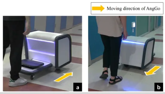
The second experiment was conducted with other researchers. The influence of personal mobility vehicles (PMVs) has been expanding into the indoor context, and the shift from personal vehicle ownership to shared mobility is underway. Thus, a new method for user-vehicle interaction is needed. The following and blocking methods were proposed previously for changing the driving mode of AngGo, a shared indoor smart mobility (SISM) vehicle; however, these methods were not evaluated. We evaluated both these methods' workload, added visual and auditory feedback, and validated their effects through a user-based study. Our study reveals insignificant differences between the workloads of the two mode-change methods. Auditory feedback shortens the reaction time as the user cannot recognize whether AngGo detects the user or not. Visual feedback is significantly preferred to auditory feedback, while bimodal feedback is more intuitive than auditory feedback. Our findings contribute to the interaction design considering shared PMVs in an indoor context.
Figure 9. Visual feedback using LED strips inserted right below the seat
(a) Visual feedback for the following method, (b) Visual feedback for the blocking method
Test environment
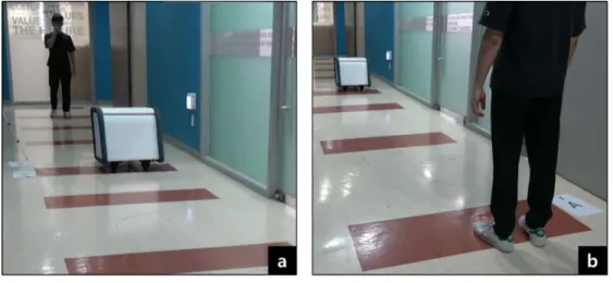
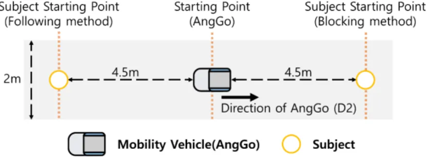
Our experiments are similar to the context of the natural interaction experiments. AngGo is placed 4.5 m from each participant before the start of each experiment. The sunlight is entirely blocked, and all ceiling lights are turned on in the hallway. The noise level is controlled within 40–50 dB, and the auditory stimulus reaches approximately 70 dB. The experiment environment's width and height are 2m and 10 m, respectively (Figure 10, Figure 11). We recorded a video of each subject to obtain a reaction time, which is when the time feedback appeared when the subject started to move. To record the participants' activity, the camcorder was placed at the center of the hallway.
Figure 10. Map of the test environment and the initial location of AngGo and subject
Figure 11. Test environment
(a) Visual feedback for the following method, (b) Visual feedback for the blocking method
Modality Reaction Time
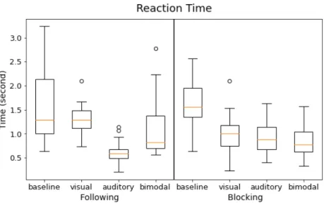
The participants' reaction time was measured by analyzing a video frame from the time the feedback was revealed to the moment the subject tried to move the participant's foot. The frame per second of the camcorder used was 29.97. Four participants were excluded because of the missing values due to video problems. The feet were not adequately captured. The box plot of the reaction time is shown in Figure 12.
The reaction time by feedback was statistically compared among 16 participants using the repeated method ANOVA for both mode-change methods. Results of Mauchly's test showed a violation of the sphericity assumption for the input reaction time in the following method (p = 0.007). Therefore, we used Greenhouse-Geiser correction to adjust the degree of freedom in the following method (ε = 0.665). We used the Tukey correction for all posthoc tests to prevent inflation of the type-I error.
Figure 12. Box plot for reaction time, bimodal (visual&auditory), o = outliers
Focus Group Interview: AngGo Developers
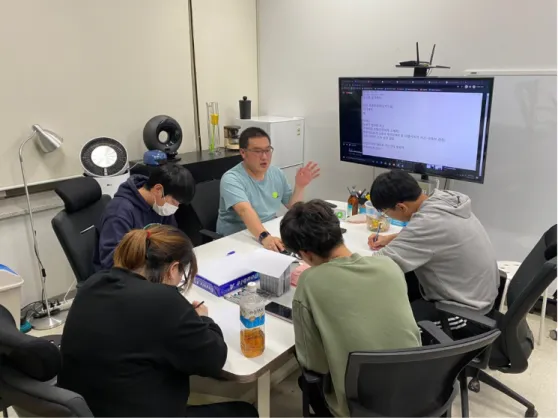
Before entering revision, the AngGo, we gathered four people who experience mobility development from 6 months to 24 months. The form of the workshop has an open question structured workshop, and it took around 90 minutes. One designer and three engineers participated in this experiment.
Research Question
The interview had an open question workshop, so we settled on two big research questions. Each member was asked to write their own opinion on paper. After they wrote opinions about the research question, they proposed their ideas to everyone. By generalizing all answers, we converge all ideas and research questions in these two. 'How to improve the acceptance of the SISM?' and 'What is the needed design implication of SISM?'
Figure 13. Interview with AngGo Developers
Aesthetic Design Mood board
We selected about 100 images via Red dot Awards and Behance. During this workshop, we asked participants to select the most proper moods for the SISM product. Results of the mood board are in Chapter Five, Design Features section.
Select Key Words
During the interview, we recorded all discussions and wrapped up writings. After we listened and saw through all the interview results and made a keywords list, all keywords are frequently used by participants. Results of extracted keywords are in Chapter Five, Design Development Procedure section.
Interview Discussion
All developers discussed two research questions. From every discussed topic, we extract seven vital critical points to be improved.
1. It needs a different posture in use. Users slightly bent when in use, so it needs to be hidden or make a different posture.
2. It needs robustness. Every mobility needs strong credibility to use.
3. It needs stability for users and pedestrians. Since it moves at a certain speed indoors, people should know its safety in design.
4. It needs to be sat posture for users. When users ride at more than a certain height, they are more at risk of being dropped.
5. The users do not ride or get off in the side of mobility. When the user rides on the left or right side of mobility, it gives feelings of falling.
6. The size of mobility should be compact for indoors and drive experience.
7. Information about the speed of mobility should be given to users.
Mechanical Review
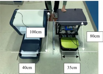
The AngGo has two different versions of the prototype. Two prototypes have similar structure and weight, but it shows differently when in autonomous mode. The prototype shows a smooth turn for evading obstacles, but the second prototype shows difficulties in use. This analysis's purpose was to discover the factors that affect the drive. The first different factor of the two prototypes was the position of the casters. The prototype has a shorter interval between casters than the second prototype. The second difference between the two prototypes was the wheelbase difference. The wheelbase is the distance between front-wheel center points and back wheel center points. The prototype has 58cm, and the second prototype shows 78cm. (Figure 14) The AngGo induces rotation by reducing the speed of rotations of the wheel located in that direction and increasing the speed of rotations of the opposite wheel. Since the rear wheel is an in-wheel motor, the caster, which is the front wheel, moves with force from the rear wheel's frame. The caster is not connected to the motor and steering-related devices. A caster whose wheel is rotated 360 degrees was used to align it for various driving. Therefore, it was judged that the essential point is how quickly and accurately the casters are aligned in the desired direction. First, to analyze the rotation, we analyzed the left and pure rotations. When rotating, the next rotation should be made due to the rotation speed difference on both sides of the rear wheel. The yellow dot in Figure 15 becomes the center of rotation at the beginning of the rotation, which requires rotation in a vertical direction in proportion to the front wheel's distance. (Figure 15)
Figure 14. The first and second prototype (left: second prototype, right: first prototype)
40cm 35cm
80cm 100cm
In this way, as the distance between the front wheels increases, the speed required for the left front wheel decreases, and the right front wheel's speed increases. However, since the force exerted on the front wheel by the frame is relatively constant, alignment in the rotation direction is achieved after both samples have had a similar time. Therefore, it is expected that in the structure where the difference in speed required for the front wheels is severe, further repulsion will occur, and rotation, as desired, will not be achieved.
Another different factor of the two prototypes was wheelbase. The longer the wheelbase, the larger the turning radius. In other words, mobility should rotate at a larger angle. Therefore, the rotation radius becomes large, and the movement becomes dull. Therefore, driving can be difficult. Instead, it is advantageous for driving stability and ride comfort and has the advantage of good straightness due to increased inertia for going straight. However, because the turning radius is large, and the inertia goes straight, users may feel difficult and dull in driving. It also has the disadvantage of low turning ability. This can be supplemented by shortening the rear overhang.
Figure 15. The speed induced in each wheel during rotation
Findings
The objective of the thesis is to create a SISM system. We devised, analyzed a seated platform, planned, manufactured the platform, and developed a prototype that implemented the configurations and desired functions of SISM. An observational experiment was carried out in the building's lobby or hallway to test both the autonomous mode. The AngGo platform moved in search of potential users and the manual mode, in which the rider drove it with a pedal plate.
Based on this experiment's results, we established a set of optimized parameters and adjusted performance accordingly. Shared services have emerged as a means of using PMVs. More research is required to understand the optimum design of natural interaction, specifically for indoor contexts that leverage visual or auditory feedback. The natural interactions of AngGo, following and blocking, are studied from two perspectives: workload of input modality and useability of output modality. Results confirm that both the following and blocking methods exhibit insignificant workload differences. We then recognize that unimodal auditory feedback is less preferred, flattering, and comfortable over visual feedback and is less preferred and intuitive than visual-auditory bimodal feedback. The reaction time is shortened by unimodal auditory feedback.
We suggest that natural interaction with the SISM vehicle can be improved by adding a visual modality, removing the risk of conflict, and informing whether an object is detected. Findings will contribute to the natural interaction design of service robots and shared PMVs considering an indoor context. The AngGo should be the compact size of wheelbase in autonomous mode for evading obstacles. To increase the drive experience of users, the longer wheelbase will be right.
However, for autonomous mode, the shorter wheelbase is proper to dodge other obstructions.
Summary and Findings
1. Next-generation of AngGo should give robustness and safety experience to the user in design aspects. It should improve the riding experience, exterior material, and height.
2. Next-generation of AngGo should have a compact size for the autonomous mode in mechanical aspects. AngGo should be improved in terms of size, height, and wheelbase problem.
4
AngGo-N
Design Features
Three Types of Operating Mode
Mechanical Structure
Prototype Development Procedure
Supplements and Findings During Development
AngGo-N
Design Features
AngGo-N is the Shared Indoor Smart Mobility platform, which helps users go to the designated destination by steering. The platform is intended to improve the efficiency of the time and energy of users. AngGo-N provides three types of operating modes. It usually requires self-driving to find the passengers. Alternatively, it could be a comfortable chair for users who needs rest. If a user wants to control mobility, they can also operate the AngGo-N with their foot. Therefore, switching is an essential part of use. We make a system diagram and sensors to discern between chair mode, control mode, and destination mode. Finally, we suggest foot steering as a new way of steering. We called it footstep steering because a user needs to step on the pedal plate to control the mobility. It might be a new steering system.
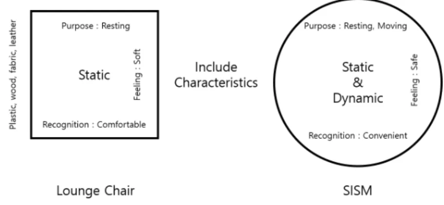
The lounge chair has made of plastic, wood, fabric, and leather. This material gives the user a soft feeling. The users use this chair for resting and recognize this as a comfortable thing. AngGo-N is SISM, which has dynamic characteristics. This has far different from static. To include the lounge chair, sofa's feeling in AngGo-N, we choose similar materials and functions with lounge chair. At the same time, we propose to use a different steering system to make a difference between SISM and electric scooters or electric wheelchairs.
Figure 16. Features and Characteristics of the lounge chair and SISM
Aesthetic Mood Boards of the AngGo-N
In the workshop, we requested to select which mood will be preferred for SISM. These are selected mood board images by all participants. Extracted factors were applied to AngGo-N.
Figure 17. Design Mood board of AngGo-N
STK_01 by Pranab P Kumar DAYBE SOFA by Luka Spasojevic
TimetoToast by Lee Sungwook Vistic by Areum Gu
Coway FAB by OFFOF co Smart Infant Carrier by ZAAFDesign
Beoplay home set by Bang and
Olufsen Black Pears by Dim Eysner
Concept Keywords of the AngGo-N
Compact; Reliability; Riding Experience; Soft; Indoor.
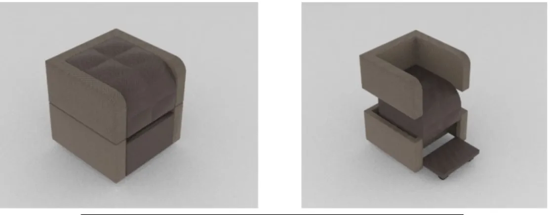
Concept of AngGo-N
The basic Concept of AngGo-N is giving comfort to users who board. AngGo-N has a compact size during the semi-autonomous driving mode. In this mode, AngGo-N finds other users indoors.
When users about to ride AngGo-N, they sit in the center block. The center block seat parts are slightly going down, and the armrest, the backseat is coming up to support the user.
Simultaneously, to make the wheelbase longer, the footrest part folded out to support the user's foot.
Figure 18. Concept Modeling of AngGo-N
Figure 19. User Posture in use (User model height was 170cm) (left: the autonomous driving mode, right: the manual mode)
Three types of operating mode
AngGo-N provides four types of operating modes. The modes can be changed by each other. First, Autonomous mode supports finding potential users to use AngGo-N. When AngGo-N and the user interact and recognize that a user will sit via voice, gesture, or action, AngGo-N enters Standby mode. In this mode, the user can sit and take a break on AngGo-N. When the user control AngGo-N with step pedal control, AngGo-N enter Journey mode. In Journey Mode, AngGo-N decides to enter standby mode or autonomous mode based on pedal control or seat switch (Figure 21).
As mentioned above, AngGo-N enables a user to select different modes. 6 ToF(Time of Flight) sensors are installed to detect obstacles and pedestrians. The general location of the ToF sensors is described in Figure 20. Each of the ToF sensors can detect 2 meters and have 27 degrees of Field of view(FoV).
Figure 20. ToF description of AngGo-N
Figure 21. AngGo-N mode scenarios
Autonomous mode
In autonomous mode, as AngGo-N do Self-driving, the mobility moves around the lobby of the building and find potential users to use AngGo-N. If the batteries lower than a specific voltage, it automatically finds a charging station nearby. During autonomous mode, it could receive a request from another user to ride. If AngGo-N receives the request from users through the application, it travels toward the user. Before AngGo-N interacts with the user who sends the request, AngGo-N denies other user's interactions.
Standby mode
In standby mode, AngGo-N's in-wheel motor tries to stop. Users can ride on and take a rest or control the foot pedal. After user control or make an input on foot pedal panel, AngGo-N enter to manual mode. If the user inputs destination through application to AngGo-N, it enters to destination mode. When the user stands up from AngGo-N, the seat switch will recognize the user's absence. After a few seconds, AngGo-N enters Autonomous Mode.
Journey Mode
AngGo-N moves toward the destination, which is entered by the user who sits on mobility.
AngGo-N moves through the pathway to the destination. During travel, AngGo-N avoids obstacles and pedestrians who are detected by 6 ToF sensors. Users sitting on AngGo-N can control mobility through a foot pedal plate. The distance of two feet of the user makes different input to two in-wheel motors. Steering of mobility is an important activity to ride on. However, for SISM, traditional steering is still insufficient. Mostly, there is no optimal standard way to control PMVs. We saw deep inside of steering way.
All traditional ways to control or steering mobility have strong and weak points to apply to SISM.
In this paper, we follow the form of the sofa. Therefore, we consider relevant steering for AngGo- N with two feet. The most basic criterion criteria are from sitting sofa on AngGo-N. in this stable state. We consider new ways of steering mobility in the indoor environment. Finally, we can suppose step steering. Based on the foot control method, we apply a different control method for AngGo-N.
Figure 22. control method description
Figure 23. Distance sensor description ToF Sensor
Distance between Foot and IR sensor
D1 Direction
D2 Direction
Two of the ToF sensors are located on the surface of the footplate in AngGo-N. ToF sensors measure the distance between the foot and the surface of the footplate. The distance information goes directly to in-wheel motor rotation speed. When calculating the value of a distance sensor at a given measurement location during a stopped state by (𝑆𝑆���𝑛𝑛 ), and the value of the distance measured by 𝑆𝑆𝑛𝑛, then the distance change ratio (𝛿𝛿𝑛𝑛) required for motor output can be generated using (1) and (2). The equation is used for the left side motor drive unit (left side motor and right ToF) when n = 1 and for the right side motor drive unit (right side motor and left ToF) when n
= 2. AngGo-N's movement follows (2) (See Table 2 and Figure 24):
𝛿𝛿𝑛𝑛=�
−1, 𝑆𝑆𝑛𝑛< εnS
|𝑆𝑆𝑛𝑛− 𝑆𝑆���𝑛𝑛|
Max|𝑆𝑆𝑛𝑛− 𝑆𝑆���𝑛𝑛|, 𝑂𝑂ℎ𝑡𝑡𝑡𝑡𝑡𝑡𝑡𝑡𝑡𝑡𝑡𝑡𝑡𝑡 (1)
where
𝛿𝛿𝑛𝑛≜ distance change ratio;
𝑆𝑆𝑛𝑛
��� ≜ distance in the off state (cm);
𝑆𝑆𝑛𝑛≜ the distance measured by the sensor (cm);
εnS
≜
foot and ToF sensor distance threshold(short);The AngGo-N determine to move or not based on the value of 𝑑𝑑𝑚𝑚. If this value is 1, AngGo-N moves. In the case of 0, AngGo-N determines to stop.
𝑑𝑑𝑚𝑚 = �1, εnS < min(𝛿𝛿𝐿𝐿,𝛿𝛿𝑅𝑅) <εnL
0, otherwise , (2) Where
𝑑𝑑m ≜ determination of movements;
𝐶𝐶s≜ motor stopping distance threshold;
εnL
≜
foot and ToF sensor distance threshold(long);The control signal (𝑃𝑃𝑛𝑛) for the motor drive unit that is operating the wheel motor is calculated by (3):
𝑃𝑃𝑛𝑛 =𝛾𝛾𝑛𝑛𝛿𝛿𝑛𝑛 , 𝛾𝛾𝑛𝑛 > 0 (3)
where
𝑃𝑃𝑛𝑛≜ motor control signal;
𝛾𝛾𝑛𝑛≜ velocity control constant;
Table 2 and Figure 24 describe the movement of the AngGo-N equation. Value E is the experiment decided value that user press the foot pedal proper amount of weight to move 𝐷𝐷2.
Table 2. AngGo-N manual mode example equation
𝜹𝜹𝟏𝟏 𝜹𝜹𝟐𝟐
Stop E < 𝛿𝛿1< ε1S or 𝛿𝛿1> ε1L E < 𝛿𝛿2< ε2S or 𝛿𝛿2> ε2𝐿𝐿
Move to 𝑫𝑫𝟏𝟏 ε1S< 𝛿𝛿1<ε1L ε2S<𝛿𝛿2<ε2L
Move to 𝑫𝑫𝟐𝟐 𝛿𝛿1< E 𝛿𝛿2< E
Turn clockwise 𝛿𝛿1< 𝛿𝛿2
where 𝜀𝜀1𝑆𝑆<𝛿𝛿1<𝜀𝜀1𝐿𝐿 and 𝜀𝜀2𝑆𝑆<𝛿𝛿2<𝜀𝜀2𝐿𝐿
Turn counterclockwise 𝛿𝛿1> 𝛿𝛿2
where 𝜀𝜀1𝑆𝑆<𝛿𝛿1<𝜀𝜀1𝐿𝐿 and 𝜀𝜀2𝑆𝑆<𝛿𝛿2<𝜀𝜀2𝐿𝐿
where 0 < E < 0.3, (n = 1, 2) , (S = Short range, L = Long range)
Figure 24. AngGo-N movement based upon the given equations
Scenario of AngGo-N
AngGo-N wanders around of stated inside of the building. When AngGo-N encounters a user who wants to use it, AngGo-N interacts with users, and the user sits down on the seat. When the user sits down, the seat part touches the seat switch of AngGo-N, and it tries to stop the fixed position by controlling two in-wheel motors. When the user interacts with AngGo-N, it moves as user input through pedal plates.
Figure 25. AngGo-N system diagram
Systems of the AngGo-N
The overall system follows AngGo's system (Figure 27).
Figure 26. User scenario of using AngGo-N in the indoor building
Figure 27. AngGo-N block diagram
Figure 28. Implementation of electric components of AngGo-N in real size of foams
Figure 29. Implementation of electric components of AngGo-N Distance Sensor
6 ToF Sensor
Sit Switch
Power Switch
MCU
2 Motor Drivers
Motor and MCU Battery
Mechanical Structure
AngGo-N has transformation aspects. Based on transformation design, we followed three conditions in papers. [35]
1. Transformable design can transform from one state with its functionality and physical form to another state with another functionality and physical form. Two or more of these individual states can exist.
2. Product transformation must be intended in the design process.
3. The deformation must be reversible, and the product is not separated.
Based on three conditions and interim results, we make the most compact aspects design in a box shape for testing outcomes of overall ideas.
Figure 30. AngGo-N first mechanical concept model
①
②
③
④
① The back of the chair should exist at a certain height. We found various references in IKEA indoor and outdoor back of chair height and apply 75 cm from the seat.
② In moving personal mobility, the foot should be on the reliable plate. For the user, the front panel is folded out to support the footplate.
③ The wheelbase should be short of making the radius of rotation small. During autonomous mode, the front-wheel plate folded, and it makes the wheelbase shorter than manual states. In manual mode, a longer wheelbase enhances the driving experience than the short one.
④ The user's sitting posture to ride AngGo-N is similar to a sofa that users usually encounter in their living room or indoor. They could ride AngGo-N as they sit down on a usual sofa in front.
Mechanical Structure Analysis
AngGo-N is designed so that the backrest structure and footrest structure come up and forward, respectively, as the person's weight lowers the chair seat. There is a total of two parts, a gear structure that connects the seat and back structure and a gear structure that connects the seat and footrest structure. They are designed to increase the displacement compared to each gear's seat having a 1 to 5 radius ratio difference.
The minimum load to move the backrest structure was calculated by creating a force equation between the seat and the backrest structure. However, since the two gear parts have to rotate only by the seat's movement and move the footrest and the backrest, we will calculate by solving the force equation reflecting the relationship between the three parts.
First, since 20° is the industry-standard value for the normal spur gear pressure angle, it was assumed a pressure angle of 20° for all racks and pinions. Besides, AngGo-N consists of 4 parts in total: seat part (1), back part (2), footrest part (3), and body part (4), and these parts are the friction force between the rack and pinion and the floor (vertical drag). All forces except for are assumed to be zero. Finally, all structures were assumed to be parallel or perpendicular to each other. Each part was weighed using a force gauge.
Figure 31. Force gauge measurement
L≜ Human weight
𝑊𝑊𝑆𝑆 ≜ Seat part weight =185N
𝑊𝑊𝐵𝐵 ≜ Backrest part weight =109.167N R ≜ Radius of large gear
𝑡𝑡 ≜ Radius of small gear
𝐹𝐹𝑆𝑆𝐵𝐵 ≜ The force between the small gear on the seat part and the rack on the body part 𝐹𝐹𝑆𝑆𝑆𝑆≜ The force between the rack in the seat part and the small gear in the body part 𝐹𝐹𝐿𝐿𝐵𝐵≜ The force between the large gear in the body part and the rack in the backseat part 𝐹𝐹𝐿𝐿𝐿𝐿 ≜ The force between the large gear in the body part and the rack in the footrest part 𝑓𝑓 ≜ Friction force between the footrest and the floor=22.5N
Figure 32. Equation definition description 1
𝑓𝑓 𝐹𝐹𝐿𝐿𝐿𝐿
𝐹𝐹𝐿𝐿𝐵𝐵 𝐹𝐹𝑆𝑆𝑆𝑆
𝐹𝐹𝑆𝑆𝐵𝐵
(left: the autonomous mode, right: the user manual mode)
𝑊𝑊𝐵𝐵
L
𝑊𝑊𝑆𝑆 𝑅𝑅
𝑡𝑡
Figure 34. Structural change by sitting, front view
Figure 35. Structural change by sitting, side view (left: the autonomous mode, right: the user manual mode)
(left: the autonomous mode, right: the user manual mode)
Figure 36. Gear Information [40]
form Module Number of Teeth
Shaft hole diameter Ph7
B Reference circle diameter
d
End circle diameter
D
Tooth root
G
H L l1 l2 Allowable transmission
power
Small
gear 2.0 22 8~25 20 44 48 39 36 34 14 7 29.21
Large
gear 2.0 100 20~55 20 200 204 195 70 34 14 7 148.44
Figure 37. AngGo-N Gear Information Detail [40]
Moment equation of seat part gear axis,
𝐹𝐹𝑆𝑆𝐵𝐵𝑅𝑅=𝐹𝐹𝐿𝐿𝐵𝐵𝑡𝑡
Moment equation of body part gear axis,
𝐹𝐹𝐿𝐿𝐿𝐿𝑅𝑅=𝐹𝐹𝑆𝑆𝑆𝑆𝑡𝑡 Force equation of seat part y-axis,
Force equation of Backrest y-axis,
−𝑊𝑊𝐵𝐵+𝐹𝐹𝐿𝐿𝐵𝐵 𝑐𝑐𝑐𝑐𝑡𝑡 20 = 0 Force equation of pedal part x-axis,
−𝐹𝐹𝐿𝐿𝐿𝐿 cos 20 +𝑓𝑓= 0
Force equation of Body part y-axis,
−𝐹𝐹𝑆𝑆𝑆𝑆𝑐𝑐𝑐𝑐𝑡𝑡 20− 𝐹𝐹𝑆𝑆𝐵𝐵cos 20 +𝑁𝑁= 0 Based on Figure 37,
𝑅𝑅=�200
44� 𝑡𝑡= 4.55𝑡𝑡 𝑓𝑓=𝐹𝐹𝐿𝐿𝐿𝐿 cos 20 = 0.22 𝐹𝐹𝑆𝑆𝑆𝑆 cos 20 𝑊𝑊𝐵𝐵=𝐹𝐹𝐿𝐿𝐵𝐵 𝑐𝑐𝑐𝑐𝑡𝑡 20 = 0.22 𝐹𝐹𝑆𝑆𝐵𝐵 cos 20 𝐿𝐿+𝑊𝑊𝑆𝑆=𝐹𝐹𝑆𝑆𝑆𝑆𝑐𝑐𝑐𝑐𝑡𝑡20− 𝐹𝐹𝐿𝐿𝐵𝐵cos 20 +𝐹𝐹𝑆𝑆𝐵𝐵cos 20
= 4.55𝑓𝑓 − 𝑊𝑊𝐵𝐵+ 4.55𝑊𝑊𝐵𝐵
𝐿𝐿= 4.55𝑓𝑓+ 3.55𝑊𝑊𝐵𝐵− 𝑊𝑊𝑆𝑆= 4.55(22.5) + 3.55(109.167)−185 = 304.917 [𝑁𝑁]
As a result of the force gauge experiment, L came out as 440N, and there was a difference of 135.083N. This error is due to the use of an ideal assumption. It is assumed that it is due to several reasons, such as frictional force with the pipe when gear part and rack movement.
Prototype Development Procedure
With real size structure and information in IKEA and Size Korea, we make a frame of AngGo-N.
Up and down motion was held by the current chair and finalized the frame's size, including exterior panel thickness. To reinforce the aluminum profile, we cut an aluminum plate and attach each part. (Figure 38) After deciding the frame's exact size, we make an initial frame and attach a guide pole for the backrest and foot pedal parts. (Figure 39) At the same time, the rear overhang was too long for mobility. Within the structure, we made a new fork for an in-wheel motor fork with an aluminum plate. (Figure 40) two of the fork parts consist of a joint structure that makes the fork hold the structure and in-wheel motor simultaneously.
Figure 39. the initial stage of the frame
Figure 40. Reinforced wheel fork of AngGo-N
Exterior Design Procedure
The exterior design part consists of a wood panel. The backrest part was covered with fabric cover on the wood plate. Each wood plate was treated with stain and varnish. After drying all plates, each plate is attached to the frame of AngGo-N (Figure 44). Seat parts of AngGo-N have consisted of two parts. One of the seat parts is for fastening the cushion and body frame of AngGo- N. The second seat part has fabric to give a cozy feeling to the user (Figure 45). For colors of AngGo-N are decided based on the combination of the axis of wood parts and fabric parts (Figure 41). The fabric has a similarity with the materials used on the sofa. Wood parts were processed by stain chemicals (Figure 44). Dual lock tape makes the frame and exterior plates stick together.
The seat parts were consisting of two different parts. One for hold frame with seat load distribution part, and another part hold cushion of the seat (Figure 42, Figure 43).
Figure 42. Exploded image of AngGo-N
Figure 43. Assembled image of AngGo-N
Figure 44. Fabricating process of Exterior plates
Figure 45. Parts assemble process
Seat Part Assemble
The seat part will encounter the user's weight and gear movement. To make sure this all part work smoothly, we attached six compartments to joint body and seat part. On the top of the seat part, we attached a 50mm sponge to give the user a comfortable feeling about AngGo-N. Before we assemble sponge and fabric parts, we make a structure to make forms in a specific area. All the shapes were in a box shape, and we give two brown side plates to give users intuitively know the seat part area. The seat compartment size was coming from the IKEA sofa seat size.
Figure 46. Seat Parts assemble process
AngGo-N prototype
The outcome of the prototype is in Figure 47. Within the indoor environment, it gives a similar feeling to the lounge chair. Exterior plates hide two casters and in-wheel motors. The raised backrest makes the assistant elbow rest part elevate together. At the same time, the footplate holds the user's foot. Users can hold or lean to one of the compartments to rest on SISM mobility. After the rider gets off SISM mobility AngGo-N, all the compartment goes down and folds to become the square shape of AngGo-N.
Figure 48. AngGo-N finished prototype (Standby and Journey Mode)
Supplements and Findings During Development
Mood board supplements
On the mood board, the product phenomenon, appearance, and feeling must be connected by a form factor. All factors that affect the product have to be segmented by problem definition, user investigation, and analysis. Based on segmentation, design requirements are coming out.
Functional requirements are related to function and performance. Ergonomic(useability) requirements are relevant to usability, and symbolic requirements are related to the appearance, sense, and feeling of products. The functions and performance make the specification of products.
Based on target analysis, the metric and volume came out. Functional requirements are solved by structure and technical improvement. Ergonomic requirements have consisted of convenience, interface, and interaction of products. Symbolic requirements make a proper aesthetic appearance and CMF related to the target or class of users. Here mood board or imageboard can be applied to the product development procedure(Table 3).
Target Analysis
It should have been decided who is the target user of AngGo-N. The specific target users' needs to be investigated. It needs to set a target, keywords, and concepts. Based on target analysis, the overall shape, detail features, and CMF can be matched with target and AngGo-N.
Table 3. Requirements of personal mobility
Requirement Specification Metric Volume Reference
Functional Requirements
Personal mobility is transformed based on target
users' height and weight.
Height cm 168.5
[45]
Weight Kg 64.3
Ergonomic Requirements
When a user approaches mobility, it must stop.
Distance between the user and personal mobility
cm 75 -
Symbolic Requirements
Have a modern look and match the
interior.
Mood Board Form Factor
CMF
- - [44]
5
AngGo & AngGo-N
Concept and Platform Comparison of Two Model
Main Research Questions
Expected Contribution
AngGo & AngGo-N
Main Research Questions
Our primary research question was to know 'how to improve the acceptance of the SISM?' and 'what is the needed design implication of SISM?'. We have developed AngGo and AngGo-N to research the possibility and functional aspects of usual users to know this central research question.
We will go through competitive testing and value opportunity analysis about two platforms with two developed personal mobility.
Competitive Testing and Value Opportunity Analysis
All the experiments were held in the safety area, did not restrict other pedestrians by caution, or installed warning signs during the experiment. The AngGo-N and AngGo were placed, and all the participants to be a user and pedestrian. This makes participants fully understand and pre- step to give value Opportunity analysis after that. The form of experiments is based on competitive testing [25]. This is the process of researching to evaluate the useability and learnability of competitors' products. [39] The process of AngGo and AngGo-N includes monitoring participants. We want to know the opportunity to assess two SISM platforms from the end user's point of view through competitive testing. All participants were recruited from significant design students or related. We let all participants be aware of the potential for bias between two platforms.
After participants use two platforms, we tracked and compared the interaction and reaction of them. Competitive testing results include insights from competitive platforms, and these results were collected through Value Opportunity Analysis. Value opportunity analysis maps the extent to which a products' aspirational qualities align with people's idealized lifestyle or a fantasy version of themselves[39]. This experiment proves with a list of value-based criteria or value opportunities.
There were seven value opportunities, and we revised them to fit two SISM platforms in six lists.
In emotion criteria, 'adventure, independence, sensuality, confidence, and power.' Aesthetics case, 'visual and tactile' was selected. Identity has 'point in time, sense of place, and personality. For ergonomics, 'comfort, safety, and ease of use' were asked. In the last criteria, quality has
'craftsmanship and durability' listed. The instructor discussed all the listed words' exact meaning in this experiment to make the same understanding between them [26].
Figure 49. Value opportunity analysis meaning [26]
After Competitive testing, all participants were asked to answer this questionnaire. This method is one of the best uses for the VOA to measure how our product stacks up to competitors' products in terms of perceived value to the audience [39] (Figure 50).
All interviews were conducted through a google questionnaire. The participants only enter their code to distinguish between them and input what they experienced.
Expected Contribution
AngGo and AngGo-N were born based on design process and experiments to know acceptance of SISM concept and platform to usual users. We expected that this research question and experiment verify the needs of SISM and the primary form of sit type platform for SISM.
Figure 50. value opportunity analysis for SISMs answer mean value and criteria AngGo
Mean Value
AngGo-N Mean Value
Ergonomics
6
Discussion
Important Factors in SISM
Discussion
Further work and Limitation
![Figure 2. Experiment procedure [9]](https://thumb-ap.123doks.com/thumbv2/123dokinfo/10491520.0/17.774.152.622.279.557/figure-2-experiment-procedure-9.webp)
![Figure 8. Rider posture when in use[38]](https://thumb-ap.123doks.com/thumbv2/123dokinfo/10491520.0/26.774.109.677.612.930/figure-8-rider-posture-when-in-use-38.webp)