The results and findings of this study show that the magnetic induction produced by the steel core in ACSR (aluminum conductor, steel reinforced) conductors causes an increase in the alternating current losses, the associated alternating current to direct current resistance ratio and the effective alternating current resistance of the conductor, while the conductor is live during normal operation. By manipulating these factors it was found that the total effective AC resistance of the conductor could be significantly reduced at higher load currents.
INTRODUCTION
- Background
- Motivation for the research
- Primary Research Objectives
- Research Methodology
- Research Scope
- Post Research Objectives
- Definition of Key Terms
The specific results of this research study were to determine if the effective AC resistance, ac-dc resistance ratio and AC power losses of ACSR overhead conductors can be reduced by changing the lay ratios or lay lengths of the colored/metallic layers of the wires of aluminum that make up the ACSR conductor. Using the developed software simulation program (i.e. research tool) that determines and calculates the interactions between variations in span length (span ratio) and its effect on AC resistance for multilayer ACSR conductors, it can be predicted quite accurately the expectation. Electrical power losses based on the total effective AC resistance of the conductor.
LITERATURE REVIEW: SUMMARY
The later paper by Morgan and Price [6], which was based on the 'corrected' model developed by Barrett et al. [7], aimed to investigate the effect of core temperature and total load current on the AC-dc resistance ratio, magnetic power loss in the core and the power losses caused by the redistribution of the aluminum layer currents, for a 3 layer ACSR conductor. Increasing the core temperature causes a redistribution of the current density between the 3 layers of aluminum wires, resulting in an additional current loss.
THE COMPUTER SIMULATION MODEL
Introduction
Background
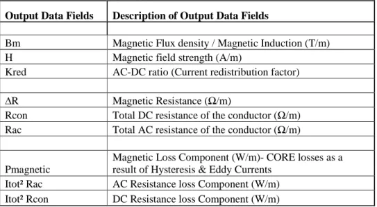
Data Inputs and Outputs
- General Input Data
- General Output Data
The detailed results of the key computer-simulated scenarios and their analysis, as presented in Chapter 4, are based on the determination of these key output variables for each scenario. The determination of the set of optimized lay lengths was first based on compliance with the lay ratio constraints as detailed in IEC, i.e., the International Electrical Committee.
RESULTS AND FINDINGS
Introduction
Analysis
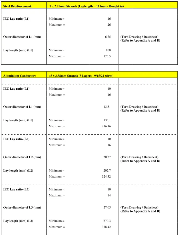
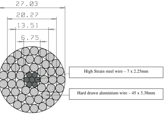
Using the developed software simulation program, several software simulation exercises were conducted for a set of different scenarios to ultimately produce a proposed set of optimized lay lengths/ratios for an identified ACSR survey contractor sample (ie TERN ACSR). Using the above parameters as defined in IEC, on a specific TERN ACSR conductor sample, the maximum and minimum lay lengths for each layer of steel and aluminum wires were calculated and shown in Table 4.2. Therefore, only the changes in the laying lengths of the aluminum wires of the different layers of aluminum that make up the conductor were simulated.
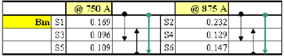
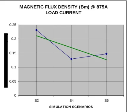
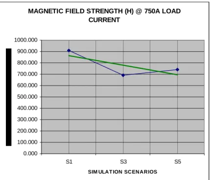
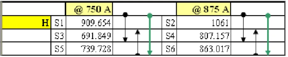
Since only variations in the lay lengths of the aluminum layers were simulated, there were only 8 permutations (i.e. A – H): in terms of the maximum and minimum lay ratio for the combinations of the lay lengths of the three layers of aluminum wires making up the TERN ACSR conductor. The computer simulations carried out to determine the optimized laying lengths/laying ratios were therefore simulated for these 4 scenarios and were mainly based on determining which of these scenarios resulted in the greatest reduction in terms of magnetic field strength (H), magnetic resistance (∆R) and magnetic core losses (Pmagnetic) at the maximum rated load current of 875 A and at a constant core temperature of 75 degrees Celsius. Having established a set of theoretically optimized lay lengths for reduced power losses, the next objective of this study was to determine and quantify the potential savings in terms of AC resistive losses if current TERN ACSR conductor lay lengths were used.
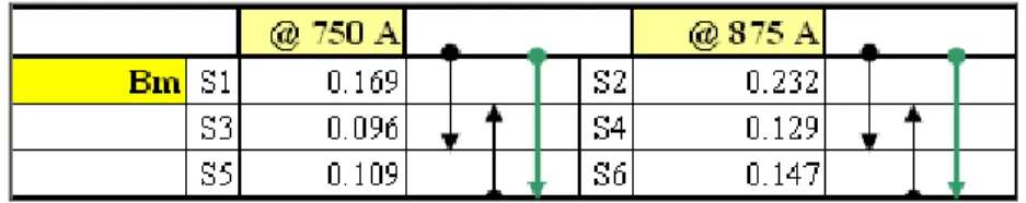
Computer simulations for scenarios 1 and 2 were performed on the TERN conductor sample with its current (Original) lay lengths for 2 different load currents (i.e. 750 and 875 amperes). These computer simulation results provided the baseline values of expected AC resistance and associated AC watt losses, for comparison of expected savings/reductions with these parameters, compared to the results obtained by the simulations for scenarios 3 and 4 (i.e. TERN conductor with 'optimized ' laying lengths for load currents of 750 and 875 amperes respectively). After determining what would be the optimum lay ratios for the 3 layers of aluminum wires for the TERN sample conductor (i.e. scenario D) and also determining the expected AC resistance and AC wattage losses for this lay ratio combination (as per computer simulation results for Scenario 3 and 4), the next objective of this research study was to determine whether these 'optimum' lay ratios/lay lengths ie.
Having established a set of optimized lay lengths for reduced power losses (i.e. scenario D), the next objective of this study was to determine and quantify the possible savings in terms of ac resistive losses if the current/original lay lengths of TERN ACSR conductor were modified/manufactured to the 'optimized' set of lay lengths. The intention behind performing computer simulations for scenarios 1 and 2 (ie TERN conductor with original lay lengths at load currents of 750 and 875A respectively) was to produce expected baseline values for the key data output parameters and more importantly the expected AC resistance and associated AC watt loss. The computer simulations performed for scenarios 3 and 4 (ie TERN conductor with optimized lay lengths/lay ratios at 750 and 875A respectively) were based on the optimized lay ratio combination originally reflected/identified for scenario D.
These 'Optimized Production Lay Lengths' were then used in computer simulation exercises for scenarios 5 and 6 (TERN conductor with Optimized Production Lay Lengths) and the associated AC watt losses were noted along with other key parameters.
Summary of Key Findings
The proposed set of optimized lay lengths (lay ratios) for the TERN conductor sample is therefore that of the 'Optimized production lay lengths' summarized and presented in Table 4.39 part C. The procedural analysis is based on the selection of this optimized set of lay lengths for the 3 layers of aluminum wires of the TERN ACSR conductor sample (the detailed computer simulations for this choice of optimized lay lengths, at load currents of 750 and 875 A have previously been shown for scenarios 5 & 6, the detailed results of which are reflected in Tables 4.13 and 4.14 respectively). It was found that the key parameters affecting the effective AC resistance were those of hysteresis and eddy current power losses and the redistribution of the layer currents for the TERN ACSR conductor sample, when the lay lengths of its aluminum layers were varied.
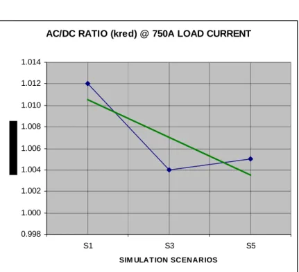
Due to the reduction in the effective magnetic induction in the steel core, the ac-dc resistance ratio [kred] showed a reduction from 0.69 to 0.98 % and the total ac power losses [Itot² Rac] were reduced as the load current was varied. It was also found that the AC resistance [Rac] of the TERN ACSR conductor sample can be reduced synonymously with that of the reduction in the AC power losses. Therefore, adding the conductor DC resistance value to the component resistances produced by the current redistribution and magnetic hysteresis & eddy current power losses forms the total effective AC conductor resistance.
This is in contrast to standard practice where conductor resistance values for AC and DC are assumed to be the same. Based on a 100 (one hundred) kilometer long double-circuit transmission line with one conductor per phase, the reduction in power loss would amount to The findings described above therefore confirmed the hypothesis of this research study and effectively fulfilled the objectives of this research study.
CONCLUSION AND RECOMMENDATIONS
- Introduction
- Research Findings
- Recommendations for Future and Further Research
- Conclusion
Using the developed software simulation program, a proposed set of optimized placement lengths (span ratios) was developed for the identified research sample of ACSR conductor. The scenarios for which each of the computer simulations were performed simulated what could be expected mainly in terms of electrical losses as a result of effective current resistance changes, changing or altering lay ratios or lay lengths, colors/metals. layers of aluminum wires that make up the ACSR conductor. Using the developed software simulation program (i.e. research tool) that determines and calculates the interactions between variations in span length (span ratio) and its effect on current resistance for multilayer ACSR conductors, it is now able to predict quite accurately. expected electrical power losses based on the total effective resistance of the conductor.
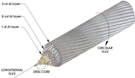
Having developed a proposal specifying optimal stretch lengths, for the TERN ACSR conductor sample, based on computer simulation, a recommendation for further research would be to manufacture TERN ACSR conductor using these 'optimized stretch manufacturing lengths' ', as presented in this research study. Factory trial and testing processes should then be applied to each ACSR conductor identified for span length optimization, as will be applied to the TERN conductor research sample. More specifically, the main parameters that cause this increase in the effective AC resistance of the conductor, as a result of the magnetic induction produced by the steel core, are those of hysteresis and eddy current power losses in the steel core and an increased power loss . caused by the non-uniform redistribution of current in the layers of aluminum wires, due to the 'transformer effect'.
Factors affecting magnetic induction include, among others; ferromagnetic properties of the steel core, physical construction of the conductor, operating temperature/conductor core, load current and power system frequency. A computer simulation program was developed to calculate the effective AC resistance of multilayer ACSR conductors and was mainly based on determining the impact of changing these main factors, evaluating its effect on the AC resistance of the conductor. The conductor sample used in this research study is commonly known as TERN ACSR conductor in the South African market and it was shown that by practical changes in the span ratios or lay lengths one is able to reduce the total effective AC resistance of the conductor and related power losses.
BIBLIOGRAPHY