CP Kloppers for help with writing, sample preparation and conducting the research. To develop ISM models, a cantilever geometry was used to determine inherent stresses resulting from the process parameters and the variation of the scanning strategy.
INTRODUCTION
- Problem Statement
- Aim
- Objectives
- Research Questions
- Research Method
- Experimental Procedure
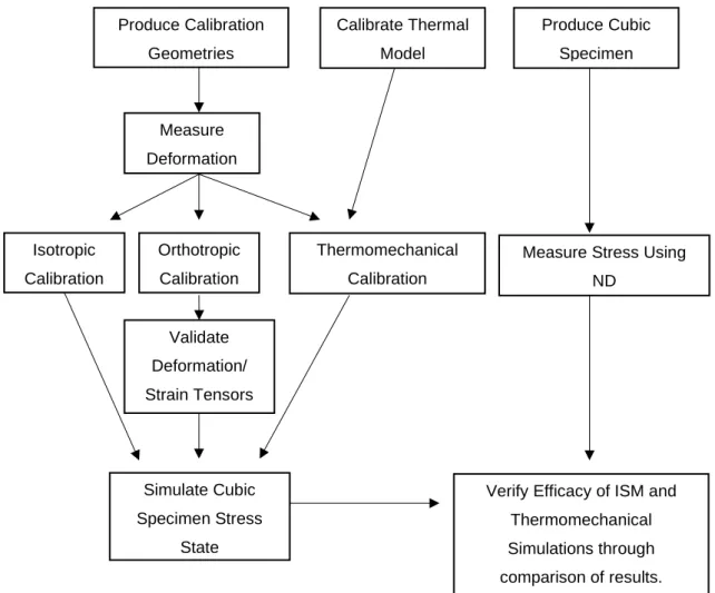
Simulate RS size and distribution of cubic samples for each case of the calibrated manufacturing parameters. This workflow was applied to assist in identifying the effects of the independent variable, HR, on RS, and to determine the effectiveness of the analytical methods in predicting RS conditions.
LITERATURE STUDY
Introduction
- Indirect Methods
- Fused Deposition Modelling
- Laminated Object Manufacturing
- Selective Laser Sintering
- Three-Dimensional Printing
- Direct Methods
- Electron Beam Melting
- Laser Metal Deposition
- Selective Laser Melting
Metal foil as a laminate allows the production of metal components in LOM, where the strength of the part depends on the adhesive used between the individual layers of laminate. For this purpose, a specialized sacrificial polymer is used in the SLS process, which is able to decompose in a post-sinter furnace, allowing the green part to maintain its structural integrity during sintering of the metal particles [13].
SLM Process Description
- Laser Parameters
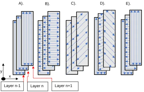
- Scanning Strategies
- Inconel 718 Properties
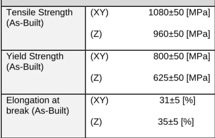
- Tensile Strength
- Ductility
- Elasticity
- Summary of Mechanical Properties
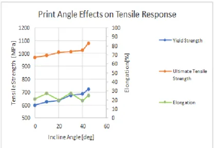
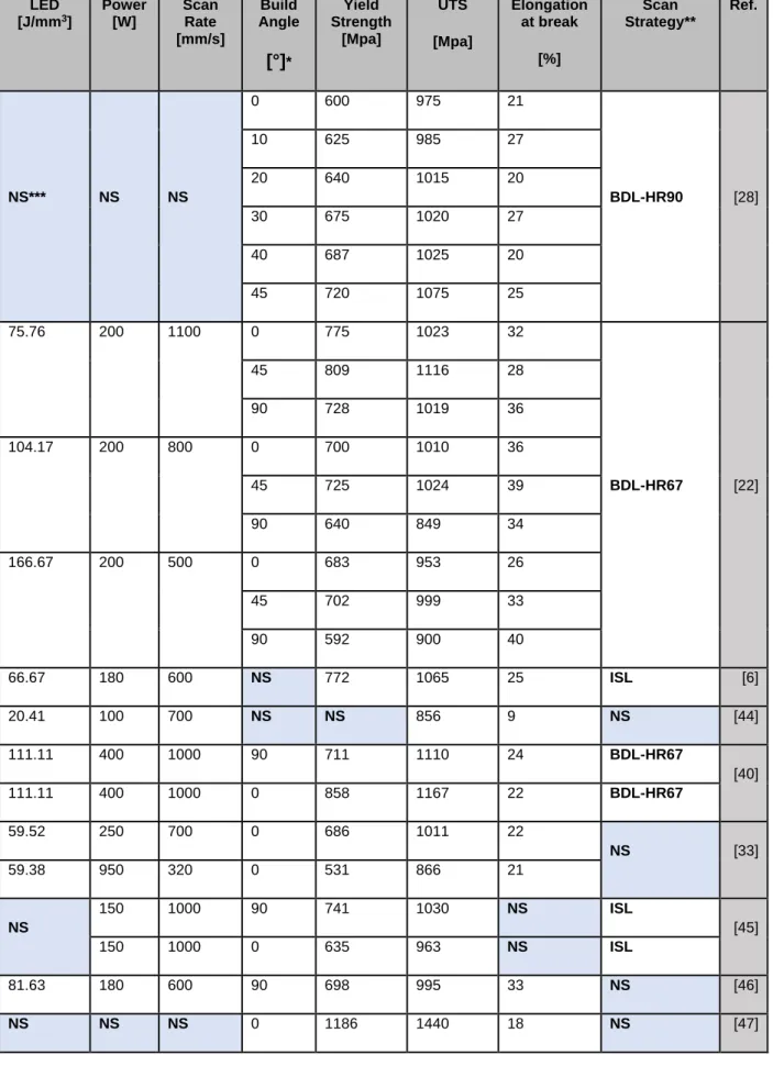
In addition to the build angle effects, the scan speed and laser power change the pull response of the SLM components and can be correlated using LED. Because the process parameters are interdependent for the production of a viable component, Table 2-3 provides a relative summation of the effects on the tensile properties of IN718 SLM components, as derived from the literature.
![Figure 2-3: Layer height, hatch spacing, and scan tracks of a single SLM layer (adapted from [15])](https://thumb-ap.123doks.com/thumbv2/pubpdfnet/10395669.0/23.892.151.751.529.782/figure-layer-height-hatch-spacing-tracks-single-adapted.webp)
Residual Stress Formation
- Scanning Strategy Effects
- Build Parameter Effects
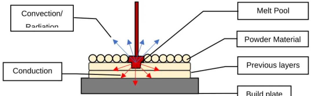
This causes the substrate to expand due to heat input while the molten material contracts due to solidification, leading to a compressive RS in the substrate and a tensile RS on the newly formed layer [7]. The tensile-compressive RS condition at the build plate interface is due to thermal conduction through this surface being greater than conduction through the powder material, or heat loss through convection and radiation (Figure 2-8) [37].
Residual Stress Determination
- Contour Method
- Inherent Strain Method
- Diffractive Techniques
Using the contour method, the static equilibrium RS boundary condition in the component is exploited. Research has also shown that the mesh becomes compromised during mechanical or thermomechanical simulations of the AM process.
Summary of Residual Stress
HR67 Note: * Method refers to how RS was determined by CM (contour method), THM (thermo-mechanical simulation) and XRD (X-ray diffraction). It is important to remember that CM can only measure RS normal to the measuring plane, XRD is only able to measure surface RS, and ND can only measure subsurface stresses.
Conclusion
THEORY
- Mechanical Response
- Finite Element Method Formulation
- Inherent Strain Method
- Mechanical Inherent Strain Method
- Thermomechanical Inherent Strain Method
- Braggs Law
From this, the displacement of the element at an arbitrary point, x, is given by equation (4). Shape functions are used to interpolate whole element displacements from nodal displacements. To derive the strain displacement matrix of the same system as above, you can follow the following steps as below.
The element stress can then also be determined using equation (20). Where the nodal displacements Ui are now given in three dimensions as given by equation (23). The main equation of the thermal model is the heat transfer equation given by equation (39).
![Figure 3-2: Hexahedral isoparametric natural coordinate system.(adapted from [86]).](https://thumb-ap.123doks.com/thumbv2/pubpdfnet/10395669.0/47.892.148.742.270.537/figure-hexahedral-isoparametric-natural-coordinate-system-adapted-from.webp)
MATERIALS, HARDWARE AND SAMPLE PREPERATION
- Material Specification
- Coherent Creator
- Specimens Manufacture
- Calibration Cantilevers
- Cube Specimens
- Conclusion
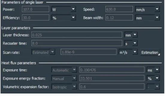
From the SEM image, open source image processing software, ImageJ, was used to determine the particle size distribution and particle roundness of the raw material [91]. A copy of the original SEM image was then inverted and the Gaussian blur image was subtracted to give clear boundary outlines of the particles. For the preparation of the samples in this study, a Coherent Creator™ SLM machine was used with machine specifications as shown by Table 4-4.
The IN718 SLM samples used for the ISM and ND calibration were produced using the parameters provided by ORLAS (the original manufacturer of the Creator™ SLM machine). Displacement measurements of the sheared cantilever specimens were performed with a micrometer at the measurement locations shown in Figure 4-4 (A). This difference in displacement of the cantilevers was accordingly subtracted from the displacement measurements to help refine the specified values for calibration.
SIMULATION METHODS
Mechanical Inherent Strain Method
- Simulation Setup
- Calibration
- Cube Specimens Simulation
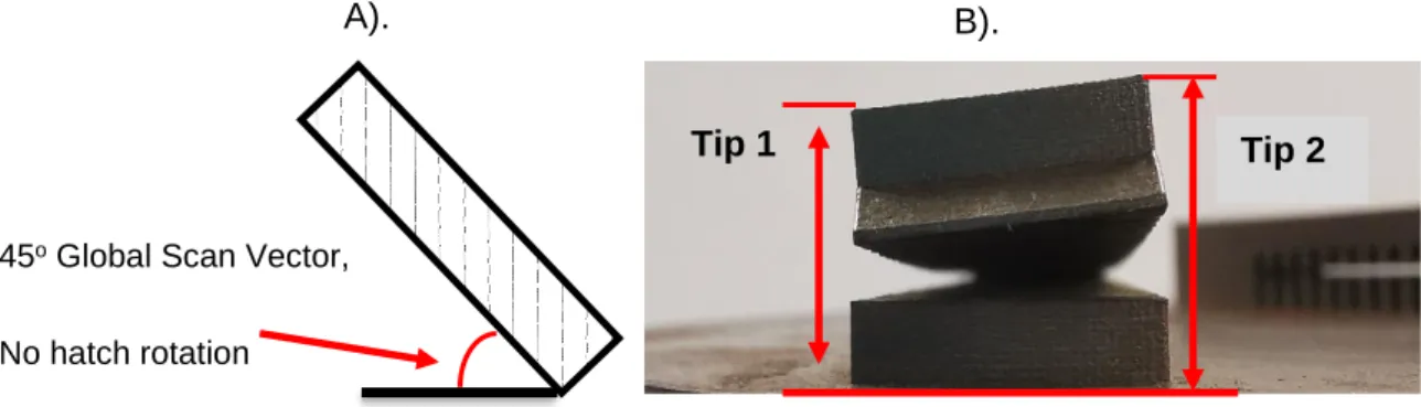
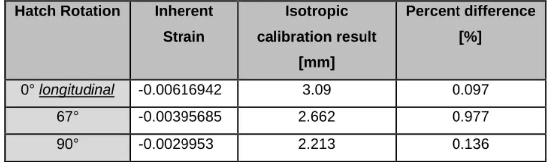
All isotropic simulation calibrations converged to within 1% of the practically measured cantilever displacements, with an increase in displacement corresponding to an increase in the calibrated natural stress value. Using the two 0° HR cantilever displacements as calibration targets, the convergence of the iterative determination of inherent strains is shown in Figure 5-2. To validate the results of the orthotropic calibration, a 45° global scan vector cantilever without rotation of the scan vectors was produced Figure 5-3 (A), with displacement measurements taken at the two locations shown in Figure 5- 3 (B).
The strain validation showed a slight increase in the error of the predicted displacements, increasing from 0.615% to 2.976% between the calibration and validation forces. With calibration of the cantilevers done for both mechanical ISMs, the inherent stress tensors for the elements were saved and used for the simulation of the cubic specimens. The results for the isotropic and orthotropic ISM were analyzed after including removal of the building plate and removal of the support structures in the FEM environment.
Thermomechanical Inherent Strain Method
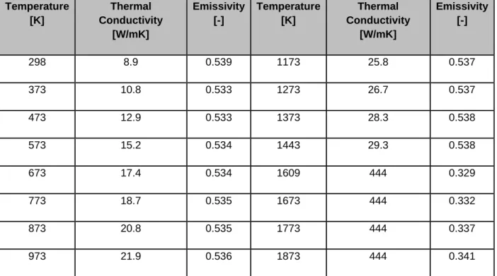
- Material Thermal Properties
- Simulation Setup
- Calibration
- Cube Specimens Simulation
The thermal properties of the building plate and powder material are shown in Appendix A as a function of temperature. After determining the thermal and mechanical properties of the build plate, powder material and solid IN718, the model was further developed with inputs of build and simulation parameters. The calibration iteratively solves for a uniform volumetric expansion factor for the elements based on the thermal history of the cantilever.
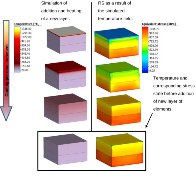
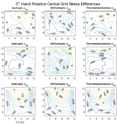
To derive the state of stress of the cubic specimens using the thermomechanical approach, the software solves for the thermal and mechanical state of the specimens by simulating the cycle that occurs with the addition and melting of each layer. This is then coupled to the mechanical FEM to show the state of stress that correlates with the thermal expansion of the newly deposited layer of elements (Figure 5-6). The RS of the cubes after cooling, removal from the build plate and removal of support structure are shown in Figures 5-7 for the central XZ plane of the 0° HR specimen.
Conclusion
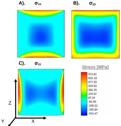
The RS of the cubes after cooling, removal from the build plate, and removal of the support structure is shown in Figure 5-7 for the central XZ plane of the 0° HR specimen. Figure 5-7: ISM thermomechanical stress results for 0° HR with A). The in-plane results at Y = 7.5 mm show large tensile RS in the out-of-plane regions, with compressive RS toward the central regions.
BULK RESIDUAL STRESS MEASUREMENT
- MPISI Specification
- Reference Sample Lattice Spacing
- Neutron Diffraction Measurement Locations
- Bulk Residual Stress Results
- Conclusion
To determine the stress-free grid spacing within the cubes, known as spacing d0, 2. The distribution of central grid measurements for three different HRs is shown in Figure 6-6 for σxx, σyy, and σzz RS. It can also be seen that there were minimal differences in the peak RS of the HR 67° and 90° samples at the central grids for all stress directions.
Where the reference RS is given by the measured RS of the 90° HR specimen at the specific location and the yield is taken as 800[Mpa]. As can be seen, there is quite a bit of difference between the RS values of the 90° and 67° HR specimens as shown by the lower set of contour plots. Further, the effects of HRs on the homogeneity of the RS distribution can be seen at the central measurement positions (Z = 7.5 mm).
![Table 6-1: MPISI machine specifications [82].](https://thumb-ap.123doks.com/thumbv2/pubpdfnet/10395669.0/73.892.196.719.268.945/table-6-1-mpisi-machine-specifications-82.webp)
EFFICACY OF THE INHERENT STRAIN METHOD
Simulation Results Preparation
Comparison of Results
- Central Grid Comparison
- Near Surface Comparison
By determining the maximum and average stress differences, one can see the ability of the simulations to determine the RS in the internal regions of the specimens. Isotropic and thermomechanical approaches were largely ineffective in predicting the RS of the HR-free specimen, with orthotropic ISM being the only viable RS prediction option for this scanning strategy. Again, the orthotropic ISM showed the best fit in determining σxx and σyy, with peak and mean stress differences equal to or smaller than those of the isotropic and thermomechanical ISMs; indicating that the 67° HR stresses are nearly but not completely isotropic in nature.
The percent deviation for the orthotropic simulation types indicated results similar to those for the isotopic simulations, except for the reduced error range for the 0 HR sample (Figure 7-6). Using scan tracks fully perpendicular between layers, as for 90° HR, the isotropic and thermomechanical ISMs were suitable for RS prediction, peak stress differences were all below the order of 150 MPa, with the exception of the σzz stress. 15 mm, the orthotropic ISM was only superior in determining the RSs perpendicular to the scan tracks (σyy), with reduced efficiency of the σxx stress prediction.
Conclusion
CONCLUSION
Conclusion
Nevertheless, it could be concluded that the ISM gave accurate results for the σxx and σyy RS, with the exception of the sample without HR. Research into the RS distribution has shown the greatest tensile stresses near the surfaces of the specimens; High tensile strength RS was observed at values close to the yield strength of the material and was therefore most important to simulate accurately. From this study, the main findings relate to a combination of parameter choice and the ISM that would most accurately represent the resulting RS build.
It was found that using an HR of 90° would yield the least error for each of the ISM simulation types, resulting in the most homogeneous RS distribution for the X and Y directions. Both the isotropic and orthotropic mechanical simulations were well adept at representing the distribution of the RS in samples with 90° HR. The thermomechanical ISM gave slightly more accurate results from the draft RS in regions near the surface, albeit at a much higher computational cost.
Recommendations
Yi et al., “Effect of laser energy density on the microstructure, mechanical properties and deformation of Inconel 718 samples produced by selective laser melting,” vol. Yang, “Interface characterization and mechanical properties of 316L stainless steel/inconel 718 produced by selective laser melting,” Mater. Fullen, “Effect of heat treatment variations on the mechanical properties of Inconel 718 selective laser melted samples,” Addit.
Glatzel, “Microstructure and mechanical properties of selective laser melted Inconel 718 compared to forging and casting,” Mater. Liu, “Effect of standard heat treatment on the microstructure and mechanical properties of selective laser melting fabricated Inconel 718 superalloy,” Mater. Giun, “Effect on microstructural and mechanical properties of Inconel 718 superalloy produced by selective rescanning laser melting at low energy density,” J.
Song et al., "Understanding Processing Parameters Affecting Residual Stress in Selective Laser Melting of Inconel 718 through Numerical Modeling," J. Mumtaz, "Effect of Scanning Strategies on Residual Stress and Mechanical Properties of Selective Laser Melted Ti6Al4V," Mater.
![Figure 2-5: Scanning strategies commonly employed in the SLM process (adapted from [24])](https://thumb-ap.123doks.com/thumbv2/pubpdfnet/10395669.0/25.892.207.692.107.651/figure-scanning-strategies-commonly-employed-slm-process-adapted.webp)
![Figure 3-3: Neutron diffraction difference in path length as a result of crystal lattice spacing (adapted from [78])](https://thumb-ap.123doks.com/thumbv2/pubpdfnet/10395669.0/52.892.194.708.111.308/figure-neutron-diffraction-difference-crystal-lattice-spacing-adapted.webp)