University
of Cape
Town
D E N S E G R A N U L A R F L O W I N R O TAT I N G D R U M S : A C O M P U TAT I O N A L I N V E S T I G AT I O N
O F C O N S T I T U T I V E E Q U AT I O N S t i m o t h y m a r k p ova l l
Thesis presented for the degree of Doctor of Philosophy in the Department of Physics
University of Cape Town April 2018
Supervisors:
Prof. Indresan Govender Dr Andrew McBride Prof. B. Daya Reddy
University
of Cape
The copyright of this thesis vests in the author. No Town
quotation from it or information derived from it is to be published without full acknowledgement of the source.
The thesis is to be used for private study or non- commercial research purposes only.
Published by the University of Cape Town (UCT) in terms
of the non-exclusive license granted to UCT by the author.
Timothy Mark Povall: Dense granular flow in rotating drums: A compu- tational investigation of constitutive equations,© April2018
D E C L A R AT I O N
I know the meaning of plagiarism and declare that all of the work in this thesis, save for that which is properly acknowledged, is my own Vancouver, April2018
Timothy Mark Povall
A B S T R A C T
The constitutive laws of dense granular flow are investigated. Sim- ulations of a drum, with periodic boundary conditions, rotating at varying speeds are performed. From the resulting data, kinematic and kinetic fields are extracted and used to investigate the validity of constitutive relations proposed in the literature (Jop et al.,2006; Path- mathas,2015; da Cruz et al.,2005). Two key constitutive assumptions are (a) isotropy and (b) incompressibility. The rotating drum system is found to be largely isotropic for high rotational speeds. For low ro- tational speeds, anisotropy is observed in the bottom part of the sys- tem, where the particles are flowing upwards. A small degree of com- pressibility is observed in the downward-flowing layer. The friction coefficient for the granular constitutive relations is also investigated.
An empirically-derived friction law has a better fit to the data when compared to other friction laws proposed in the literature. Lastly, two scaling laws are investigated: the scaling between the scaled flow-rate (flux) and the thickness of the downward-flowing layer and the scal- ing between the dynamic angle of repose of the bed and the flux through the downward-flowing layer. The thickness-flux scaling is measured by interpolating the flux over a number of slices through the flowing layer, this is done in a number of different ways. The size of the measured section through the flowing layer is varied. The ori- entation of the slices is also varied. Also investigated is whether the total velocity or the tangential velocity produce the same scaling. The size of the section of the flowing layer significantly changes the scal- ing, this shows that the scaling is not constant throughout the flowing layer. The dynamic angle of repose is determined using two methods, one which is determined unambiguously as the repose angle of the ellipse fitted to the equilibrium surface and the other which is the changing angle of the tangent to the equilibrium surface or free sur- face. The first repose angle is found to be highly dependent on the flux even in the limit of infinite drum length, which is modelled us- ing axial periodic boundary conditions. The second definition results in two sets of repose angles with complex behaviour that may be due to inertial effects. An instability in the system is observed, this is conjectured to be due to a frictional threshold that is breached as the rotational speed of the drum increases. Algorithms for calculating field variables and features of the charge are presented.
iv
namque papaveris haustus itemst facilis quod aquarum;
nec retinentur enim inter se glomeramina quaeque et perculsus item proclive volubilis exstat.
(And you may scoop up poppy seed as easily As water, which will also, if you spill it, Glide away with as ready a downward flow.)
— Lucretius (99-55B.C.), "De Rerum Natura"
(R. C. Trevelyan,1937)
A C K N O W L E D G M E N T S
I am grateful to my supervisors Dr Andrew McBride and Prof. In- dresan Govender for their advice and support. My thanks go to Prof.
Daya Reddy for providing work space at the Centre for Research in Computational and Applied Mechanics as well as my peers in this space for the positive and stimulating work environment. The fund- ing provided by the National Research Foundation and the Centre for Minerals Research is gratefully acknowledged. I greatly appreciate en- couragement from family and friends. My thanks to Keri Povall and Ron Uken for providing a comfortable working space during the final stages of writing. I am appreciative of the advice and interest from my parents, Mark and Julie Povall. Most importantly, I am grateful to my wife Raïssa Philibert for all of her support.
v
C O N T E N T S Notation 1
1 i n t r o d u c t i o n 3 2 l i t e r at u r e r e v i e w 6
2.1 Introduction 6
2.2 Flow in rotating drums and tumbling mills 6 2.3 Kinetic theory 9
2.4 Simulation 11
2.5 Granular rheology 12 2.6 Scaling 17
2.6.1 Flowing-layer thickness 17 2.6.2 Dynamic angle of repose 18 2.6.3 Summary 19
2.7 Summary 20
3 m i c r o-s c a l e m o d e l 21 3.1 Introduction 21
3.2 Discrete element method 21 3.3 Viscoelastic contact law 23 3.4 DEM Simulations 25
3.4.1 Numerical software 25
3.4.2 Rotating drum simulations 26 3.4.3 Settling of the system 27 3.5 Summary 31
4 m e s o-s c a l e c o n s t i t u t i v e l aw 32 4.1 Introduction 32
4.2 Kinematics 32 4.2.1 Motion 32
4.2.2 Velocity gradient 33 4.3 Stress and Balance Relations 33
4.3.1 Body force and traction 33 4.3.2 Stress 34
4.3.3 Momentum balance 34 4.3.4 Mass conservation 34 4.4 Constitutive models 34
4.4.1 Derivation of constitutive models for fluids 35 4.4.2 Bingham and Herschel-Bulkley fluids 36 4.4.3 Dense granular flow model 36
4.5 Summary 37
5 h o m o g e n i z at i o n a n d f e at u r e e x t r a c t i o n 39 5.1 Introduction 39
5.2 Spatio-temporal averaging 39 5.3 Velocity 41
5.4 Stress 41
vi
c o n t e n t s vii
5.5 Velocity gradient 49 5.6 Packing fraction 51
5.7 Approximating the location of the equilibrium- and free surfaces 55
5.7.1 Equilibrium Surface 55 5.7.2 Free surface 59
5.8 Inertial number 59 5.9 Summary 59
6 i n v e s t i g at i o n o f c o n s t i t u t i v e l aw s 63 6.1 Introduction 63
6.2 Compressibility 64 6.3 Coaxiality 64 6.4 Colinearity 73
6.5 Friction coefficient 74 6.6 Packing fraction 77 6.7 Conclusion 78 7 s c a l i n g r e l at i o n s 80
7.1 Introduction 80
7.2 Flowing layer thickness 81 7.3 Dynamic angle of repose 89
7.3.1 Global repose angle 89 7.3.2 Local repose angle 91 7.3.3 Summary 91
7.4 Conclusion 91 8 c o n c l u s i o n 96
a p l o t s t h r o u g h t h e c e n t r e o f c i r c u l at i o n 99 b c oa x i a l i t y p l o t s u s i n g t h e d e v i at o r i c o f t h e s y m-
m e t r i c v e l o c i t y g r a d i e n t 101 b i b l i o g r a p h y 106
L I S T O F F I G U R E S
Figure2.1 Six categories of granular flow in rotating drums. 7 Figure2.2 Regions of flow in a rolling or cascading rotat-
ing drum. 8
Figure2.3 Surfaces and regions in a continuously-flowing mills and rotating drums. 9
Figure2.4 12 rpm angular difference. 15
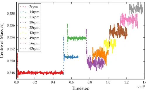
Figure2.5 Time-averaged speed in a drum with lifters. 19 Figure3.1 Diagram for two spherical particles in contact. 23 Figure3.2 The headHhfor all of the simulations. 28 Figure3.3 The departure shoulderHd for all of the simu-
lations. 29
Figure3.4 The height of the centre of mass(Hc)z for all of the simulations. 29
Figure3.5 The height of the centre of mass (Hc)z for the simulation investigating the slipping event. 30 Figure3.6 The average force tangent to the surface of the
drum. 30
Figure4.1 A diagram of a body undergoing a deforma- tion. 34
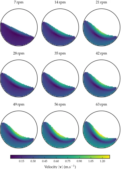
Figure4.2 The effective friction coefficient proposed by Lee et al. and experimental data of GDR MiDi. 38 Figure5.1 A volumetric element with spheres inside. 40 Figure5.2 The magnitude of the velocity|v|over the test
space. 42
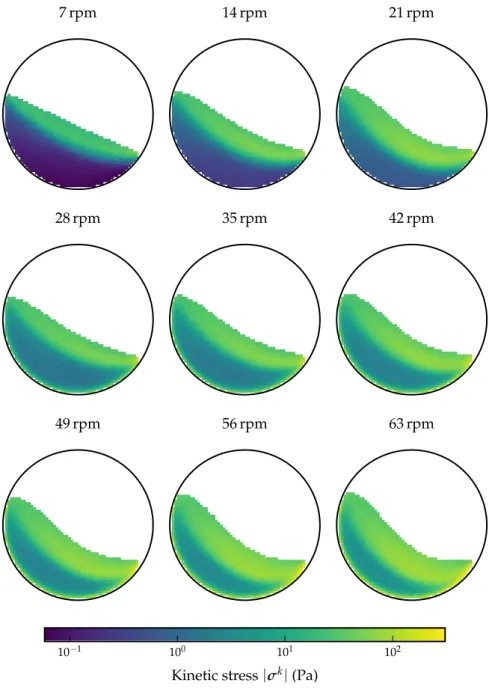
Figure5.3 The magnitude of the kinetic stress |σk| over the test space. 46
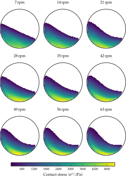
Figure5.4 The magnitude of the contact stress|σc| over the test space. 47
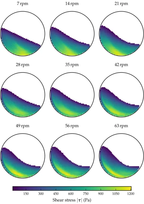
Figure5.5 The magnitude of the shear stress|τ|over the test space. 48
Figure5.6 The pressure pover the test space. 50 Figure5.7 Linear regression forL. 51
Figure5.8 The magnitude of the velocity gradient|L|over the test space. 52
Figure5.9 The standard error for the velocity gradient
|SL|over the test space. 53
Figure5.10 Three cases of a sphere intersecting a periodic volumetric element. 54
Figure5.11 Packing fractionφover the test space. 56 Figure5.12 The triangulation of the63rpm flow field. 57
viii
List of Figures ix
Figure5.13 An illustration of a methodology to find the equilibrium surface. 58
Figure5.14 The speed|v|over the test space, with the equilibrium- and free-surfaces. 60
Figure5.15 Histograms of the inertial numberI. 61 Figure5.16 The inertial numberIover the test space. 62 Figure6.1 The divergence of the velocity ∇ ·v over the
test space. 65
Figure6.2 The ratio|Dvol|/|Ddev|over the test space. 66 Figure6.3 Diagram illustrating the measure of coaxiality
θ. 68
Figure6.4 The measure of coaxialityθover the test space. 69 Figure6.5 Comparison of coaxiality measure. 70
Figure6.6 Frequency comparison of coaxiality measure. 70 Figure6.7 The measure of coaxialityθvs the inertial num-
ber I. 72
Figure6.8 Histograms of the measure of coaxiality θ for every simulation. 72
Figure6.9 The scaling between the principle directions of τandDover the test space. 73
Figure6.10 Frequency of the scaling between the principle directions ofτandDover the test space. 74 Figure6.11 The friction coefficientµ vs the (log-scale) in-
ertial number I. 75
Figure6.12 The friction coefficientµvs the inertial number
I. 75
Figure6.13 The packing fractionφversus the inertial num- ber I. 77
Figure6.14 The packing fractionφ versus the (log-scaled) inertial numberI. 78
Figure7.1 Four scenarios of slices through the flowing layer 82
Figure7.2 20 slices through the flowing layer perpendic- ular to the free-surface. 83
Figure7.3 20 slices through the flowing layer perpendic- ular to the equilibrium-surface. 84
Figure7.4 The scaled flow rate √
Q∗ versus scaled flow- ing layer thickness h/d, relative to free sur- face. 86
Figure7.5 The scaled flow rate √
Q∗ versus scaled flow- ing layer thicknessh/d, relative to equilibrium surface. 86
Figure7.6 The scaled flow ratep
Q∗totversus scaled flow- ing layer thickness h/d, relative to free sur- face. 87
Figure7.7 The scaled flow ratep
Q∗totversus scaled flow- ing layer thicknessh/d, relative to equilibrium surface. 87
Figure7.8 The relationship between drum rotational speed and the value of the exponent of the power- law fit m done for each simulation for all of the scenarios. 89
Figure7.9 Ellipses that are fitted to the equilibrium sur- face for each simulation. 93
Figure7.10 The dimensionless flow rate versus tan(ϕ). 94 Figure7.11 The local repose angle relative to the free sur-
face. 94
Figure7.12 The local repose angle relative to the equilib- rium surface. 95
Figure A.1 The velocity tangent to the normal of the line through the centre of circulation. 99
Figure A.2 The shear rate|γ˙|on the line through the centre of circulation. 99
Figure A.3 The measure of coaxialityθon the line through the centre of circulation. 99
Figure A.4 The pressure p on the line through the centre of circulation. 100
Figure A.5 The inertial number I on the line through the centre of circulation. 100
Figure A.6 The shear stressτxyrelative to the line through the centre of circulation. 100
Figure B.2 Comparison of coaxiality measure usingDdev 101 Figure B.1 The measure of coaxialityθ over the test space
usingDdev. 102
Figure B.3 Frequency comparison of coaxiality measure usingDdev. 103
Figure B.4 The measure of coaxialityθvs the inertial num- ber I usingDdev. 103
Figure B.5 Histograms of the measure of coaxiality θ for every simulation usingDdev. 104
Figure B.6 The scaling between the principle directions of τandDover the test space usingDdev. 104 Figure B.7 Frequency of the scaling between the principle directions ofτandDover the test space using Ddev. 105
x
L I S T O F TA B L E S
Table2.1 An overview of previous works on scaling laws for rotating drums and flow down a heap. 18 Table3.1 The parameters for the two types of materials
in the DEM simulations. 26
Table3.2 Time taken for each simulation, in real and vir- tual time, as well as the number of timesteps. 27 Table7.1 Parameters for power-law best-fit for various
scenarios of slices through the flowing layer. 88
L I S T O F A L G O R I T H M S
Algorithm1 Outline of the procedure for the Discrete Ele- ment Method (DEM). 22
Algorithm2 Algorithm to approximate the equilibrium sur- face. 58
xi
N O TAT I O N
The following is a summary of standard notation adopted.
s c a l a r s, v e c t o r s a n d t e n s o r s
The field variables used in continuum mechanics can be scalar, vector- or tensor-valued. These are generally represented by lower-case, bold lower-case and bold upper-case characters, respectively, e.g.
scalars a,b,ρ,· · · vectors u,χ,· · · tensors (second-order) σ,C,· · ·
Vectors and tensors are also represented in indicial form relative to a fixed Cartesian basisei, i=1, 2, 3, e.g.
u=uiei, C=Cijei⊗ej.
The convention in index notation is that the sum is taken over re- peated subscripts, i.e.
Cijxj =
Ndim
j
∑
=1Cijxj,
where Ndim is the rank (dimension) of the tensor or vector. Tensors are linear transformations of other tensors. A second-order tensor is a linear transformation of a vector (first-order tensor) to another vector, e.g.
Cx =borCijxj =bi. o p e r at i o n s
The trace of a second order tensorT is defined as the sum over the diagonal entries in the tensor:
tr(T) =Tii. (0.1)
The vector dot product is the scalar product between two vectors:
a·b= aibi. (0.2)
The vector cross product is given by
a×b=aibjεijk, (0.3)
1
List of Algorithms 2
where εijkis the Levi-Civita tensor, in 3D given by
εijk =
+1 if(i,j,k)is(1, 2, 3),(2, 3, 1)or (3, 1, 2),
−1 if(i,j,k)is(3, 2, 1),(1, 3, 2)or (2, 1, 3), 0 ifi= j, or j= k, ork= i.
(0.4)
d e r i vat i v e s, g r a d i e n t a n d d i v e r g e n c e
The derivatives of scalar, vector and tensor fields are defined by
∂a
∂x = ∂a
∂xjej,
∂u
∂x = ∂ui
∂xjei⊗ej.
The gradient operator is the derivative of a field relative to the spa- tial (Eulerian) or material (Lagrangian) setting. All of the fields and operators in this work are expressed relative to a spatial setting. The gradient of an arbitrary vector fielduis denoted by
gradu≡ ∂u∂x = ∂ui
∂xjei⊗ej.
The divergence of an arbitrary vector fielduis denoted by div(u) = ∂ui
∂xi.
The divergence of an arbitrary tensor fieldTis denoted by div(T) = ∂Tij
∂xj ei.
1
I N T R O D U C T I O N
A granular system is composed of a collection of particles that range in size from 1µm, e. g. talcum powder, to 1km, e. g. asteroids. The mi- croscopic and macroscopic scales are the scales of, respectively, the unseen (small) and seen (large) parts of a system. The macroscopic scale is generally considered to be many orders of magnitude lar- ger than the microscopic scale. In granular systems the microscopic scale is the scale of the particle. Depending on the size of the particle the micro- and macro-scales can be separated by only a few orders of magnitude. Some granular systems are therefore more accurately defined as mesoscopic systems, which exist in the intermediate scale between microscopic and macroscopic.
Granular systems can have features that resemble solid-, liquid-, and gas-like flow. The phases of flow are characterized by the types of interactions between the particles. In solid-like flows, particles mostly interact via frictional contacts. Gas-like flows have interactions dom- inated by collisional contacts. Liquid-like flows exhibit a combination of frictional and collisional interactions. A dense granular system is composed of dry particles that are mostly in contact with one another.
The particles in a system undergoing rapid dense granular flow are travelling at high velocities, e. g. flows of sand down a dune. How- ever, the velocity of the particles in such systems is not high enough for the particles to be flowing in a predominantly gas-like manner.
The material studied in this thesis is undergoing rapid dense flow and is composed of dry spherical particles.
Comminution is the process of reducing the average size of the particles in a granular system. Tumbling mills are horizontally-oriented drums commonly used in the mining industry for comminution. The particles in a tumbling mill are crushed as it rotates. The mechan- ism of breakage in a tumbling mill is not clearly understood. The two main mechanisms that have been proposed are attrition, a slow wearing-down of the surface of the particles, and fracture (Hogg, 1999). In industry, tumbling mill efficiency is optimized based on em- pirical models. At best the efficiency of tumbling mills (the percentage of energy that is used to break the particles) is around 5% and the en- ergy used in tumbling mills accounts for around 60% of the plant’s operating costs (Wills et al.,2015). A complete mechanistic model of breakage in a tumbling mill does not yet exist. This would be invalu- able as it would allow for rapid prototyping of industrial mills. In this thesis the rotating drum system is studied; this is an idealization of a tumbling mill with dry spherical particles.
3
i n t r o d u c t i o n 4
Key to a mechanistic model of tumbling mills is a constitutive law for granular flow. Constitutive laws are relations between kinematic and kinetic quantities. Jop et al. (2006) proposed a widely-adopted three-dimensional (3D) constitutive law for rapid dense granular flow of dry particles. The constitutive law assumes that the flow has a response that is independent of the orientation at a point, i. e. iso- tropic, and of constant density, i. e. incompressible. The main aim of this thesis is to investigate the validity of Jop et al.’s law by assessing these assumptions. The isotropy assumption is assessed using a novel measure for quantifying the degree of anisotropy in the system. The compressibility assumption is assessed using the spatial gradient of the velocity. In addition, Jop et al.’s proposed form of the viscosity, also called the friction coefficient, is evaluated and compared with the form proposed by da Cruz et al. (2005), and a new empirically- derived form.
The investigations to confirm Jop et al.’s law may be considered an extension of the work of Rycroft et al. (2009) and Cortet et al. (2009).
Rycroft et al. performed 3D Discrete Element Method (DEM) simula- tions of tall and wide silo drainage, as well as a pushing simulation in which half of the domain is moved upwards. All three systems are periodic along one of their axes. Cortet et al. performed 2D DEM sim- ulations of a rotating drum filled with disks. A novel contribution of the work presented here is the use of data from 3D DEM simulations of a rotating drum to investigate Jop et al.’s law.
Scaling laws for granular systems are also investigated. The scaling between the thickness and the flux in the middle of the downwards- flowing layer is key to understanding the dynamics of the system.
Various methods for calculating the thickness-flux scaling are com- pared. Also studied is the scaling between the flux through the flow- ing layer and the angle it makes with the horizontal. This relation has been used to derive a friction law (Pouliquen,1999). Both of the scal- ing laws require knowledge of the location of the equilibrium surface, which is the boundary between upward and downward flow, and the free surface, which is the surface created by the top-most layer of particles in the system. Novel procedures for finding these surfaces are proposed here.
The thesis is arranged as follows. A review of the literature on dense granular flow is given in Chapter 2. An overview of DEM is given in Chapter 3. Chapter 4 focuses on the continuum theory of granular fluids. A derivation of the constitutive law for an isotropic and incompressible fluid is provided and a number of existing con- stitutive laws are outlined. The constitutive law of Jop et al. (2006) is covered in some detail. The homogenization techniques used to ob- tain kinetic and kinematic measures are described in Chapter5. The methods for approximating features of the flow field as well as the packing fraction (volume fraction) of the particles in the system are
i n t r o d u c t i o n 5
also provided. The assumptions of isotropy and incompressibility in the constitutive laws are investigated in Chapter6. The forms of the friction coefficient and the packing fraction are also explored. Scaling laws are investigated in Chapter 7. Conclusions and recommenda- tions are presented in Chapter8.
2
L I T E R AT U R E R E V I E W
2.1 i n t r o d u c t i o n
Ralph Alger Bagnold is considered to be a pioneer of desert explor- ation. During his time in the desert of North Africa in the 1930s he made a number of significant observations which were later included in his bookThe Physics of blown sand and desert dunes(Bagnold,1954b).
His work was the first to propose a constitutive law for a granular fluid based on the kinetic theory of gases. In acknowledgement of the immense contribution of his work towards granular flow and the physics of sand dunes, a field of dunes on the surface of Mars was named after him.
Subsequent work on the kinetic theory of Bagnold has shown that it is only applicable to highly kinetic systems, which mimic gases. The focus of the present work is on rapid-dense flow of granular materials.
These are systems in which the particles flow more slowly than in kinetic systems. This literature review covers the more recent work on rapid-dense granular flow, with a focus on the constitutive laws that have been developed and the work on flow in rotating drums and tumbling mills. Special attention is also given to the scaling laws governing the flows in such systems.
This chapter is arranged as follows. The categorization of flow in rotating drums and tumbling mills is given in Section2.2. Bagnold’s kinetic theory and subsequent work is summarized in Section 2.3. A review of the numerical simulation of granular systems is given in Section2.4. The literature on granular rheology is reviewed in Section 2.5. Scaling laws are discussed in Section2.6.
2.2 f l o w i n r o tat i n g d r u m s a n d t u m b l i n g m i l l s
The flow of granular material in rotating drums is central to this thesis. This section provides background on the flow regimes and features of the flow field. Flows of dry particles in rotating drums ex- hibit all of the features that have been observed in granular systems.
This includes solid-, liquid- and gas-like behaviour. The flow-regimes can be divided into six categories according to rotational speed, as shown in Figure2.1. At low speeds, Figure2.1(a) and (b), the flow is not continuous, with slumping (avalanches) occurring intermittently.
The frequency of slumping is dependent on the rotational speed and the size and diameter of the particles (Mellmann,2001; Henein et al., 1983). The flows of particles during the avalanches are similar to heap
6
2.2 f l o w i n r o tat i n g d r u m s a n d t u m b l i n g m i l l s 7 flows (GDR MiDi,2004; Pont et al.,2003). At higher speeds, Figure2.1 (c) to (f), the downward flow in a rotating drum becomes continuous.
The particles start centrifuging at very high speeds, Figure2.1(f).
(a) Slipping (b) Surging (c) Rolling
(d) Cascading (e) Cataracting (f) Centrifuging Figure2.1: Six categories of granular flow in rotating drums. Schematics
(a) through (f) depict the flow profiles with increasing rotational speed.
The flow in rotating drums is often described by (a) a surface layer (called the free surface) flowing over a densely packed en-masse layer that is considered static relative to the rotating drum; and (b) an in- ternal layer, marking the boundary between rising and falling flow, called the equilibrium surface. Figure 2.2 shows the regions of flow that are typically studied in the rolling, cascading and cataracting re- gimes. These schematics are based on those of the Groupement de Recherche Milieux Divisés (GDR MiDi, 2004). The upward-flow of material is considered to be static (plug flow) relative to the drum.
The downward flow ranges from quasi-static, near the equilibrium- surface, to rapid dense (liquid-like) flow at the free surface. The velo- city in the flowing layer decreases approximately linearly with dis- tance from the free-surface until it reaches the quasi-static region, where it decreases exponentially to zero at the equilibrium surface.
Beyond the equilibrium surface, the velocity increases linearly up to the boundary where it approaches the velocity of the drum. The free flowing layer, the liquid-like linear region just below the free-surface, has particles interacting by frictional and collisional contacts (Pouli- quen et al.,2002; GDR MiDi,2004; Forterre et al.,2008). The bulk de- formations in the quasi-static (exponential) region are slow and the particles interact mostly by frictional contact (Roux et al.,2002). Cas-
2.2 f l o w i n r o tat i n g d r u m s a n d t u m b l i n g m i l l s 8 cading and cataracting regimes will additionally have a highly-kinetic (gas-like) cataracting region above the free surface (Goldhirsch,2003).
The volume of material in the gas-like region increases with rotational speed.
Static flow
Quasi-static flow Equilibrium surface Free-flow
ing layer
y
x
Figure2.2: Regions of flow in a rolling or cascading rotating drum. R is the radius of the drum, the orthonormal coordinate system(x,y) used in some scaling laws is shown in blue. Lastly, the angle of reposeϕis shown.
A rotating drum that is widely used industrially is the tumbling mill, which is used to grind granular media. Metal balls are used to aid the grinding process in certain types of mills. Radially arranged lifters, parallel to the axis of rotation, often line the inside of the drum.
The lifters are intended to increase efficiency of the machine by in- creasing the effective friction on the inside wall of the mill. Tumbling mills are often run at a high speed with cataracting flows, see Figure 2.1(e).
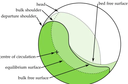
In rapidly-rotating tumbling mills and drums there are a number of scalar features as well as a set of surfaces that divide the bed into regions with distinct granular behaviour in the profile of the flow.
Figure2.3illustrates some of these features:
• The bed free surface is the surface created of the uppermost particles in the bed.
• The bulk free surfaceis the surface below which the particles are constantly in contact.
2.3 k i n e t i c t h e o r y 9
• The departure shoulder is defined as the point at which the rising region leaves the wall of the drum, previously this has been called the shoulder (Powell et al.,2004).
• The bulk shoulder is the point at which the bulk free surface and equilibrium surface intersect.
• Theheadis the highest point on the bed free surface.
• Thecentre of circulationis the only stationary point in the bed.
The region bounded by the bulk and bed free surfaces contains particles that are in free fall, flowing in a gas-like manner with contacts between particles being infrequent and elastic. For slower mill speeds the free- fall region is negligible and the bulk and bed free surfaces will coin- cide.
head bulk shoulder departure shoulder
centre of circulation equilibrium surface
bed free surface
bulk free surface
Figure2.3: Surfaces and regions in a continuously-flowing mills and rotat- ing drums.
As mentioned in Chapter 1, the low efficiency of industrial mills provides a strong need for improving the understanding of granular flows in rotating drums. This need forms part of the motivation for this thesis.
2.3 k i n e t i c t h e o r y
Bagnold’s kinetic theory is not investigated in this thesis; this section is included due to its historical importance. The theory was based upon the results of annular shear cell experiments on a system with particles made of paraffin wax and lead stearate in a fluid of glycerine, water and alcohol (Bagnold, 1954a). For particle inertia-dominated
2.3 k i n e t i c t h e o r y 10 flows, the shear component of the stress, denotedσxyin their coordin- ate system, was found to have a quadratic dependence on the shear rate (velocity gradient) ∂vx
∂y , given by σxy =χ(λ)ρpd2
∂vx
∂y 2
, (2.1)
whereχ(λ)is a function of the inter-particle spacing,ρpis the density of the particles andd is the diameter of the particles.
The kinetic theory assumes that the inter-particle collisions are elastic and that friction between particles is negligible. Ogawa et al. (1980) derived constitutive relations for kinetic granular systems.
The constitutive relations have the same quadratic form as Bagnold’s, which was obtained semi-empirically. Savage et al. (1981) presented a theory of the stress in rapidly shearing granular materials1. Ding et al. (1990) used the kinetic theory of granular flow to derive a model of two-phase flow for a fluidized bed. When compared with data from 2D fluidized bed experiments, the model predicted the time- averaged porosity correctly. Ancey et al. (1999) examined the bulk stress for granular suspensions. In suspensions, the bulk stress has a fluid component in addition to a component arising from the inter- particle forces. They observed a mismatch in bulk and true dissip- ation rates. The bulk dissipation rate is the rate at which energy is dissipated in the bulk and the true dissipation rate is the rate for net energy dissipation for the whole system. Ancey et al. found that the true dissipation rate can only be the same as the bulk dissipation rate if the dissipation rate due to contacting particles is negligible. This observation led them to question the validity of other energy-based computations of the bulk viscosity for suspensions.
Jenkins et al. (2002) proposed a kinetic theory that takes frictional interactions into account. The theory compared well with numerical simulations of a shear cell containing inelastic frictional spheres.
Rajchenbach (2004) emphasized the inapplicability of the Bagnol- dian and kinetic theories to dense flow. It was argued that in dense flows the main means of particle interaction is not elastic collisions, and the transport of momentum is mainly by pressure waves (sound) passing through the network of contacting particles. Lois et al. (2006) tested the binary collision assumption. They show that the formation of multi-contact clusters lead directly to the breakdown of the binary collision assumption.
Bagnold’s kinetic theory, while historically significant, has been shown to be inaccurate for dense flows. The key assumption that the particles are contacting via elastic collisions no longer holds for dense flows with continuously contacting particles. The theory will therefore not be investigated in this thesis.
1 A detailed review of granular flow modelling up to1984was given by Savage (1984).
2.4 s i m u l at i o n 11
2.4 s i m u l at i o n
The simulations done in this thesis model numerically the individual particles of the system. The first mention of a simulation of a granular system was given in Cundall (1971). In a more detailed paper Cundall et al. (1979) described the method of simulating "distinct" contacting particles that interact via a contact law. Originally called the Distinct Element Method by Cundall et al., the method is now also known as the Discrete Element Method (DEM). A number of advances in al- gorithms has enabled DEM simulations to be run in a highly-efficient manner (Bonet et al., 1991). In addition to the algorithmic advances, the rapid increase in computing power has enabled full-scale simula- tions of tumbling mills containing millions of particles (Cleary et al., 2015a; Cleary et al., 2015b). The computing power of Graphic Pro- cessing Units (GPUs) has been used to speed up significantly the DEM simulations of rotating drums (Hromnik,2013).
In rotating drums, the DEM has been found to match experimental results relatively well. Yamane et al. (1998) compared experimental results, obtained using the Magnetic Resonance Imaging (MRI) tech- nique of Nakagawa et al. (1993) with mustard seeds in a rotating drum, with numerical results obtained from DEM simulations. They noted differences in the shape of the free surface. Yang et al. (2003) found good agreement when comparing results from PEPT experi- ments with DEM simulations. They concluded that DEM is an “ef- fective and reliable” technique for studying the microdynamics in a rotating drum. McCarthy et al. (2010) did a quantitative validation of DEM by comparing simulations with an experimental annular shear cell. They observed that very accurate representations of the shape of the particle were needed in the simulations in order to match the ex- perimental measurements exactly. Govender et al. detailed an X-ray technique for tracking a tagged plastic bead in an experimental mill2. The resulting data were compared to DEM simulations by McBride et al. (2004). McBride et al. observed differences in the head and toe regions of flow. The literature mentioned here shows that DEM can be tweaked to match experimental data exactly and accurately models the microdynamics of real particles.
Rycroft et al. (2009) and Cortet et al. (2009) investigated constitutive laws of dense granular flows in, respectively, silo drainage and push- ing simulations and simulations of a 2D rotating drum. In addition, they discussed the limitations and artifices of 2D DEM. More details on these works are given in Section2.5.
DEM simulations of rotating drum systems have been shown to be an effective proxy for the physical systems. An important benefit of numerical systems over physical experiments is the knowledge of the
2 More details can be found in Govender (2005).
2.5 g r a n u l a r r h e o l o g y 12 force between the particles. As a consequence the stress field can be calculated, which is key to understanding constitutive laws.
2.5 g r a n u l a r r h e o l o g y
In this section some context on the development of the 3D constitutive law of Jop et al. is presented. Literature covering the assessment of the constitutive law is also presented. In experiments of granular flows down inclined planes, Pouliquen (1999) found the scaling given by
pu
gh ∝ h
hstop(ϕ), (2.2)
where u andhare the depth-averaged velocity and the height of the flowing layer, respectively. For each experiment, for some value of ϕ, Pouliquen would stop the source of flow and measure the thickness of the flowing layer once it had come to rest. This thickness is expressed as hstop(ϕ) in Equation 2.2. The threshold angle ϕ was taken to be related to a frictional threshold. Pouliquen proposed a friction law using the frictional threshold with a depth-averaged force balance through the flowing layer.
GDR MiDi (2004) suggested that the friction is dependent on the dimensionless rescaled shear rate
I =γd˙ rρp
p , (2.3)
where ˙γis the shear rate andpis the hydrostatic pressure.
The rescaled shear rate I is interpreted as a ratio of two different time scales
I = Tp
Tγ. (2.4)
Consider a layer of particles flowing over another layer, the top layer will be going through a cycle of “climbing” over the particles on the bottom layer and falling back down again. The confinement timescale Tp is the approximate time taken for the top layer to fall back down onto the bottom layer
Tp =d rρp
p . (2.5)
The typical time of deformationTγis the time taken for the top layer to move the distanced over the bottom layer
Tγ = 1
˙
γ. (2.6)
In 2D DEM simulations of disks undergoing shear deformation, da Cruz et al. (2005) confirmed that the state of a granular medium can
2.5 g r a n u l a r r h e o l o g y 13 be determined by I, which they named theinertial number. Small val- ues of the inertial number (I <10−2) correspond to quasi-static flows.
Likewise large values (I >0.2) correspond to the collisional (gaseous) regime. The regime of (liquid-like) dense granular flow corresponds to the middle range of inertial numbers (10−2 < I <0.2). da Cruz et al. (2005) found that both the effective frictionµand the packing frac- tion (solids fraction) φ, which is the proportion of the total volume occupied by the particles, have a linear dependence on the inertial number I given by
φ(I) =φmax−aI, (2.7)
µ(I) =µmin+bI, (2.8)
with constantsφmax'0.81,a'0.3,µmin '0.25 andb'1.1.
Jop et al. (2005) performed experiments of particles flowing down channels of varying width. Like da Cruz et al. (2005) they found that the effective friction µ is dependent on I, but unlike the linear de- pendence of da Cruz et al. (2005) they found the effective friction µ followed the sigmoidal curve
µ(I) =µ1+ µ2−µ1
I0/I+1, (2.9)
with constantsµ1 =tan(20.9°),µ2 =tan(32.76°)andI0=0.279.
Jop et al. (2006) generalized the constitutive law for dense granu- lar flow to three dimensions and used it to perform finite-difference simulations of flow down a channel. The 3D constitutive equation is given by
τ= µ(I) p
|γ˙|Jγ,˙ (2.10)
where the shear rate is given by twice the symmetric velocity gradient as
˙ γ= ∂v
∂x + ∂v
∂x
T
. (2.11)
The norm of the shear rate is non-standard and is given by
|γ˙|J := r1
2γ˙ijγ˙ij. (2.12)
The friction coefficientµ(I) in Equation 2.10 is of the same form as Equation 2.9 and the shear stress tensor τ is the deviatoric (volume preserving) component of the stress tensorσ given by
τ= σ+pI, (2.13)
where I is the second-order identity tensor and the pressure p :=
−1/3trσ. Note here that the usual sign convention for fluid mech- anics is taken where tension is a positive stress and compression a negative stress. Jop et al. redefined the inertial number in 3D as
I =|γ˙|Jd rρp
p . (2.14)
2.5 g r a n u l a r r h e o l o g y 14 Jop et al. found that the velocity at the free surface of chute-flow experiments agreed well with the finite-difference simulations that used the generalized law. Two key assumptions that are necessary for the constitutive law are:
1. The change in the packing fractionφis negligible, which makes the flow incompressible.
2. The shear stressτand shear rate ˙γ tensors are scalar multiples of one another, i. e. colinear.
Forterre et al. (2008) presented a review of current understanding of dense granular flow with focus on constitutive equations. They give the key limitations of the constitutive law of Jop et al. (2006) as:
• The lack of a microscopic explanation of the law.
• The inability of the law to accurately describe flows approach- ing the quasi-static limit.
• Hysteresis effects in the threshold between phases of flow.
• The inability to describe flows approaching the kinetic regime.
A Coulomb material has the same form as Equation2.10, but with constant µ. Schaeffer (1987) showed that a Coulomb material with a von Mises yield criterion (a threshold for the von Mises stress, a multiaxial measure of stress) is ill-posed sometimes in 3D and always in 2D. Barker et al. (2015) showed that in 2D Jop et al.’s rheology is ill-posed for high and low inertial numbers and well-posed for intermediate values. Ill-posed in this case is defined as an instability in numerical solutions. They use numerical error analysis techniques to show that for a given resolution a standard numerical scheme is unstable in the ill-posed parameter space. Based on the findings of Schaeffer (1987), Barker et al. (2015) also suggest, but do not prove, that in 3D Jop et al.’s rheology is likely to be better posed, but “zones of ill-posedness” are still expected.
Lagrée et al. (2011) used a numerical Navier-Stokes solver with Jop et al.’s rheology to solve 2D granular collapse problems. The numer- ical results were found to agree with with analytical and DEM results.
Staron et al. (2012) used the numerical solver of Lagrée et al. (2011) to simulate 2D silo drainage. They showed that the numerical solver could be used to capture the phenomenon of a low-pressure cavity forming at the opening of the silo. Barker et al. (2015) observed that the results of Lagrée et al. (2011) and Staron et al. (2012) may not display the expected zones of ill-posedness due to the ad-hoc regular- izations introduced into the numerical solver to avoid the singularity at low strain rates.
Cortet et al. (2009) performed 2D DEM simulations of slowly ro- tating drums filled with disks. They investigated the assumption of
2.5 g r a n u l a r r h e o l o g y 15 colinearity between the shear stress τ and the deviatoric (volume preserving) part of the shear rate ˙γ tensors for the constitutive law of Jop et al. (2006). These quantities were obtained by splitting the domain into a number of bins and averaging over the particles in- side each bin. The quantities in each element were averaged over400 evenly spaced temporal “snapshots”, which together constituted a single rotation of the drum. In order for the colinearity condition to be satisfied, the principle directions of τ and ˙γ need to be aligned.
They found that the angular difference in alignment betweenτ and
˙
γ ranged from −10° to 10° in the flowing layer, which flows more rapidly (5×10⁻⁴ < I < 5×10⁻²). In the quasi static region below the flowing layer (with 10−6 < I < 5×10⁻⁴) the misalignment in- creased to 35°. Figure 2.4 shows the angular difference between τ and ˙γthroughout the drum. The misalignment is attributed to “tran- sient dilatancy effects” in the slowly deforming regions of the drum.
They also investigated the effective friction µ(I) of Jop et al. (2006).
Despite the misalignment between τ and ˙γ, the scalar effective fric- tion µ = |τ|/p agrees reasonably well with the Jop et al. rheology, even in regions where the inertial number is very small (I ∼ 10−5) and the misalignment is quite large.
Figure2.4: Angular difference between the principle directions of τ and ˙γ for a drum rotating at12rpm. Obtained from Cortet et al. (2009).
Rycroft et al. (2009) performed 3D DEM simulations of particles draining out of tall and wide silos. They also performed a push- ing simulation, where half of the domain was forced upwards, on the wide silo. They investigated the applicability of continuum de- scriptions of flow in spatial (Eulerian) and material (Lagrangian) set- tings. In both cases continuum measures are taken by averaging over rectangular volumetric elements. The Eulerian elements were static, while the Lagrangian elements moved at the mean velocity of the particles therein. Like Cortet et al. (2009), they studied the alignment between the principle directions of the deviator of the shear rate and
2.5 g r a n u l a r r h e o l o g y 16 the shear stress tensors. They found that the average misalignment, over a single snapshot, between the tensors was 12°. If the quantit- ies were averaged over a “window” of 20 temporal snapshots the average misalignment decreased to 6.7°. They also found a linear relationship between the packing fraction φ and inertial number I (φ(I) =0.635−8.13I), which agreed with the results of da Cruz et al.
(2005)3.
Pignatel et al. (2012) performed quasi-2D experiments of rotating drums and found a disagreement between the measured effective fric- tion and that predicted by the constitutive equation of Jop et al. (2006).
The discrepancy was attributed to the influence from the side-walls of the rotating drum.
Hatano (2007) performed DEM simulation of two periodic sheared systems of different sizes. It was shown that the dilatancy φ has a power-law dependence on the inertial number
φ(I) =a−bIc, (2.15)
with constants b ≈ 0.11 and c = 0.56±0.02. a was estimated by extrapolation.
Lee et al. (2012) used the dilatancy law of Hatano (2007) to develop a constitutive model that accounts for hysteresis in the transition from quasi-static to rapid-dense flows.
An empirically-derived exponential law for the packing fraction, based on PEPT experiments, was proposed by Pathmathas (2015).
PEPT is a technique to track a particle tagged with a radioactive tracer (Parker et al.,1993). The proposed law is given by
φ(I) =I0e−bIc. (2.16) The validation of the constitutive law of Jop et al. is a central goal in this thesis. The applicability of the law is bounded at low iner- tial numbers by the hysteresis in the phase transition from liquid- to solid-like flows. At high inertial numbers, the law is unable to capture highly kinetic flows. The rapidly rotating drum system simulated in this thesis has flows with a wide range of inertial numbers, vary- ing from quasi-static to rapid-dense; this allows for a comprehensive assessment of the law. The assumptions of incompressibility and iso- tropy are key to the law. While the DEM simulations of Rycroft et al.
(2009) and Cortet et al. (2009) allowed for an investigation of these assumptions for 3D silo drainage and 2D rotating drum systems; this has not yet been done for 3D simulations of a rotating drum. This thesis is intended to address this gap in the literature.
3 An excellent review of the recent progress of work on rheology of dense granular flow is given in Jop (2015).
2.6 s c a l i n g 17
2.6 s c a l i n g
Scaling laws relate non-dimensional quantities in a system. They are important as they provide constraints to the possible form of a con- stitutive law. The µ(I) friction law described in the previous section is a key scaling relation for determining the constitutive form for the shear stressτ. The literature covering two scaling laws that are invest- igated in this thesis is outlined in this section.
2.6.1 Flowing-layer thickness
The relationship between the velocity and thickness in a layer of flow- ing granular material is a key scaling for understanding the dynam- ical behaviour of the system. When investigating the flowing layer in heap flow and rotating drums, a coordinate system perpendicular to the flowing layer is typically used, shown in Figure 2.2. The fol- lowing assumptions are generally made about the flow in a rotating drum when formulating scaling relations: (a) there is a constant angle of repose of the bed, (b) the flow is not cascading or cataracting, (c) the thickness of the flowing layer (h) is small relative to the radius of the drum, i.e. h2 R2, and (d) the rising region has flux per unit length of drum defined by Qr = ω2 R2−h2 ≈ ω2R2, where ω is the angular velocity of the drum. In addition, some studies on ro- tating drum systems that are very narrow along the axis of rotation make the assumption that the side walls have no influence on the scaling relation.
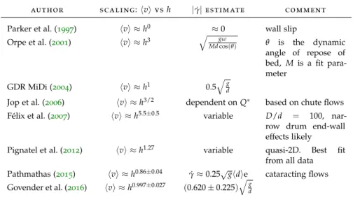
Parker et al. (1997) observed in a series of PEPT experiments of a rotating drum that the flowing layer is roughly two-thirds as thick as the static layer, regardless of speed. Orpe et al. (2001) carried out experiments on a variety of different particles in a thin rotating drum.
Their results showed that the average of the component of velocity tangential to the flowing layer is proportional to the cube of the flow- ing layer thickness, i.e. hvi ∝ h3. In experiments of flows down a rough inclined channel, Ancey (2002) emphasized that the velocity profiles measured at the side-walls are strongly disturbed. Ancey de- scribed two different flow-regimes that are dependent on the Froude number Fr. Above some critical value ofFr the flow has a linear velo- city profile. Below this, a convex velocity profile with a constant mean velocity was observed. The heap flow and rotating drum experiments of GDR MiDi (2004) indicated a linear scaling, i.e.hvi∝ h1. From ex- periments on flow down a chute, Jop et al. (2006) also concluded that there is a linear scaling, and that the distance between the side-walls affects the thickness of the flowing layer.
Félix et al. (2007) ran experiments with various drum and particle sizes. They found the scaling exponent n, where hvi ∝ hn, to be de- pendent on the ratio of drum radius to particle size. The scaling expo-
2.6 s c a l i n g 18
au t h o r s c a l i n g:hviv sh |γ˙|e s t i m at e c o m m e n t Parker et al. (1997) hvi ≈h0 ≈0 wall slip
Orpe et al. (2001) hvi ≈h3 qMdgωcos(θ) θ is the dynamic angle of repose of bed, M is a fit para- meter
GDR MiDi (2004) hvi ≈h1 0.5qgd
Jop et al. (2006) hvi ≈h3/2 dependent onQ∗ based on chute flows Félix et al. (2007) hvi ≈h5.5±0.5 variable D/d = 100, nar-
row drum end-wall effects likely Pignatel et al. (2012) hvi ≈h1.27 variable quasi-2D. Best fit
from all data Pathmathas (2015) hvi ≈h0.86±0.04 γ˙≈0.25√ghdie cataracting flows Govender et al. (2016) hvi ≈h0.997±0.027 (0.620±0.225)qgd
Table2.1: An overview of previous works on scaling laws for rotating drums and flow down a heap.
nent nwas found to range from 5 to 0.5 corresponding to small and large size-ratios, respectively. Pignatel et al. (2012) found that
h
d ≈2.86 hvih dp
dg
!0.44
, (2.17)
where the dimensionless flow rateQ∗ := hvih
d√gd. Rearranging Equation 2.17 gives hvi ≈ h1.27. In addition Pignatel et al. concluded that the side-walls affect the flowing layer thickness.
Govender et al. (2016) performed PEPT experiments on rotating drums with and without lifter bars. They found an approximately linear scaling (hvi∝h0.997±0.027) from measurements of multiple slices through the flowing layer for both cases. Table 2.1 summarizes key information of works done on scaling laws.
2.6.2 Dynamic angle of repose
Another scaling relation investigated in the literature is the relation- ship between the angular speedωand the dynamic angle of reposeϕ.
The dynamic angle of repose is the angle that the free surface makes with the horizontal (see Figure 2.2). Rajchenbach (1990) found the scaling to be ϕ ∝ ω2. Dury et al. (1998) performed a number of ex- periments and simulations of rotating drums. The experiments were performed using MRI with mustard seeds as particles. They found a linear scaling, i.e. ϕ ∝ ω. GDR MiDi (2004) found that the degree of dependence ofϕon the flux, which is proportional to the speed, was inversely proportional to the axial-width of the drum. A very wide drum was found to have an almost constant repose and a narrow drum a strong dependence on the flux.
2.6 s c a l i n g 19 At high speeds the free surface has a curved shape, which makes the repose angle difficult to define uniquely. Govender et al. (2016) proposed redefining the dynamic angle of repose as the angle between the horizontal and the semi-major axis of the ellipse that best fits the equilibrium surface. This definition provides an unambiguous way of finding the repose even for cataracting flows. A flow field with the fitted ellipse is shown in Figure 2.5. To fit the ellipse they used the algorithm of Fitzgibbon (1998).
Figure2.5: Time-averaged speed, obtained with PEPT, of 5mm beads in a 300mm drum with lifters rotating at 15.4 revolutions per minute (rpm). The black squares show the equilibrium surface. A fitted ellipse with the dynamic angle of reposeθe is shown. Obtained from Govender et al. (2016).
2.6.3 Summary
In addition to the assessing the constitutive law of Jop et al.; this thesis is intended to supplement the above-mentioned literature with an as- sessment of the scaling laws over a wide range of flow-regimes. There is little agreement in the literature on the scaling relation between the thickness of a granular layer flowing down a slope and the flux. The most promising seems to be a linear scaling relation, as it has been found in a number of separate studies. In the scaling between the dynamic angle of repose and the flux in the rising layer GDR MiDi (2004) found that the degree of dependence of the repose angle on the flux was inversely proportional to the axial width of the drum. The simulations done in this thesis model a drum that is periodic along the axis of rotation; this will provide data on the limiting case of GDR MiDi’s scaling law, an infinitely long drum.
2.7 s u m m a r y 20
2.7 s u m m a r y
In the continuously-flowing regimes the rotating drum system can contain regions of flow ranging from quasi-static (solid-like) to highly kinetic (liquid- and gas-like) flows. DEM simulations are of great value as, unlike other experimental methods, they allow kinetic quant- ities such as the force between particles and the stress to be calculated over the entire flow-field. To date there has been no assessment of the constitutive law of Jop et al. (2006) using 3D DEM simulations of rapidly-rotating drums, a central aim of this thesis is to provide this assessment. In addition, the wide range of simulation speeds in this work will provide new insight into the velocity-thickness and repose- angle scaling laws.
From an industrial perspective, the design of efficient industrial mills would require rapid prototyping. The prototyping would need to be done using simulations. If Jop et al.’s constitutive law is accurate, the simulations may be done using a fluid model and finite-element or finite-difference methods. The influence of liquid in an industrial mill may mean a similar study on suspensions is needed first, how- ever. Interestingly, some granular suspension literature also make the assumption of isotropy and incompressibility for the constitutive law (Boyer et al.,2011; Trulsson et al.,2012). The results of the assessment of these assumptions in this work may imply that assumptions for granular suspensions also need to be questioned in a similar manner.
3
M I C R O - S C A L E M O D E L
3.1 i n t r o d u c t i o n
Emergent phenomena are those complex phenomena that arise out of a collection of smaller, simpler, entities. The phenomena observed in granular materials, such as hysteresis and segregation, are examples of emergence. It is from the relatively simple interactions between particles at the microscopic scale that these phenomena, at the meso- scopic scale, arise. The mesoscopic scale is the intermediate scale between the micro- and macro-scales. The 3D rotating drum simu- lations that are analyzed in this thesis are performed using the Dis- crete Element Method (DEM), which uses a model of these simple interactions at the micro scale. These simulations are the focus of this chapter.
An overview of this chapter is as follows. An outline of the DEM, based on an explicit time-integration scheme, is given in Section 3.2 A detailed derivation of a model of contact that takes into account the history of contact is given in Section3.3. Details on the hardware, software and configuration of the simulations of a rotating drum that are performed for this work are given in Section3.4.
3.2 d i s c r e t e e l e m e n t m e t h o d
The simulations in this thesis are performed with the DEM. As pre- viously mentioned, the DEM is a numerical method used to model systems of particles in contact with one another. It was originally developed by Cundall (1971) for the analysis of rock mechanics prob- lems. Consider a system ofNparticles, the total forceFi on a particle ican be expressed as the sum of the forces applied by the particles it is in contact with, i.e.
Fi =
Nc
α
∑
=1Fα+mig, ti = Iiαi, (3.1) where Fα is the force applied by contact α, g is acceleration due to gravity and mi, ti, Ii, αi and Nc are, respectively, the mass, torque applied, moment of inertia tensor, angular acceleration and number of contacts for particle i. The contact law, to calculate the force, is described in Section3.3. After dividing the equation on the left bymi the system becomes
Fi
mi =ai =
Nc
α
∑
=1Fα
mi +g, ti = Iiαi, (3.2)
21
3.2 d i s c r e t e e l e m e n t m e t h o d 22 whereai is the linear acceleration of particlei. Finite-difference meth- ods (e. g. forward-Euler, backward-Euler etc.) can be used to approx- imate the solution to the above system of equations.
A forward-Euler approximation is explicit and conditionally stable.
The critical value of the timestep∆tis related to the minimum eigen- period of the system (Chareyre et al., 2005). In systems with large numbers of particles the minimum eigenperiod is difficult to calcu- late. The critical timestep is approximated by considering the speed of pressure waves that propagate throughout the system (Yade Authors, 2016). For a system of spheres the approximated critical timestep is given as
∆tcr =min
i Ri sρpi
Eiy, (3.3)
where Eyi is the Young’s modulus of particle i. A timestep of ∆t = 0.3∆tcrshould be used to guarantee stability (Yade Authors,2016).
The algorithm using the aforementioned approximations for simu- lating a system of particles is summarized in Algorithm1.
Algorithm 1 Outline of the procedure for the Discrete Element Method (DEM).
1. Start with a set of particlesi∈[1,· · ·,N]with some initial positionXi, linear velocityviand angular velocityωi.
2. Step through time with a time-step∆tsatisfying the constraint given in Equa- tion3.3. At each timestep the following is done:
a) The particles that are in contact with one another are determined.
b) The forces between particles in contact are determined. This can be made up of frictional and elastic components, and may depend on the history of the contact. More detail on the contact law is given in Section 3.3.
c) Newton’s second law is used to obtain the linear and angular accelera- tion of each particle from the forces.
d) The displacements and linear and angular velocities of all of the particles are updated.
The contact detection step in Algorithm1is relatively computation- ally expensive, however it is not necessary at every time-step. Contact detection can be skipped if it is known that no new contacts have been made. The rate of change of contacts can be approximated by the speed of all the particles. Faster particles will change contacts more rapidly and contact detection will have to occur more frequently when compared to slow-moving particles.