VICTORIAN INSTITUTE OF ENGINEERS
PAPER
DESIGNING A CONCRETE MIXTURE.
By J. Gilchrist Lang.
It is my intention in presenting this paper to place before you the results of my investigations extending over several years. This paper was prepared for presentation some nice months ago. I have endeavoured to bring it un to date with the later experience I have had on the subject with the limited time at my disposal.
It has been the practice in the past for architects and engineers to specify concrete somewhat in the following manner:—
Concrete to be composed as follows:- 4 parts in. bluestone screenings.
2 parts clean sharp sand.
1 part cement.
The materials are to be measured in a gauge box and be mixed on a clean wooden platform. The concrete to be turned over once dry and twice wet before being deposited in position.
It would appear from the foregoing that there were three materials of importance in concrete, and one, i.e., water, of a very secondary nature that may be used apparently at the discretion of "Joe," the foreman labourer. That this is entirely wrong I will endeavour to prove to you as this paper proceeds.
Architects may to some extent be pardoned for this some- what lax method of specifying in the past as City of Mel- bourne Building By-laws No. 168, part 9, section 37 reads as follows:—
"All cement shall be Portland cement in accordance with the British Engineering Standard Com- mittee's specifications. Aggregate shall be com- posed of clean, sharp, coarse sand and approved gravel, bluestone or other recognised material of
suitable coarseness."
and section 39, sub-section 2:
"The quantity of cement shall be determined by weight and ninety-three pounds shall be deemed to be equivalent to one cubic foot. The ingre- dients of the concrete shall be so thoroughly
a s 7 o e
mixed that the cement shall be uniformly distri- buted throughout the mass and that the resulting concrete shall be homogeneous. Concrete shall be composed of one part cement and not more than two parts sand and four parts gravel or bluestone of gauge not exceeding three-quarters of an inch."
The only reference to the all important water is found in section 39, sub-section 3, where it states:
"If in a plastic state the ramming shall be continued till at least water appears on the surface."
Suburban by-laws are even more vague in this respect.
With these few preliminary remarks I will now take each of the four constituents in turn and briefly describe the vari- ous points that require consideration before they are finally united to form the finished product.
Cement
It would be quite possible to devote the rest of the even- ing to a description of this product, but as the manufacture of same has now reached such a high state of perfection I will confine myself to only a brief outline of same and a few suggestions regarding its use. As is generally known Port- land cement is manufactured by combining limestone (cal- cium carbonate) and shale (silicate of alumina) in predeter- mined proportions, clinkering same to a temperature of 2000-
2500 degrees Fahrenheit, adding a certain proportion of gyp- sum, generally about 22 per cent. to regulate the setting time, then grinding same so that 90 per cent. will pass through a screen .32,400 meshes to the square inch. The material is then bagged, and I might point out in this con- nection that I have found that the variation in the weight of dozens of bags picked at random never exceeds i per cent.
There are two classes of bags on the market at present—one brand in one foot cubic bags weighing 94 lbs., and several other brands. in 1.33 cubic feet bags weighing 125 lbs.
As mentioned before, the cement is generally of high class, but I make it a practice of always specifying on works of importance that the contractors are to allow in their ten- der a sum for testing purposes. This sum is expended from time to time as is found necessary. The cement is required to be in accordance with the British standard for Portland cement, and should any fail to meet the requirements of same It is of course rejected, and the cost of any tests carried out on same has to be borne by the contractors.
Coarse Aggregate.
It has long been the custom to make the cement which forms, generally, but 15 to 25 per cent. of the volume of con- crete meet the most exacting specifications. In the same way aggregate which forms 75 to 85 per cent. should also be tested, and in this direction the American Society for Testing Materials in 3923 drew up the following tentative specification for coarse aggregate:-
"Coarse aggregate shall consist of crushed stone, gravel or other approved inert materials with similar characteristics or a combination thereof, having clean, hard, strong, durable uncoated pieces free from injurious amounts of soft, friable, thin, elongated, or laminated pieces, alkali, or- ganic or other deleterious matter. The following table indicated desirable grading in percentages for coarse aggregate for certain maximum sizes."
°> ,,1 tl ~v tà
g
í. . 'd+v •oou~ M Square Openings. Inch. ~ ó ó ~.ó
~ ~za ~ze
~óH
3 21 2 11 1
b0 ó~~ ó
—~tl WGc
3~ 95 40-75 15 5
22 95 15 5
2 95 40-75 15 5
1i 95 40-75 15 5
I 95 40-75 35 5
4 95 15 5
The fact that the size and gradirigs of the aggregate bear an important relation to the workability and strength of con- crete should not be lost sight of, and in this direction inves- tigations carried out by the American Materials Research Laboratory have shown that the size and grading are the proper bases for proportioning aggregates in concrete.
A measure known as the "Fineness Modulus" has been developed. This measure is the sum of the percentages in the sieve analysis divided by 300, when the sieve analysis is expressed in percentages coarser than the following square mesh sieves.
Sieve No. or Size 100 50 30 16 8 4 it 12
Clear. Opening
In . ... .. .0059 .0118 .0236 .047 .094 .188 .375 0.75 1.5
A few trial calculations will show that the fineness modu- lus becomes greater as the aggregate becomes coarser, and also that the same fineness modulus may be obtained from an
infinite number of sieve analysis. Tests have shown that aggregates having the same fineness modulus require equal amounts of mixing water for a given plasticity, and conse- quently will produce concrete of the same strength so long as other conditions are equal and the aggregate is not too coarse for the quantity of cement used. The relation be- tween fineness modulus and consistencies of concrete is shown graphically in Fig. 3a, b, c, d. It will be seen from these graphs that the greater the slump for a given strength and maximum size of aggregate the higher the fineness mo- dulus and the smaller the real mix of mixed aggregates to each volume of cement.
We will take an example for which we will assume that a 2000 lb. concrete is required, and the maximum size of ag- gregate is to be q- in.
With a slump of z in. to i in. the real mix is 1:6.4 and fineness modulus 5.6.
With a slump of 3 in. to 4 in real mix is 1:5.6 and fine- ness modulus 5.7.
With a slump of 6 in. to 7 in. real mix is 1:4.4 and fine- ness modulus 5.8.
With a slump of 8 in. to i o in. a real mix of 1:3.1 and fineness modulus 5.9.
I will later on in this paper refer again to these graphs.
The accurate determination of the fineness modulus is a matter of great importance, and on work of any magnitude should be accurately determined from time to time to secure the most satisfactory and economical results.
We in Melbourne use practically no other coarse aggre- gate than crushed bluestone. The fineness modulus of this material varies greatly according to the quarry it is procured from. Some of the quarries in screening the crushed stone leave all materials between the 4 in. mesh and 1 in. mesh as one product, i.e., in. screenings, while others divide be- tween these two screens into two sizes, which are marketed as in. screenings and z in. screenings. The first method gives a better graded material, and when it can be procured is preferable. An alternative not to be recommended is the delivery of half in. screenings and half in. screenings, as unless very strict supervision of , the deliveries and subse- quent mixing of same is made, it will be found that part of the time practically all one or other of the two grades will be used, with a result that very uneven strength will be obtained.
is
Other factors to be looked for in the coarse aggregate which are detrimental to the finished concrete are as follows:
(a) The presence of more than a very small percentage of dust in the screenings.
(b) The texture of the stone, care to be taken to re- ject screenings containing more than a small per- centage of honeycomb stone.
(c) The presence of salamander (a brown rotten rock) or clay from the overburden.
The two materials already dealt with, and the part they play in the finished product, are generally fairly well under- stood, but the sand and water have not until very recently received anything like the attention they deserve. Of these the water is by far the most important, and I will therefore deal with that first. I have already pointed out that this has been neglected by architects and municipal authorities
Water:
I will now quote extracts from several well-known text books showing how until recently the authors of same were also very vague on this all important question. Trautwine, 1920, states:—
"Wet concrete is more easily mixed with thorough- ness, more readily and more cheaply laid, and more easily forced into the narrow spaces be- tween reinforcing bars. It comes into more per- fect contact with the moulds, thus giving
smoother surfaces. It is therefore generally preferable (as in buildings) in forms of compli- cated shape, or in thin sections, or where smooth surfaces are required."
Kidder's Architects' Builders' Pocket Book, 1916, states:
"The materials should be mixed wet enough to result in a concrete of such consistency that it will flow into the forms and about the metal reinforce- ment when used, and which at the same time can be conveyed from the mixer to the forms without separation of the coarse aggregate from the mor-
tar." •
An extract from Faber and Design, 1921, reads as follows:
"Considerable difference perts as to how wet results."
Bowie's Reinforced Concrete of opinion exists among ex- a concrete should be for. best
"Tests of laboratory specimens, in which the con- crete can be rammed very hard, show that a dry concrete gi\ es the best results. In practical re- inforced concrete work this cannot be done, since generally the centring will not sustain the neces- sary pressure. For this reason the laboratory tests referred to are of little value, and there is no reason to suppose that a dry concrete is stronger than a wet one when not rammed."
"In practical work it is necessary for the concrete to be of such a consistency that every crevice will be filled. To secure this there is no doubt that a fairly wet concrete is best. As this also gives a good face and makes a dense and waterproof concrete the author considers it best."
"The limit on the wet side is reached when the cement comes to the surface and runs away."
These authors further state.
"It is a mistake to speak of ramming concrete of the best consistency for reinforced work, since it should be too wet to ram and should give way before the tool."
Urquhart and O'Rourke, in "Design of Concrete Struc- tures,' 1923, state:
"Practically all tests have shown that the strength of concrete depends upon the amount of cement used in the mix."
"Reinforced Concrete Design," by G. P. Manning, 1926, makes no mention of the amount of water to be used.
Hool and Johnson, in their 'Concrete Engineers' Hand Book, 1918, state:
"Unfortunately little is known at the present time as to the propor proportions of water."
Stephens and Adamson, 1927, state:
"The amount of water used depends largely upon the character of the work to be done. Ordinarily the concrete should be brought to a jelly-like con- sistency so that it will readily flow to all parts of the form. If too much water is used, the ma- terials tend to separate and the cement comes to the top or the water runs out through the forms carrying cement with it. A `dry mixture' sets more quickly, but will not develop the strength of a reasonably `wet mix.' "
From the extracts it will be noted that the use of water has long been a more or less haphazard process, endured for
want of knowledge of the most important part it plays in the ultimate strength of the concrete. Investigations carried out under the direction of Prof. Duff Abrams, of the Lewis Institute, Chicago, proved beyond the shadow of a doubt that the strength of concrete depends upon the ratio between the volume of the mixing water and the volume of the cement, known as the water-cement ratio. These investigations covered a period of several years, in the course of which over 100,000 tests were made.
The results of these tests have been plotted, and are shown in Fig. 1. Curve A is of concrete where the field oper- ations are under control, and the lower Curve B indicates the minimum strength to be expected when the operations are not under control. It will be seen that they give strengths varying by approximately 500 lbs. per square inch.
It will be seen from the curves that the lower the cement- water ratio the greater will be the strength as long as the mixture is workable. When it is recognised that the addi- tion of one pint more water than necessary in a one bag batch decreases the strength as much as if three pounds of cement had been omitted, one begins to wonder how many of the structures erected in the past are still standing. Let us take just one example using Curve A. If we put io gallons of water to one bag of 125 lbs. of cement, which gives a water-cement ratio of 1.2, we will obtain under rigid control a compressive strength in 28 days of approximately 1¢00 lbs.
If we had only added 6.6 gallons to a batch similar in all other directions we would obtain a compressive strength of 300o lbs., or over loo per cent. greater strength.
I think I have given enough emphasis to the fact that to design a concrete of predetermined strength water, which in the past has only been treated as a minor consideration, is in view of later investigations in conjunction with the cement, of supreme importance.
Sand:
The last product we have to use is the sand. Now the class of sand to be used must be first examined to see it has the following important characteristics: durability, clean- ness, and grading. As the whole of the sands being mar- keted at the present time in Melbourne are of a durable na- ture I will, not take up your time in elaborating on same, and I will deal later on with the grading. We now come to the cleanness of the sand. It has been proved by numerous tests that the presence of organic impurities in sand have a direct bearing on the ultimate compressive strength. Now a very simple method has been evolved for testing for organic impurities. The whole of the apparatus necessary to carry
out these tests is four or five clean medicine bottles graduated in ounces and a stock solution composed by mixing a oz. of sodium hydroxide in 32 ozs. of water. The test is carried out in the following manner:—
Fill one of the bottles to the 4 oz. mark with the sand to be tested. Add the sodium . hydroxide solution until the vol- ume of sand and solution after shaking amounts to 7 ozs.
Shake thoroughly and allow to stand. An approximate idea of the quality may be obtained by observing the colour of the liquid above the sand in a few hours, but the most accurate results are obtained after the solution has been standing for
24 hours.
If the solution is colourless or has only a slight yellow tinge, the sand may be considered satisfactory. I will call these Nos. a and 2. If on the other hand the solution is coloured to approximately the colour of tea, which we will call No. 3, or darker approaching the colour of coffee, which we will call No. 4, the sand should be rejected. It is not possible to give exact values the different colours will reduce the strength of the concrete, but tests carried out on 1:3 mortar at 28 days show the following reduction can be ex- pected:-
No. I, none.
No. 2, Io to 15 per cent.
No. 3, 15 to 30 per cent.
No. 4, 30 to 75 per cent.
As the colourimetric test furnishes a simple and inexpen- sive method of detecting the presence of impurities, everyone who is connected with the supervision of concrete work should make it a principle of constantly carrying out same. It has been the author's experience that frequently sands that ap- pear to be clean are coated with organic impurities of a na- ture that will seriously affect the strength of the concrete.
The next point to be taken -into consideration is the amount of water in the sand, which for two reasons is of great importance. In the first case it must be determined so that allowance can be made for it in arriving at the amount of water that is to be added to preserve the correct water- cement ratio, and secondly the presence of water in the sand has a marked bulking effect.
These characteristics in the sand are not generally under- stood, but it is essential that notice be taken of them. The sand as received in the field contains practically in every in- stance a percentage of moisture which makes the accurate and consistent measuring impossible without special means being employed to compensate for same. Tests carried out
lü
34
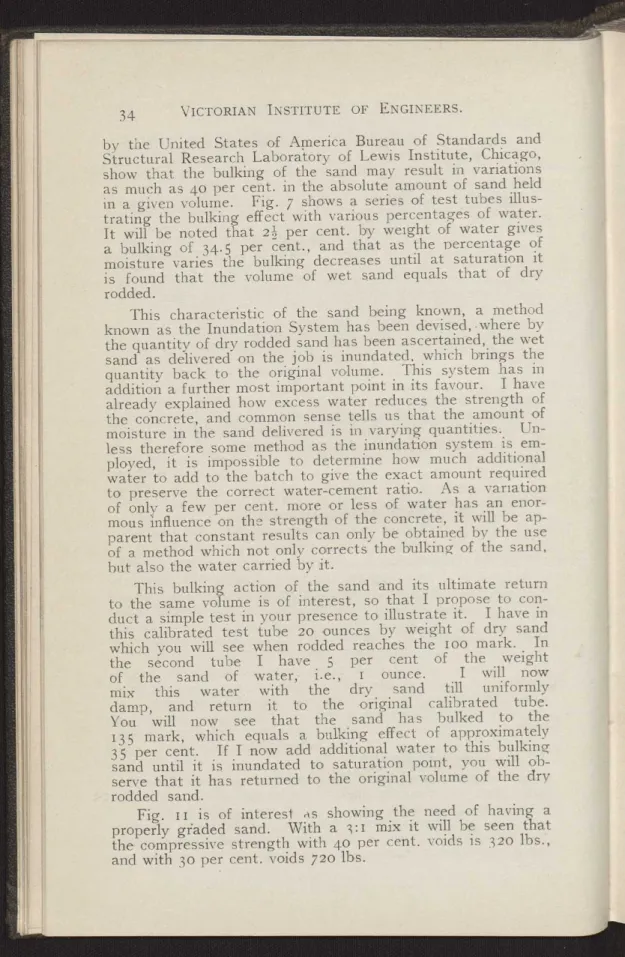
by the United States of America Bureau of Standards and Structural Research Laboratory of Lewis Institute, Chicago, show that the bulking of the sand may result in variations as much as 4o per cent. in the absolute amount of sand held in a given volume. Fig. 7 shows a series of test tubes illus- trating the bulking effect with various percentages of water.
It will be noted that 22 per cent. by weight of water gives a bulking of 34.5 per cent., and that as the percentage of moisture varies the bulking decreases until at saturation it is found that the volume of wet sand equals that of dry rodded.
This characteristic of the sand being known, a method known as the Inundation System has been devised, -where by the quantity of dry rodded sand has been ascertained, the wet sand as delivered on the job is inundated, which brings the quantity back to the original volume. This system has in addition a further most important point in its favour. I have already explained how excess water reduces the strength of the concrete, and common sense tells us that the amount of moisture in the sand delivered is in varying quantities. Un- less therefore some method as the inundation system is em- ployed, it is impossible to determine how much additional water to add to the batch to give the exact amount required to preserve the correct water-cement ratio_ As a variation of only a few per cent. more or less of water has an enor- mous influence on the strength of the concrete, it will be ap- parent that constant results can only be obtained by the use of a method which not only corrects the bulking of the sand, but also the water carried by it.
This bulking action of the sand and its ultimate return to the same volume is of interest, so that I propose to con- duct a simple test in your presence to illustrate it. I have in this calibrated test tube 20 ounces by weight of dry sand which you will see when rodded reaches the roo mark. In the second tube I have 5 per cent of the weight of the sand of water,- i.e., i ounce. I will now mix this water with the dry sand till uniformly damp, and return it to the original calibrated tube.
You will now see that the sand has bulked to the 135 mark, which equals a bulking effect of approximately 35 per cent. If I now add additional water to this bulking sand until it is inundated to saturation point, you will ob- serve that it has returned to the original volume of the dry rodded sand.
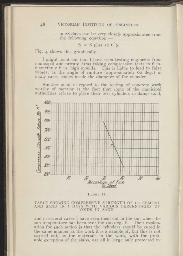
Fig. II is of interest as showing the need of having a properly graded sand. With a 3:I mix it will be seen that the compressive strength with 40 per cent. voids is 32o lbs., and with 3o per cent. voids 720 lbs.
portions of cement and aggregates to produce concrete of which as has been pointed out gives the desired strength at the least cost.
terials, I will now proceed with the steps to be taken in de- sign of a concrete mixture. This resolves itself into the pro- the desired workability with a given water-cement ratio,
Having described the characteristics of the various ma-
I will divide the necessary steps into i 5 sections as fol- lows:-
(i) Fix upon the strength of the concrete required.
(2) Determine the water-cement ratio required from Fig. i.
(3) Determine the degree of workability required.
(4) Procure average samples of the aggregate it is proposed to use.
(5) Make tests as previously described to determine the cleanness and quality.
(6) Determine the moisture content of aggregates.
(7) Make sieve analysis of aggregate to determine their fineness modulus and maximum sizes.
(8) Determine the real mix and the fineness modulus of such a mix from Fig. 3.
Calculate the percentages of the fine and coarse (9)
aggregate to produce the required fineness mo- dulus of mixed aggregate.
(I o) Determine the unit weights of fine and coarse aggregate, in the condition in which they will he delivered for use on the job.
(i i) Determine the ratio of the volume of the mixed aggregate to the sum of the separate volumes measured dry and rodded.
(12) Calculate the nominal mix.
(is) Calculate the field mix.
(i¢) Determine the quantities of materials per cubic yard of finished concrete from Fig. 6.
(i5) Calculate the amount of water to be added to the batch.
This may appear to be a long and tedious process, but to illustrate to you that such is not the case I propose to take an example and go through the design.
Section i .—We will assume that the concrete is to be used in the construction of a reinforced concrete building, and that a compressive strength of 2000 lbs. per square inch will be required to be developed in 28 days. As we may
meet with reinforcing bars near the surface, we will need a fairly plastic concrete, which we will take as that repre- sented by a slump of 6 in.
Section 2.: Water Ratio: The water cement ratio can be read directly from Fig. 1. In this case we will use Curve B, assuming that rigid control will not be exercised throughout the job. We find that the ratio required is 0.90, which is equivalent to 5.62 gallons of water to one cubic foot cement, or 7.5 gallons to 125 lbs. bag.
Section 3.—Workability: 6 in. slump to be used.
Section 4.---Samples of Aggregate: A representative sample of say 40 lbs. of sand and 8o lbs. of coarse aggregate should be carefully selected. To select a fair average sample from the before-mentioned amounts the following method should be employed:—
Place the samples on a clean floor or other convenient place, and mix thoroughly with a trowel, spread- ing the material out in a circle to a thickness of about 3 in. Divide this sample into quarters, and discard two opposite quarters, remix the two left and repeat the operation till a sample of the. re- quired size is obtained.
Section 5.—Cleanness and Quality: Carry out tests as previously described to discover any impurities.
Section 6.—Moisture Content: Dry a given weight of each aggregate and note the loss of weight which is naturally the moisture content. We will assume for this example that the moisture content of the sand is 3 per cent. by weight, and the stone 2 per cent.
Section 7.—Sieve Analysis and Fineness. Modulus: Take about 2 lbs. of sand and 20 lbs. of coarse aggregate which have been obtained by quartering a large sample as pre- viously described, and thoroughly dry same. Sieve all sizes to point of practical refusal. Obtain the weight of the total amounts coarser than each sieve and express them as per- centages (by weight) of the total sample. Add these per- centages and divide the sum by 100. This sum is the fine- ness modulus. We will assume that the sieve analyses were as follows:—
Per cent. coarser than each sieve. 0 s a).b bo N
0'm
Agg' gate 100 50 30 16 8 4 1 1 11 5 o m a Sand .. 85 70 55 25 15 0 0 0 0 2.50 0-4 Stone .. 100 100 100 100 100 100 70 30 0 7.00 4-11
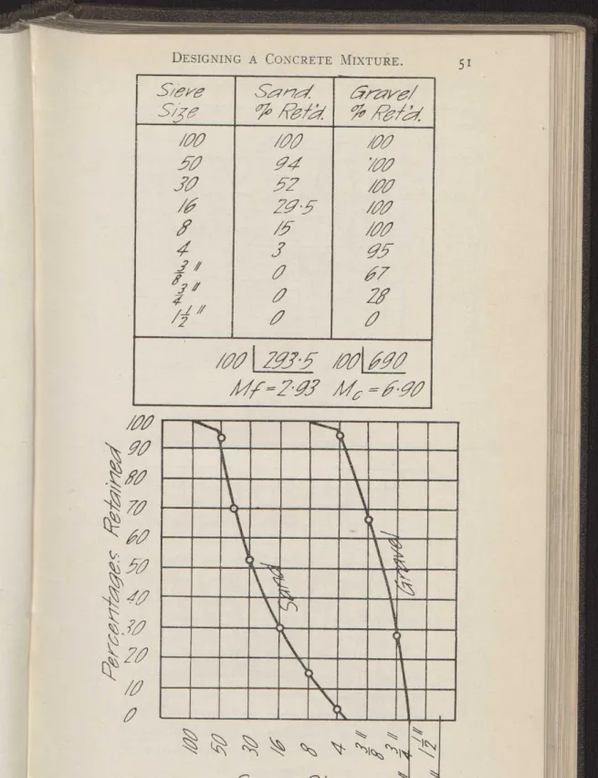
An alternative method of carrying out a sieve analysis is to have only a half set of sieves, i.e., Nos. 5o, i6, 4, in.
When the analysis has been made with these sieves the per- centages may be plotted on ruled paper as shown in Fig. 2, and the values of the intermediate sizes obtained by drawing a sweet curve through the plotted points. The fineness mo- dulus should then be calculated as for a full set of sieves.
The results obtained form a sufficiently accurate guide for practical working operations.
Size Classification.—The size to be assigned to a given aggregate is determined by the following rules:--
I. At least 15 per cent. shall be retained on the sieve next smaller than that considered the maximum size. Thus a graded sand with 15 per cent. or more retained on the No. 8 sieve would be classi- fied in the 0-No. 4 size; if 14 per cent. or less were retained on the No. 8 sieve the sand would fall in the 0-No. 8 size. A coarse aggregate having 15 per cent. coarser than the 2-inch sieve would be considered as 3-inch aggregate.
2. Not more than 15 per cent. of a given aggregate shall be finer than the sieve considering the mini- mum size.
In this example we find that range in size of sand to be 0 to No. 4 and stone graded from No. 4 to Li in.
Section 8. From curve for a slump of 6 in. Fig 3C finds the point of intersection of 2000 lbs. per square inch curve with the maximum size of aggregate curve, i.e., g in. Pro- ceed to the left, and we find that a real mix of 1:4.4 is indi- cated. From the same intersection of these two curves drop vertically to the bottom, where we find that the required fine- ness modulus of the mixed aggregate will require to be 5.8.
Section g.—As we have determined the fineness modulus of the sand as 2.5 and the stone as 7.00, and the fineness mo- dulus of the mixed aggregates as 5.8, we have now to deter- mine what proportions of sand and stone are required to give us same. This is found by the equation—
Mc – M r
–
Mc – Mf
When M = fineness modulus of mixed aggregate.
Mf = fineness modulus of fine aggregate.
Mc = fineness modulus of coarse aggregate.
r = ratio of volume of fine aggregate to sum of the volume of fine and coarse aggregates measured separately.
(I – r) = ratio, of coarse aggregate.
1íl
38
In our example this is, as follows:- 7.0 – 5.8
r = – 0.27
7.0 – 2.5
In other words, 27 per cent. of the total volume of separate aggregates is sand, 73 per cent. is stone.
Section io.—Unit Weight of Fine, Coarse and Mixed Ag- gregates: Find the weights per cubic foot of the aggregates damp and loose, duplicating as closely as possible the condi- tions that will occur when they are used on the job; next dry the samples and the weights of sand, stone and mixed aggre- gates. (In the proportions calculated to produce the fineness modulus of 5.8.)
In our example we find unit weights as follows:—
Sand damp and loose .. .. .. . .. .. go lbs. cub. foot go lbs. sand as above when dry .. 87 lbs. cub. foot Sand dry and rodded .. .. .. 108 lbs. cub. foot Stone damp and:loose .. .. .. Ioo lbs. cub. foot Combined aggregates dry and rodded in
the proportions of 27 Der cent. sand
and 73 per cent. of stone .. .. .. .. 123 lbs. cub. foot You will now understand the importance of basing calcu- lations on materials in a standardised condition, i.e., dry and rodded, in view of my previous remarks relative to the bulk- ing of the sand and the moisture contained therein.
Coarse aggregates do not bulk to any appreciable extent when damp, but when rodded may weigh as much as 10 per cent. more than when measured loose.
Section I1.—Ratio of Volume, of Mixed Aggregates to Sum of Separate Volumes: This is calculated from the follow- ing equation:—
Let y = ratio of volume of mixed aggregates to sum of volumes of separate aggregates.
r = ratio of volume of sand to sum of volume of separate aggregates.
Wf = Unit weight of fine aggregate (sand).
We = Unit weight of coarse aggregate (stone).
Wm = Unit weight of mixed aggregate.
rWf plus (I – r) We
Then y = Wm
Substituting the values shown under Section 1o, we have ratio of mixed to separate aggregates =
(0.27 x 1o8) plus (I – 0.27) 105 123.
This means that combining 0.27 cub. feet of sand and 0.73
cub. feet of stone we only get a mixed aggregate of o.86 cub. feet.
We use this ratio of shrinkage, as I believe contractors call it, in computing the nominal mix from the real mix.
It follows that owing to this foot of the real mix volume Section I2.—Nominal Mix:
shrinkage that for each cubic
1.00
—cubic feet of aggregates 0.86
required.
measured separately will be
In our example we find the real mix to be 4.40, this 4.40
means that -- or 5.12 cubic feet of aggregates measured 0.86
separately must be used.
27 per cent. of this is sand = 1.38 cub. feet.
73 per cent. of this is stone = 3.74 cub. feet.
The nominal mix is therefore—
I:1.38:3.74 based on dry rodded material.
If the inundation system was used our problem would now be completed, but I will describe an alternative method Before doing so, however, I will just transgress for a few moments here to briefly describe the measuring of the sand by the "Inundator."
To eliminate adjustments to the sand hatcher and wate tank to compensate for bulking and water content, the "sand inundator" was invented. This is based on the principle tha sand when completely inundated has the same volume as when dry, and it replaces the sand batcher in the hatcher plant.
Its essential parts are a sand-measuring container with adjustable bottom, a water charging tank, an excess water ank, a shaker and a sand shifter and a strike off gate. The and container is adjustable to contain the volume required f dry sand. The total amount of water per batch is calcu- ated as before, assuming dry sand. The water charge is et to contain the amount of water required to inundate the and—a fixed quantity so long as the same sand is used and qual to the voids in the sand-and the excess water tank is et to hold the difference between this amount and the total mount required.
The operation is as follows:—The main line water valve is opened' filling the charging tank, the overflow passing through an overflow pipe to the excess water tank, and when this tank begins to overflow the valve is shut off. The two a
•
r t
t s 0
1
s s e s
40
tanks then hold exactly the required amount of water for the batch. The valve controlling the water charger is then opened, allowing the water to drain into the inundator or sand container, and the operator sifts the sand into the con- tainer by means of the shaker gate. This is to give com- plete inundation. If there is any excess water in the inun- dator above that required for inundation it escapes at the overflow.
When the inundator is full of sand the level is struck off, a latch is released, and the sand and water automatically dump into the mixer. The excess water tank valve is then opened, and this water discharges directly into the mixer.
The whole operation takes less than 45 seconds, which is less than the time required for mixing.
Section 13.--Field Mix: The nominal mix we have deter- mined is, as I have mentioned, based on dry rodded m'aterial.
On the job we have to deal with damp materials measured loose. The effect of bulking and loose measurement must be taken into consideration.
We have already found that i cubic foot = go lbs. of damp loose sand (87 lbs. when dry) is equivalent in volume to 108 lbs. of dry rodded sand.
It will therefore require 87 = 1.24 cubic feet of damp I08 bulked sand for every cubic foot of dry rodded sand in the nominal mix. In other words, the nominal mix of 1.38 cubic feet will become 1.38 x 1.24 = 1.71 in the field mix.
A similar comparison of dry rodded material in its damp state shows that - 105 98 = 1.07 cubic feet of damp loose stone ror each cubic foot of nominal mix. That is the nominal mix of 3.74 becomes 3.74 x 1.07 = 4.00 in the field mix. Our field mix therefore becomes—
I:1.71:4.00
Section 14.—Quantities of Material Required per Cubic Yard of Finished Concrete: A very close approximation of the amount of cement required can be obtained from Fig. 6.
In our example for the real mix of 1:4.4 we find that ap- proximately 5.8 sacks of i cubic foot or 4.6 sacks of 125 lbs.
or 1.3 cubic feet are required.
If we were using a mixer capable of taking one cubic foot bag of cement our final field mix will be for each cubic yard of finished concrete-
Sand-5.8 x 1.71 = 9.92 cub. feet = 0.37 cub. yards.
Stone-5.8 x 4.00 = 23.2o cub. feet = o.86 cub. yards.
Section I5.--Water-Cement Ratio: The quantity of mix- ing water to be added to preserve the water-cement ratio of 0.90 is determined as follows:—
From Fig. I we find that 5.62 imperial gallons are required for each cubic foot sack of cement. From this we have to subtract that water already contained in the aggregate.
This can be obtained by actual experiment, but should there be only a small quantity of concrete to be poured certain ap- proximations are generally sufficiently accurate.
Experiments show that in sand this is seldom less than 2 per cent., and usually between 2 per cent. and 4 per cent.
except when it is raining, when up to 8 per cent. moisture should be allowed for. In normal weather 4 per cent. is a safe percentage to use. Likewise the stone should be tested.
We will assume in our example that 3 per cent. of mois- ture by weight is present in the sand and 2 per cent. in the stone.
The deduction necessary from the 5.62 imperial gallons is therefore
I.71 x go x 0.03 = 4.62 lbs.
4.00 x Ioo x 0.02 = 8.00 lbs.
Total .. 12.62 lbs. = 1.3 gals.
The quantity of water for each cubic foot sack is there- f ore-
5.62 - I.25 = 4.37 gallons.
or 25.35 gallons to each cubic yard.
Our complete field mix for i cubic yard finished concrete is therefore-
5.8 cub. feet cement.
0.37 cub. yds. sand.
o.86 cub. yds. stone.
25.35 gallons of water.
The principles I have just described may be applied in the solution of varied problems that arise in concrete construc- tion. Following are a few typical examples:—
(a) To obtain the same strength of concrete by the use of fine or coarse sand.
(b) To determine the strength that will be obtained when the mix, aggregate and consistency are fixed.
(c) To determine the mix that will give the highest strength with given aggregates, slump and quan- tity of cement per cubic yard of concrete.
MIXING.—Now that we have our mixture, attention should be given to the time same is in the mixer and the speed the mixer is run. Fig. 8 shows a series of tests carried out and Aver a*
5000 /ósa-o "
Jam
/OM a
h
3000y xra
h Z000 ZO00
MOO /NO
10
7
SH-
/110
d d
Zlìd
1.)..16789/0.//2 i«IA7/~9 fine in /Uinuks.
f /0 /S ZO ZZ f0
R PAL //Amt.
Figure 8.
EFFECT OF TIME OF MIXING AND SPEED OF MIXER ON STRENGTH.
included in a report issued by the Joint Committee of Stand- ard Specifications for Concrete and Reinforced Concrete issued in 1921.
It will be noted that the strength rapidly increases dur- ing the first two minutes; concrete mixed for two minutes is of 25 per cent. to 35 per cent. greater strength than concrete mixed for only a quarter of a minute. Concrete should be mixed for a minimum period of two minutes, and preferably three minutes. Thorough mixing in addition gives increased plasticity, which, as gentlemen present are aware, saves many stoppages when same is being conveyed by chutes.
Speeding up the mixer has little effect on the strength of the concrete, as will be seen from the lower diagram. It is time of mixing and not the speed of the mixer that insures strength.
It will be found on most average constructional jobs that a mixture taking two one cubiç foot bags of cement is a most convenient size, and will give all the output that can be con- veniently handled.
In conclusion, the quesfion that naturally arises in your minds is "What benefits are to be derived from controlling the manufacture both by design and field control?"
I will admit that the years of experience of 1:2:4 concrete roughly measured and mixed with as much water as Joe in charge of the mixer thinks fit, or is directed by Dick and Tom,. his colleagues, who are placing the mixture in position, to put more ! water in so that their task may be easier cannot be discarded in a day, but it is only when architects, engineers and contractors realise the advantages and take the initiative that we will secure the use of concrete that is advantageous to everyone concerned.
Engineers and architects with "Field Control" will be able to design for any strength desired and be sure of getting it consistently. They can use higher stresses, and in this con- nection I feel confident that in the future with "Field Control"
the maximum extreme fibre stress of 600 lbs. per square inch for a 1:2:4 concrete at present allowed by the Melbourne City Council will be increased. Concrete as manufactured in the old haphazard way frequently fell to i600 ibis. per square inch at 28 days, giving a safety factor of 2.66 which is still safe. Now if we can guarantee a strength of 2000 it would be perfectly feasible to use a stress in design of 75o to Soo lbs. per square inch, and this is still conservative.
Contractors before they invest in new plant and changed methods must be shown a monetary gain.
A small outlay in plant and a study of the methods of de- sign I have placed before you will place contractors in a position where they are ahead of their competitors both in unit costs of the concrete and the added feeling of confidence they must naturally feel in the knowledge that they are turn- ing out the best possible work.
Accurate cost sheets have been kept on a large number of jobs carried out under "Field Control" methods in U.S.A.
and Europe, and the savings have been considerable. A few of these savings. are as follows:—
(a) A saving of up to 10 per cent. of cement.
(b) Even consistency saving time in blocked chutes.
(c) No segregation—labour saved in working the con- crete in forms and true surfaces obtained saving labour in cleaning off and rubbing down.
That such a system is not only necessary for the safety, but also for economical construction, is shown by tests car- ried out by the Testing Department of the Melbourne City Council. The following is_ an extract from June number of
"Commonwealth Engineer":—
"In the first case a sample was taken which at 28 days showed a compressive strength of 1720 lbs. per
44
square inch. A second sample was taken four weeks later, and this at 28 days gave a result of 3200 1A. per square inch. Another sample taken four weeks later than the second gave a strength of 3660 lbs. after 28 days. A specified strength of concrete at 28 days is 2400 lbs. In the second case the sample showed 790 lbs. per square inch after 28 days. Another sample taken a few days later gave a strength of z3oo lbs. per square inch. In the third case three. tests at intervals resulted as follows:—I, 814 lbs.; 2, 2920 lbs.; 3, 3680 lbs. These figures speak for themselves
,
but until consistent and adequate re- sults are obtained there will always be a danger of failure."Compared with the above cases I would draw your atten- tion to a job recently completed in Swanston-street with
"Field Control." A 2000 lb. concrete was specified, and as a result of numerous tests on each floor the following 28 day strengths were obtained:—
Ground .. 2083 lbs. per square inch.
First .. .. 1993 lbs. per square inch.
Second .. .. 2102 lbs. per square inch.
Third .. .. 2086 lbs. per square inch.
Roof .. .. .. 2440 lbs. per square inch.
Job Average 2141 lbs. per square inch.
I mentioned previously the saving that is effected by cor- rect proportioning, and in this direction I would like to give you an example of a job carried out under the supervision of a committee of American Concrete Institute at the end of 1926.
The specified strength was 2000 lbs. per square inch at 28 days. The available aggregates were sand graded from in. to dust and gravel from 1 in. to 4 in. It was found that by properly designing the mix concrete with a slump of 3 to 4 inches could be used in lieu of the wetter mix giving a 6 to 7 inch slump usually used. The results were as fol- lows:—
Cost per Cement. Sand. Gravel. c. vd.
3 in. to 4 in. slump 439 lbs. 0.42 c. yds. 0.69 c. yds. 19/- 6 in. to 7 in. slump 546 lbs. 0.36 c. yds. 0.72 c. yds. 21/8
According to the report of the committee no extra labour costs were entailed.
The same repcct gives tables comparing a 1:2:4 concrete with a strength of 2000 lbs. at 28 days. The extra cost of the 1:2:4 mix ranged from I/22 to 2/52 per cubic yard..
The tests were carried out on a small job of 1494 cubic yards of concrete, and the saving effected was -174/6/-.
This saving is based on American rates; local conditions and prices would considerably increase same.
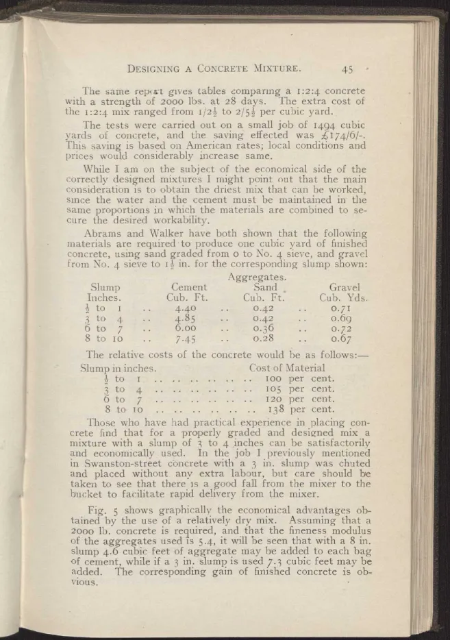
While I am on the subject of the economical side of the correctly designed mixtures I might point out that the main consideration is to obtain the driest mix that can be worked, since the water and the cement must be maintained in the same proportions in which the materials are combined to se- cure the desired workability.
Abrams and Walker have both shown that the following materials are required - to produce one cubic yard of finished concrete, using sand graded from o to No. 4 sieve, and gravel from No. 4 sieve to 12 in. for the corresponding slump shown:
Aggregates.
Slump Cement Sand Gravel
Inches. Cub. Ft. Cub. Ft' Cub. Yds.
2 to 1 4.40 .. 0.42 ... 0.71
3 to 4 4.8 5 0.42 o.6g
6 to 7 6.00 .. 0.36 0.72
8 to 10 7.45 0.28 0.67
The relative costs of the concrete would be as follows:—
Slump in inches. Cost of Material
to I Too per cent.
3 to 4 105 per cent.
6 to 7 .. .. .. . 120 per cent.
8 to 10 138 per cent.
Those who have had practical experience in placing con- crete find that for a properly graded and designed mix a mixture with a slump of 3 to 4 inches can be satisfactorily and economically used. In the job I previously mentioned in Swanston-street còncrete with a 3 in. slump was chuted and placed without any extra labour, but care should be taken to see that there is a good fall from the mixer to the bucket to facilitate rapid delivery from the mixer.
Fig. 5 shows graphically the economical advantages ob- tained by the use of a relatively dry mix. Assuming that a 200o lb. concrete is required, and that the fineness modulus of the aggregates used is 5.4, it will be seen that with a 8 in.
slump 4.6 cubic feet of aggregate may be added to each bag of cement, while if a 3 in. slump is used 7.3 cubic feet may be added. The corresponding gain of finished concrete is ob- vious.
G
01
You will I am sure agree with me that the economical re- sults obtained warrant the attention required to achieve this result.
The importance that is attached to scientific proportion- ing in England may be gauged from the fact that the fourth year engineering students at the English Universities are now required to include the design of concrete mixes for specific strengths as part of their regular course. In America night classes have been formed, and the engineers and foremen of contracting firms attend same to familiarise themselves with this important subject. It would be of undoubted benefit to not only the contractors in Victoria but engineers and archi- tects as well if such a course were adopted here.
Before closing I would like to just briefly describe the me- thods employed in carrying out various tests of the concrete being used.
SLUMP TEST.—A simple method of testing the consistency of the concrete mixtures and making slight regulations in the amount of water to be added is by the slump test. The only apparatus necessary is a slump cone, which can be purchased from any tinsmith for a few shillings. This truncated cone is I2 in. high, having a top diameter of 4 in. and a bottom diameter of 8 in.
The slump is taken as follows:—The cone is placed on a smooth surface and filled with a representative sample in layers of 4 in., rodding each layer 3o times with a ft in. dia- meter pointed steel rod. Lift the cone off gently after the last layer has been rodded and the top levelled off, and meas- ure the amount of settlement of the concrete in inches.
COMPRESSION TESTS.—As a record for future reference on every job of any, magnitude a complete series of compressive tests should be carried out.
The taking of samples for testing purposes should be in the hands of an experienced man, and the following standard method can be recommended:—
(a) The moulds are constructed as shown on Fig. Io, and should be made of some non-absorbent ma- terial.
(b) In securing samples the concrete shall be taken from the mass by a shovel and placed in a bucket for transport to point of moulding. Before plac- ing in test moulds the concrete shall be stirred up to offset segregation, and then be placed in 4 in, layers in the moulds, each layer being rodded 3o times with a ft in. diameter pointed steel rod 24 in.
long. When the mould is full the top layer shall be struck off level with a trowel and a non-ab- sorbent plate placed over same. After a period
; "x 3"Sqa,are head ba/f z 'X /4 "See/ pi,de.
`T6 ii Sfrap /rori Ifb/%%
' :r 3'~sgziare head bo/f See/ p~e.
S`ieef /ror. Ro/%d
Figure 10.
MOULDS FOR COMPRESSION TEST CYLINDERS.
of about four hours a thin layer of stiff neat ce- ment should be spread over the top and worked true in order that the cylinders may preserve a smooth end for testing.
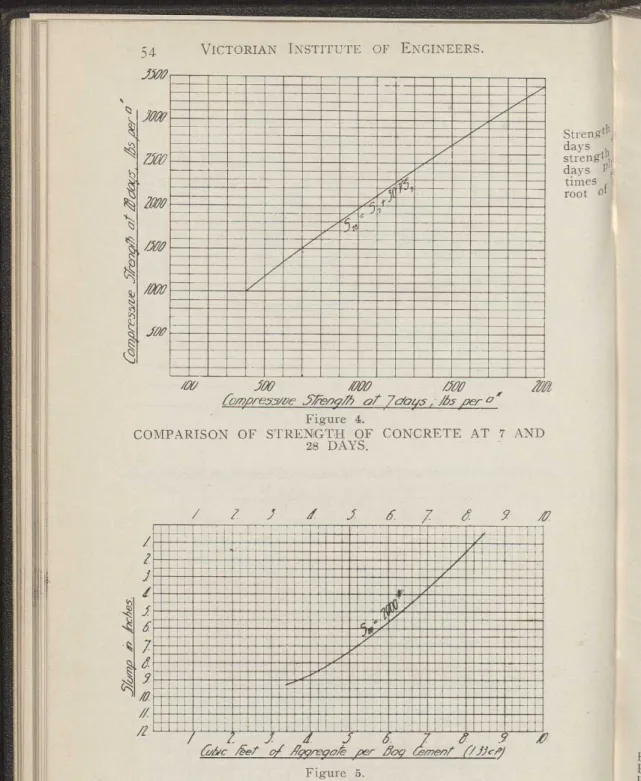
(c) After a period of 48 hours the cylinders are re- moved from the moulds and buried in damp sand till required in the testing laboratory. Tests are usually carried out in 7 to 28 days. The strength
,
~
~h
in 28 days can be very closely approximated from
I the following equation:—
S =Splus30VS
1111 Fig. 4 shows this graphically.
I might point out that I have seen testing engineers from municipal and private firms taking compression tests in 6 in.
diameter x 6 in. high moulds. This is liable to lead to false values, as the angle of rupture (approximately 6o deg.) in many cases comes inside the diameter of fhe. cylinder.
Another point in regard to the testing of concrete work worthy of mention is the fact that some of the municipal authorities refuse to place their test cylinders in damp sand,
/O. IO .JO DO . fO
fcarcenfo9e a/ rias-
Figure 11.
1'ABLE SHOWING COMPRESSIVE STRENGTH OF 1:3 CEMENT AND SAND IN 7 DAYS WITH VARIOUS PERCENTAGES OF
VOIDS IN SAND.
and in several cases I have seen them out in the sun when the sun temperature has been over the too deg. F. Their explan- ation for such action is that the cylinders should be cured in the same manner as the work it is a sample of, but this is not carried out, as the materials in the work, with the prob- able exception of the slabs, are all in large bulk protected by
moist forms on all sides, and the slabs are always kept wet for several days if the weather is at all dry.
The author is indebted to Professor Duff Abrams, of the Portland Cement Association (U.S.A.), for several of the aesigns curves in this paper for illustrating the water-ce- ment ratio and the fineness modulus, which in some cases have been amended to suit Australian conditions.
The PRESIDENT moved a hearty vote of thanks to Mr.
Lang for his interesting lecture. The lecture had cost Mr.
Lang a great deal of time to prepare, and it was not fair to the author to proceed to discuss it at such short notice. He would suggest that the discussion be postponed until they had had an opportunity of studying the paper, when it was hoped an interesting discussion would ensue. They should express to Mr. Lang their appreciation of his kindness in reading the paper.
The vote of thanks was carried with acclamation.
!YA/er.
6,a//s. per cemer~
~ /./~/
CìA//s. per ba,4-s60~D
5500 5000 4500 4000 3500
3000 2500 2iVO /5a
.4 -5 •6 •7 d •9 /0 // /2 // /4 /5 GYn/er - Germen/ IFia/io . by ✓o/ume.
Figure 1.
RELATION BETWEEN WATER-CEMENT RATIO AND STRENGTH.
Water
X = by Volume.
Cement
14000 Curve A
7.X.
14000 Curve B =
9. X.
S,ève
S-/ , g- S7a/--7 F~ef~
'rave/
/ef ~
/00 /00 /00
50 94' %OD
30 52 /00
/G 29-5 /OO ff /5 /00 4' 3 9.5- i g 67
B3 a g 21
~ 2 a
0 0
WI 2_915- /00 Hg /W-2.93 /líl- =6:90
Sieve Saes
Figure 2. CALCULATION OF FINENESS MODULUS
/47'ea/ Nlix v/i,mes at d//ixB~1 Aggreg ii for each v/time pf ~srni~f N
71
lull JUli _
G'11i~ i•M~~ ~~ ~NM ■ \MM ■■ ■■■
► ~ ■ ► es• ► _ ._ ■■■
í~ i ,~ % _~. ■ m- ~ ■■■
~ rh~~/ Ali~~ i ► ~ ■■■■■ ■ ~ ■■ ~~~ ~ °~ ■■ ■ ~ ~
~mm ■ ~
4,
Figure 3A.
Slump 2 in. to 1 in.
Re.a!/ MX v/ /-2.7es Mixred Aggregnfe fr e~rch v-srr~e of Gerr.rer7f
O w °o
riiil ■ 11\Mall11111
"
111 ■ ~1'~ ► ~\°
~~ ~~~~ ► : E~~~ _~í~r\1~ ,.
. Í~~ ■ 11~1r`v
rii %\~ ► ~ ► ~ '
Ip
3
c‹)
,n.
/2
í+l
Figure 3G.
Slump 6 in to 7 in
RELATION BETWEEN VARIOUS FACTORS AND STRENGTH.
Rea/ M;r v mes :4ggrega7`e for eaeói &Z-ime of Geme1-7f
N w A \)) N
16
• 1•1111~111•1111 ~ ;
In1vlm1_srmirmmumm INEEM\EeILG ► ~®E
• 1111111:1•1111•11111
• ® N~ ~/ ~ _
■ •1111i~1
M 1111
•••a•1111
Figure 3B.
Slump 3 in. to 4 in.
Rea/ /WA' K4/mes of-b/iredAggreggfe fr earoh v/-#77e of Gemerr/
N
96
mow
74
Figure 3D.
Slump 8 in. to 10 in.
RELATION BETWEEN VARIOUS FACTORS AND STRENGTH.
.4A
71
Strength days strengt 11 days P
times root of
J
tb
~
JOo
1
~
~
s 6
B7
/D //
/GY/ J00 /000 /J00
~ampr-es5irre ✓%rrnyrh oT 7doys , /6s per- o ~ Figure 4.
COMPARISON OF STRENGTH OF CONCRETE AT 7 AND 28 DAYS.
JJ%0
1004
, ..
(Zbc /get d O
Ayyrz'yof Bog erne/7i ~ifjenJ Figure 5.
TABLE SHOWING THE AMOUNT OF AGGREGATE THAT MAY BE ADDED PER BAG OF CEMENT FOR A 2000 LB. CONCRETE
WITH VARIOUS SLUMPS.
Bag of Cement = 1.33 cu. ft. = 125 lbs.
Note.—The above quantities are based on a Fineness Modulus of 5.4, which is an average value of Frankston sand and ; in. screen- ings (without 2 in. screened out) mixed in the proportions of 40:60.
/1.
iu •mmn •u•• ■ • ■ ==m iismmm ■
i•■■~•w~•i■■■n■■u•~■■■••ii 13.11111111 ■■■■
■■iiiiMii
i~i
■■u■■u■■ ■~■■■■■■■uu■■■■■■■u► ■■ ■uu
■■ u■■u■■• u a
i■ uu ■■■■■■■■■ u ■■■ u■
r.~u
~i■■uu• i~~in■■ iii iiii i■ iâi,r~iniu■
~•
uu~■iiú■ ■■■
~pBpN
■■■■■■
p~N
p~~~■H■n■pr~N~~■ä~~•
~~~N.~■p~If.,i'.R%■~I•~~■■n■~~B■g■~■■■N
~■■~■■■■■■~■n■p■■■■■■B■~~■~~1■■~~~~~~~■p■■N■■
ii i n ■í ~ ■■ i ■ ~i ■ ° ■ ■ ~iiN ~ N is~ n ■ ■i i i
~■
n
~~~■ iii ú iii i
~ú
~■■
~■■~~N~~~N■■~..~~p■••■B■■■~•u•~E
■
•~I
~■~■■
~
Nu■
~~,NN~p■ uN,,%~■■■■■niiriiiiinii'■ C■iiiüu
n■i~n■üngii■~■■■■~■iiiii■ ■■~i■■ii■ii■i°x
~■■q• N1111•N•••■N■~N••■■~••111111■NMINIMMII
ii• ■ ■■ u ' ~
■i■iiii ■ u ■ i ■ ~~• ■
iii
ii~ii n ■ ■ii
ii~
_77
2 ) .l .f 6 7 e 9 /p /Mx- V/ame of Arco' 4 9-6 jam. f 164.
ineo/
Fnvnen/Figure 6.
CEMENT PER CUBIC YARD OF CONCRETE.
Note.-i c. foot cement = 94 lbs.
1 bag = 1.33 c. ft. = 125 lbs.
1 2- 3 4 5 6 7 8 9
Dry Dry
P er cent. Water (by wgt.) 0 Rodded. Loose. Loose. Loose. Loose. Loose. Loose. Loose. Inundated 0 1 2+ 5 7+ 10 15 20
W
Per. cent. Bulking V. per c. ft. (incl. r cent. Loss per c. ft. 0 0 5.8 15.2 345.2 13.2 25.6 30.2 29.0 27.7 19.7 1.7 .5 43.3 41.0 38.6 24.6 1.8
`
water) • .. 108 lbs. 102 94.5 82.4 79.3 82.4 85.8 99.5 127 lbs . '81.' Dry Sand in 1 c.
108 lbs. 102 93.6 80.4 75.5 76.6 78.0 86.6 106 lbs.
All percentages based on No. 1 Tube Dry Rodded Sand.
Figure 7 ,ngth
ngth s es of ta