This confirms that this project and thesis titled "Advanced Residual Current Circuit Breaker". carried out by the following students under my direct supervision and this work was carried out in the laboratories of the Department of Electrical and Electronics Engineering at the Faculty of Engineering, Daffodil International University in partial fulfillment of the requirements for the degree of Bachelor of Science in Electrical and Electronics Engineering. Project entitled "Advanced residual current circuit breaker". submitted by Khandaker Mehedi Hasan, Personal Number amp; Sabbir Hossain, ID No Session: Fall 2018 was accepted as satisfactory in December 2018 in partial fulfillment of the requirements for the degree of Bachelor of Electrical and Electronics Engineering.
LIST OF TABLES
ACKNOWLEDGEMENT
ABSTRACT
One of the saddest things about using electricity is through the death of a person by electricity. In this paper, we introduce a circuit breaker that can protect a person from death by electrocution. This circuit breaker is basically a differential circuit breaker which measures the current of phase and neutral and if there is a small interruption it detects and trips the circuit breaker.
Currently, such switches are available which are analog and therefore the sensitivity is very low. We put it in digital mode and its sensitivity is so high that it is very effective in saving a person's life.
INTRODUCTION
- Introduction
- Problem Definition
- The Effects of Electric Shock
- Solution of The Problem
- Objectives
- Scopes and Limitation
- Methodology
- Project Outline
When the body of the Victim touches the line, the current flows through the body and goes into the ground through the body. The cost of the device is very low and after the mass production it will cost up to 500 BDT. This device can be used with the main switch of every residence and can also be used in crowded electrically dangerous places.
This device can be used in residential homes and can also be used for industrial purposes in the future. This device is based on electronic components and these may become damaged and stop working. In this section we will discuss what our problem is, how we can tackle this problem and what the future goal of the project will be.
In this part, the total cost of the project, details of the result were discussed. In this section we talk about the future goal of the project and how to get more benefit from the work.
LITERATURE REVIEWS
- Related Works and Existing System
- RCCB
- Purpose of RCCB
- Types of RCCB
- Working principle of RCCB
- Limitations of the RCCB
- Proposed RCCB and Difference with Existing RCCB
- The limitation we worked with
- Description of Block Diagram
- Circuit Diagram
- Working procedure of the circuit diagram
- List of the components used in the circuit
- Summery
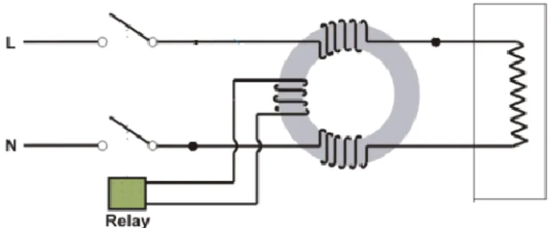
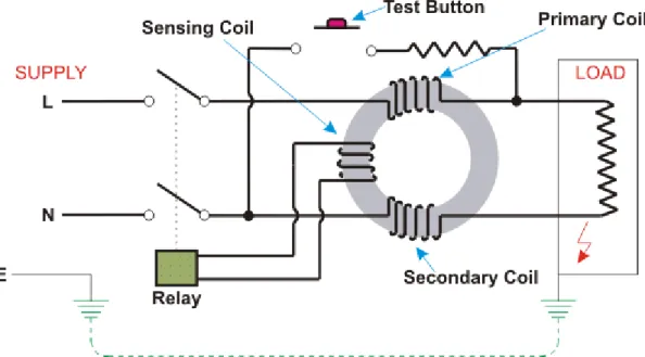
Two poles: It consists of two poles, one is a live wire and another is the neutral wire. RCCB works on the principle of "Kirchoff's current law" as the input current is equal to the output current. This switch is made in such a way that the incoming current through a live wire does not match the outgoing current through the neutral wire, which means that the fault current occurs.
Primary coil containing the live line, secondary coil containing neutral line, which produces equal and opposite flux if the current in both lines is the same. When a fault occurs, there is the difference between the live line and the neutral line, the relay coil detects the difference and trips the coil. This is primarily because the RCCB is designed to operate on a typical supply waveform.
We propose to bring a digital system that starts sensing from the current of 0.04 mA, which is not possible in analog way. In the case of very small current differences, the amount of current generated in the current transformer does not turn on the relay. The current value found in the current transformer will be amplified so that its data can be analyzed.
The data will then be fed into the Arduino Uno and if an error is detected, the Arduino will turn on the circuit breaker according to its command. Here, the Arduino will be powered by the power supply while simultaneously connected to the amplifier and relay. When a fault occurs, the current transformer will pick it up by producing a certain amount of current.
D9 is connected to the relay module and when the relay module receives a 5V signal, it turns on the relay and opens the circuit. In this chapter we have discussed the history of the existing device, block diagram and circuit diagram of the proposed device.
DESCRIPTION OF COMPONENTS
- Introduction
- RCCB
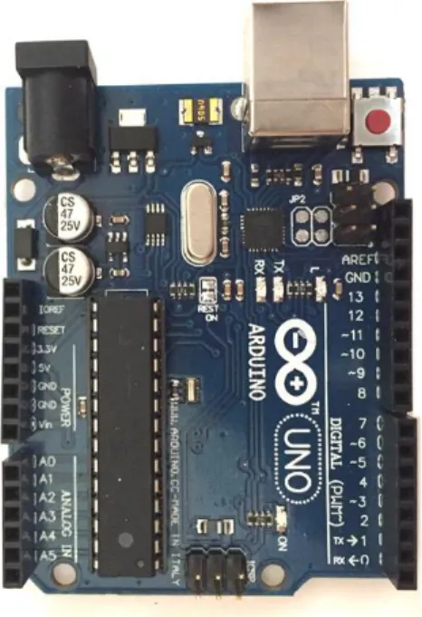
- The Arduino Uno
- Pin diagram of Arduino UNO R3
- Short description of the pins
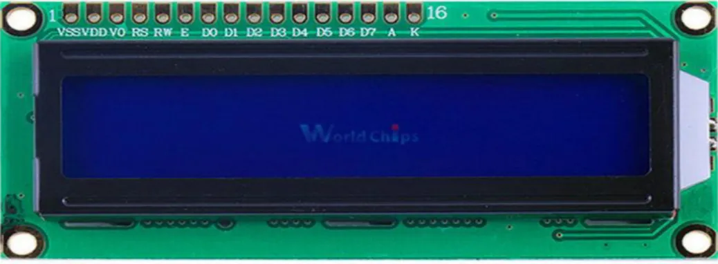
- LCD Display
- Pin Specification of LCD1602
- Ferrit Core(Ring Type)
- Applications for Buzzer Typical uses of buzzers include
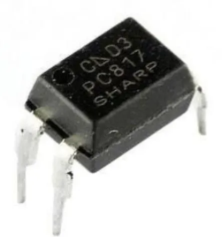
- Optocoupler (PC817)
- PC817 Feature
- Veroboard
- Relay
- Potentiometer 10K
- Current Transformer
- Transistor BC547
- Transistor BD907
- Diode 1N4007
- Resistor 47K
- Incandescent light bulb
- Transformer
- Capacitor (1000uf 16V)
- LM7805 Voltage Regulator
It has everything to support the microcontroller, a USB cable is used to connect to the computers and it is also used to power it with an AC-to-DC adapter or battery to start. It is composed of 5*7 or 5*11 matrix for positions, each of these positions represents a character. In this project, we use a ferrite core to measure the difference between the current between the two poles.
A buzzer is an analog electronic device that is used in an alarm device, timer doorbell and in another device. When an appropriate voltage is applied to the leads, electrons are able to recombine with electron holes within the device, releasing energy in the form of photons. This impact is known as electroluminescence, and the color of the light (similar to the electricity of the photon) is determined using the power band gap of the semiconductor.
The main feature of the PC817 is that it connects to the circuit section optically rather than electrically. It is distributed as a general-purpose fabric for use in the construction of electronic circuits - varying from published designed-for-purpose circuit boards (PCBs) to that many electronic circuits can be built using a preferred board of electrical installations. In this circuit, this component is used to connect between the 5 volt power supply and the Arduino pin D2.
It is electrically compatible with other rectifiers and any other 1N400X series diode can be substituted. A resistor is a 2 terminal passive component used in a circuit to limit current. It is also used to divide voltage, control signal level, terminate transmission lines, etc.
An incandescent bulb is an electric lamp that uses the wire filament to heat up and make the light glow. A transformer is a static device that transfers the electrical energy from the primary side to the secondary side without changing the frequency.
ANALYSIS
- Analysis of Trigger current
- Flowchart
- Circuit Design
- Hardware Design
- Summary of the chapter
We have built the circuit to simulate the project using Proteus v7.8 which is shown in Fig. Proteus is a simulation and design software tool developed by Labcenter Electronics for electrical and electronic circuit design. It has ISIS which is used for circuit design with simulation and ARES which is used for PCB design [16].
ISIS is the software used to draw schematics and simulate the circuits in real time. It has the function of viewing the output in a 3D view of the designed PCB along with components. It has sources, signal generators, measurement and analysis tools such as oscilloscope, voltmeter, ammeter, etc.
ARES offers PCB design up to 14 inner layers, with surface mounting and via whole packages. It is embedded with the footprints of various categories of components, such as ICs, transistors, headers, connectors and other discrete components. Proteus is the convenient and most essential software with the latest technology for circuit implementation and simulation.
Including necessary components with corresponding information from its library, it can be simulated after the circuit is set up. The microcontroller must include the hex file for the execution of the entire project. Proteus combines circuit simulation to facilitate the co-simulation of complete microcontroller-based designs [15]. We use this software because it is very user friendly to design and simulate any circuits than using other software.
The equipment used for designing and implementing the following circuit is Arduino Uno R3, LCD Display, Buzzer, and other components. In this chapter we have shown an analysis of trigger current, a block diagram of the project, Circuit design of the project, Flow diagram of command and posted a precise picture of the project.

RESULT AND DISCUSSION
- Result
- Discussion of Result
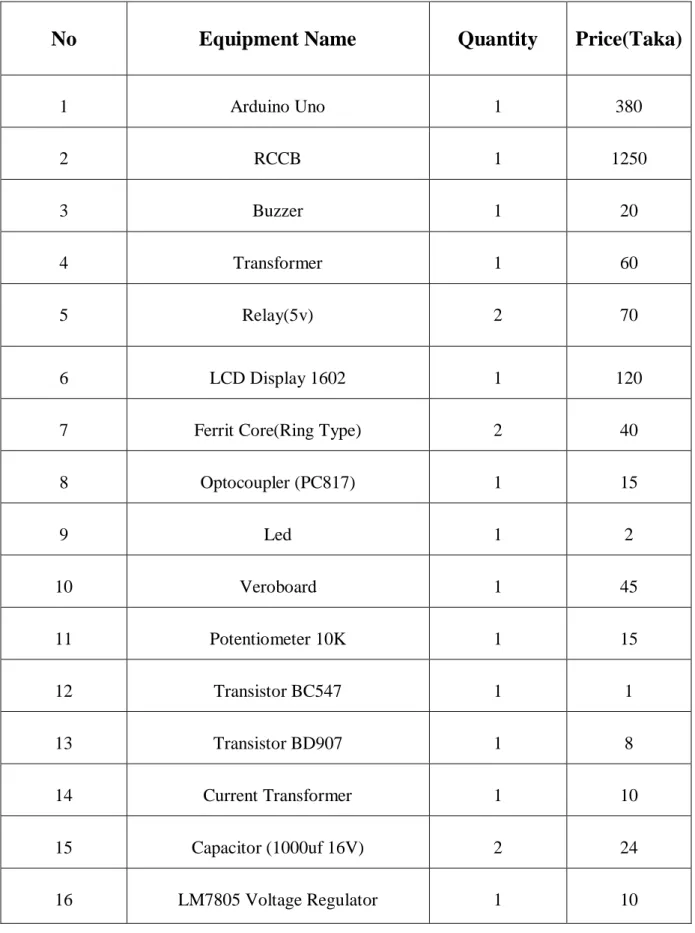
- Cost Analysis
- Cost Comparison
- Summary of the chapter
In the future, by using a small 4-pin microcontroller IC instead of Arduino, the cost will be greatly reduced in terms of production and mass production. So we can say that the cost of our project is much less than the cost of the existing product and there are much more benefits than the existing product. In this chapter we have discussed the results of the project and compared the costs of the existing system with its costs.
Here we have come to the realization that our proposed idea is the best idea.
CONCLUSIONS
- Conclusion
- Limitation of the Study
- Future Works
- Summary of the chapter
As a first step in the transition from analogue technology to digital technology, our project will play a leading role.
Appendix