This is to certify that this project titled “MICROCONTROL BASED INTERMITTENT AUTOMATIC TRANSFER SWITCH” was done by the following students under my direct supervision. The thesis project work was carried out by them in the laboratories of the Department of Electrical and Electronic Engineering under the Faculty of Engineering, Daffodil International University in partial fulfillment of the requirements for the degree of Bachelor of Science in Electrical and Electronic Engineering. Sanuar Hossan Shohag, ID Session: Fall 2018 has been accepted as satisfactory in partial fulfillment of the requirements for the degree of Bachelor of Science in Electrical and Electronics Engineering December 2018. Automatic Transfer Switching System In Current 16 How a Circuit Breaker Works auto transfer 18 Features review of our auto transfer switch 19.
Schematic diagram of a typical transfer switch Block diagram of the overall system design Standard automatic transfer switch. Switched Mode Power Supply Automatic Transfer Switch Light Emitting Diode Liquid Crystal Display Internet Service Provider Serial Peripheral Interface bus Power Supply Unit. The structured hardware enterprise has changed to targeted use of configuration pack programming.
The duplicate outcomes confirmed the strategy used in this way and confirmed the usefulness of the proposed form.
INTRODUCTION
- General Information
- History
- Background Study
- Project Objectives
While there is a disappointment in an important power framework, the ATS invokes a backup power source, such as an uninterruptible power supply. ATS can also gradually begin to operate long-distance reinforcement frameworks, such as community diesel generators, to run electrical hardware until the moment electricity is restored. Initially, these switches were intended for guiding tasks, but with the branching out within the revolutionary development of electrical manipulation and mechanization, computerized transfer switches (ATS) were produced.
CHAPTER2
PROJECT REVIEW
GENERAL INFORMATION
The Automatic Transfer Switching System in Present
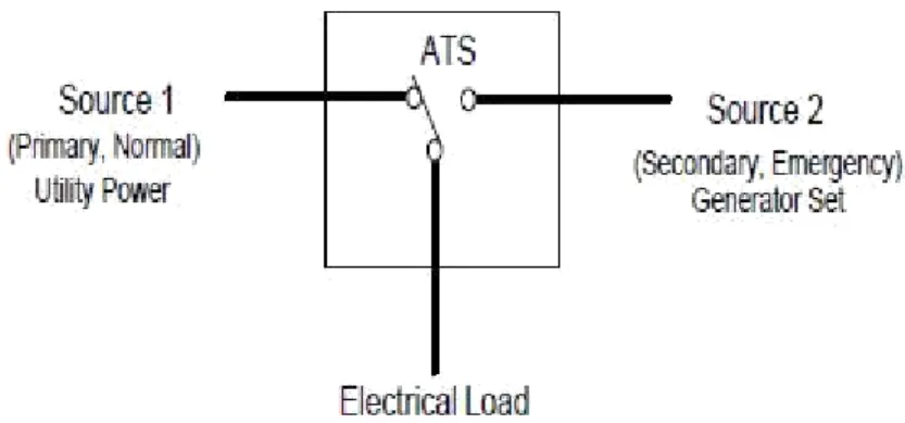
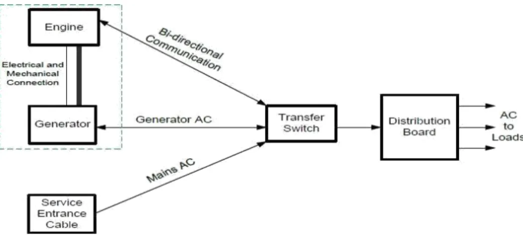
The switch must have the ability to sense the loss or fluctuation of power from the main source and, based on that stimulus, initiate and carry out the process of transfer from the source to the load. The ATS can consistently monitor all sources for over/undervoltage and current conditions or total power loss and issue an appropriate command for load transfer to an alternate power source. 4 show a block diagram of the overall system design and the block diagram of the ATS, respectively (Anderson, 2003).
The system hardware consists primarily of a transfer switch (TS) microcontroller, which serves as the master control device to which all other devices are connected. AC voltage sensing circuits detect the AC state from the grid and generator and communicate it to the TS microcontroller. A source changeover relay acts as a switching device to switch power sources between the grid and the generator to the load.
The TS microcontroller monitors the state of charge of a battery that supplies power to the entire control circuit.
Voltage Sensing Circuit
- How does an automatic transfer switch operate
- Our Automatic Transfer Switch Characteristics and Review
- Why Our ATS is Non-Interrupted
- Worked By Source Priority
- Description about Amperes vs. Timing
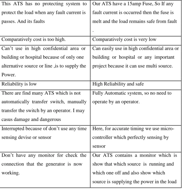
- Difference between Our ATS & Existing ATS in Market
- Why our ATS is Effective
- Block Diagram
- Schematics Diagram
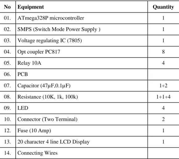
- Equipment Uses in the Circuit
Two AC voltage sensing circuits continuously monitor the condition of the utility supply, generator and communicate this to the TS microcontrollers. To ensure that 6 V TTL requirement of the microcontroller is not violated, a voltage divider circuit consisting of R1 and R2 is used to output approximately 5 V to the controller. The values of R1 and R2 are deliberately chosen in the kiloohm range to limit the sink current to the microcontroller.
The diode and capacitor C1 are used to provide a unidirectional DC current to the respective input pin of the microcontroller. The alternate switch works by having a dedicated association of switches for each of the circuits you want to control. Programmed switch Switches are used to guarantee the development of depth delivery, regardless of the fact that this may imply different things in different occasions.
There are some unique approaches that ATS can watch that the disturbance is fairly concise - by including batteries to fill in the hole from the stop of open application potential to the start of the boost generator delivers. From getting 8-24 volts 7805 IC yield five volts settled, it is the ship to the smaller scale controller for reliable switching on, in light of the reality that miniaturized scale controller wants set 5v to show up. For wreck before it was made, it changed into planned within the way the capacity to the heap can be cut off earlier than load changed into moved to order management.
The advantage of the plan is that the primary electricity supply and the backup electricity can never run in parallel during the switchover. Our progressive world has become increasingly attached to the incessant and accessibility of electrical energy. All insightful advancements, for example, Automatic Way Management (APC), depend on the power being free from interference or disturbing effects.
Transfer Logic Controller to monitor the state of the power sources and provide the control signals to the power switching unit. It consists of a series of relay contactors and protective devices that help form the control circuit of the ATS. The delay timer multi-function relays from the utility and generator sections provide some delays before.
The block diagram of the principle of operation of the ATS is shown in the figure.

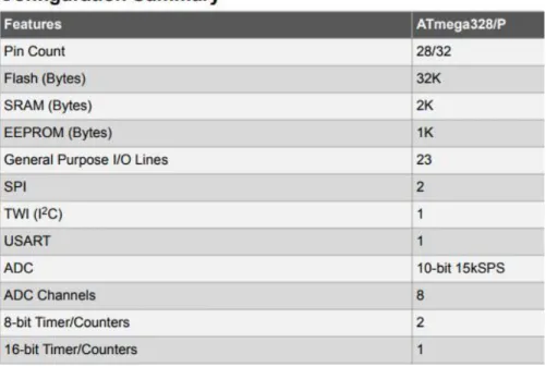
ATmega328p
- Configuration
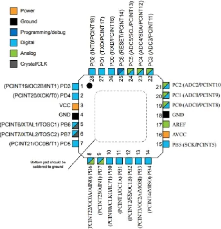
- Pin Configurations
- Advantages
- Switched Mode Power Supply (SMPS)
- Light Emitting Diode (LED)
- Voltage Regulating IC
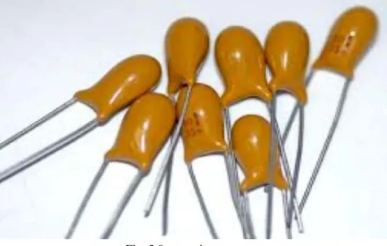
- Capacitor
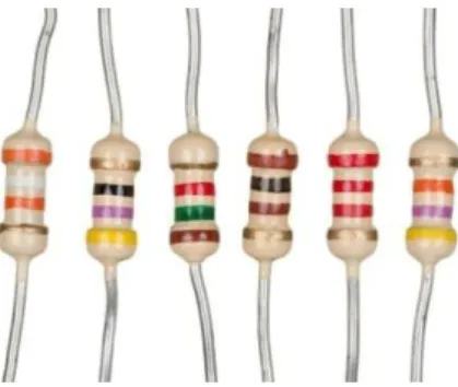
- Resistor
- Theory of operation
- Relay
- Operation
- Connector
- Opt-Coupler PC817
- Opt-Coupler Functions
In power saving mode, the beater clock continues to run, enabling the consumer to maintain the clock base at the same time as whatever remains of the device is being absorbed. In standby mode, the gem oscillator/resonator is running while all that is left of the machine is at rest. The vast majority of dc-to-dc converters used in SMPS circuits have a high mid-pass air exchange level to inspire the use of a high-pass transformer for voltage scaling and decoupling.
The high repetition transformer used in an SMPS circuit is much smaller in length and weight as opposed to the low repetition transformer in the instantaneous power supply circuit. In "ON" mode, the transfer is in immersion mode with negligible voltage drop across the collector and maker terminals of the switch, in which as in. The percentage of ON time to technique length (ON + OFF time) is known as the duty percentage of the chopper circuit.
A high replacement repetition (of the request of a hundred KHz) and a quick authority over the operating percentage results using the best suggest voltage along with swell voltage with a high repetition to the yield side, consisting of a low-pass channel circuit pursued with the aid of the stack. In some cases, the current-limiting features of the 78xx devices can provide protection not only for the 78xx itself, but also for other parts of the circuit. Be that as it may, a displacement current can move if an accelerating or alternating voltage is applied across the capacitor leads.
Capacitance is communicated as the ratio of the electrical price (Q) on each conveyor belt to the potential evaluation (V) under the individual in question. Run of the mill capacitance values move from about 1 pF (10−12 F) to about 1 mF (10−three F). The capacitance is significantly greater while there is a smaller separation between conductors and while the conductors have a larger floor area. Usually a machine is given to speed up the killing of the MOSFET while switching off the control input.
Such premature intrusions in a circuit containing a wide inductance could normally cause significant voltage spikes due to the surprisingly attractive drop of the object around the inductance. One of the advantages of electromechanical transfers over solid state switches is that the transfers have much lower contact competition. This empty material falls to the bottom of the photo transistor, causing it to turn on and conduct comparable to the average bipolar transistor.
The extraterrestrial response of the LED and the photosensitive system are tightly coordinated as they are isolated by a simple medium such as glass, plastic or air.
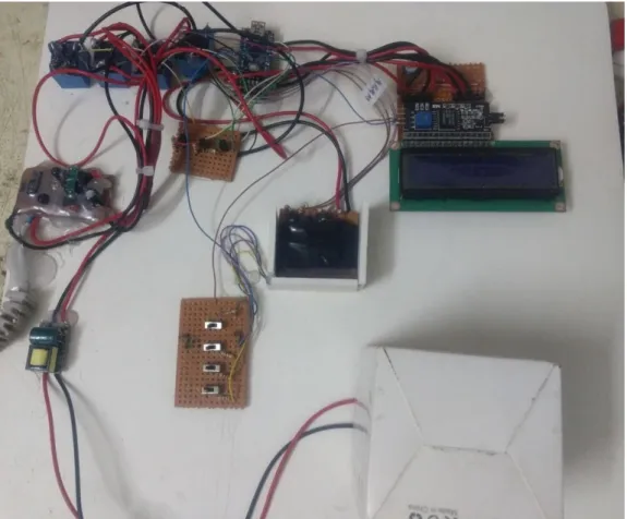
HARDWARE IMPLEMENTATION
- Introduction
- The Relay switching stage
- The Timer relay Stage
- CONTACTOR SELECTION
- The Power Supply Unit (PSU)
- Cost Analysis
- Result
The comparison between relay and time delay transfers is the point at which the yield contacts open and close: in a tamper transfer this occurs while the voltage is being applied and dissipated from the loop; in time delay transfers the contacts may open or close earlier or after some delay. At the point when time has elapsed, the contacts close - and remain closed until the point where the voltage is expelled from the loop. If the voltage is evacuated before the timeout, the time delay is reset. 4.4 The switching stage of the contactor.
Contactors typically have several contacts, and these contacts are usually (but now not commonly) generally open, with the intention that the ability to the pile is shut off while the curl is de-inspired. With the info voltage supplied from both control sources (V) = 220-240Va.c supply Generator manipulate rating (P) = 2.5KVA. The aspect of the PSU looking outside the case has a 3-pin male port to which a power hyperlink connected to a power source connects.
Large bundles of colored wires extend from the opposite side of the power supply unit into the laptop. Plugs on the opposite closures of the wires cooperate with different segments inside the computer. Some are explicitly intended to connect to the motherboard, while others have connectors that fit fans, floppy drives, hard drives, optical drives, or even a few powerful video game cards.
Power distribution devices are rated by wattage to indicate how much power they are able to deliver to the laptop. For the reason that every laptop element requires a chosen degree of ability to paint legitimately, it's vital to have a PSU that can deliver the exact amount. In the middle of the positive half cycles, diodes D2 and D3 are forward biased and current actions through the terminals.
Due to the fact that load leading edge is a similar way in every 1/2 cycle, full wave rectifier flag appears across the terminals. Be that as it may, the clock transfers provide delay of 5 seconds amid starting the generator and transferring the related load and the.
CONCLUSIONS & RECOMMENDATIONS
CONCLUSION
RECOMMENDATION
ELECTRICAL ENGINEER'S PORTABLE HANDBOOK – ROBERT B. HICKEY
APPENDIX A