This is to certify that the thesis titled, "EXPERIMENTAL STUDY ON THE PERFORMANCE OF A MECHANICALLY INDUCED DRAFT COOLING TOWER WITH DIFFERENT AMOUNTS OF CIRCULATING LIQUID" is a result of the investigation carried out by the author, M. Senior Instructor and Head of Department , Department of Mechanical Engineering, MIST. Natural and induced cooling tower and the computer program gives us the various data needed for the calculation.
Introduction
Objectives of Thesis
Historical Background
By 1970, the use of these cooling towers in commercial air conditioning systems accounted for about half of HVAC cooling tower installations. The performance characteristics of the centrifugal fan cooling tower have begun to give way to the energy reduction offered by the propeller fan units of industrial transverse cooling towers.
Motivation
Thesis Organization
Basic Concept
First Law of Thermodynamics
When a system undergoes a change of state, work and heat cross the system boundary and the properties of the system change. The chemical composition of the system does not change and therefore the chemical energy does not change either.
Second Law of Thermodynamics
The rate of mass inflow is the same as the rate of mass outflow and the mass of fluid remains constant within the system. From the above discussion it will be understood that the amount of heat transferred by all engines operating in the Carnot cycle and between the same temperature limits will be the same and therefore their efficiency will be equal.
Modes of Heat Transfer
Heat Transfer by Conduction
When a molecule from the high temperature region collides with a molecule from the low temperature region, it loses energy from the collisions.
Heat Transfer by Convection
Heat Transfer by Radiation
Cooling Tower
Types of Cooling Tower
- On the basis of Heat Transfer Mode
- On the Basis of Shape
- On the Basis of Construction
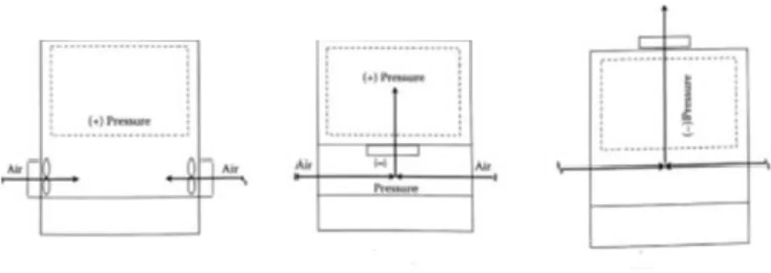
- On the Basis of Air Flow
- On the basis of Air Draft
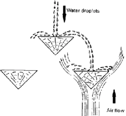
- On the basis of type of fill
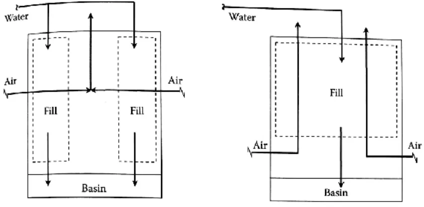
A natural draft tower (also known as a hyperbolic cooling tower) is similar to an atmospheric tower in that there is no mechanical device to create airflow through the tower. In this case, the fans are typically located at the point where the air enters the tower.
Mathematical Modeling
And the slope of the straight line (L/G), which is the ratio of the total mass flows of water and dry air in the cooling tower. The driving force behind the cooling process in the cooling tower is therefore the vertical difference between the water pipe and the air pipe.
Parameters
34;Approximation" is the difference between the cooling tower outlet cold water temperature and ambient wet bulb temperature. Cooling tower efficiency (in percentage) is the ratio of range, to the ideal range, i.e. difference between cooling water inlet temperature and ambient wet bulb temperature, or in other words it is = Range / (Range + Approach) Cooling capacity is the heat rejected in kCal/hr or TR, given as product of mass flow rate of water, specific heat and temperature difference.
The liquid/gas ratio (L/G) of a cooling tower is the ratio of the mass flow rate of water to air.
Component
- Cooling Tower
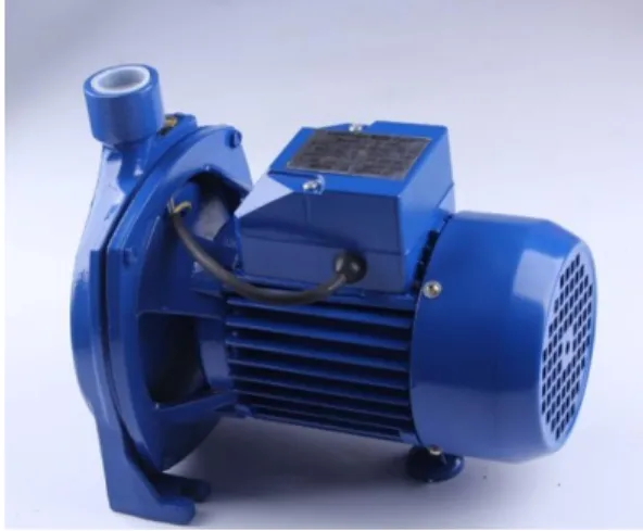
- Pump
- Reservoir
- Flow Meter
- Thermocouple
- Humidity Sensor
- Anemometer
- Thermocouple Controller
- Arduino
- Black Soot(Ink)
Humidity sensors or hygrometers can be classified based on the type of humidity they are used to measure, ie there are other types of humidity sensors or hygrometers such as optical hygrometer, oscillating hygrometer and gravimetric hygrometer. An anemometer is an instrument used to measure the speed or velocity of air (gases), either in a confined flow, such as airflow in a duct, or in unconfined flow, such as atmospheric wind.
A controller in a temperature control system will accept a temperature sensor such as a thermocouple or RTD as input and compare the actual temperature to the desired control temperature or set point. A good example would be an application where the controller receives an input from a temperature sensor and has an output that is connected to a control element such as a heater or fan. We used ink powder, which is the mixture used in laser printers and photocopiers.
With the use of new technologies such as emulsion aggregation, a further reduction in particle size is being developed, causing a further improvement in resolution.
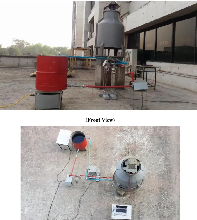
Developed Experimental Setup
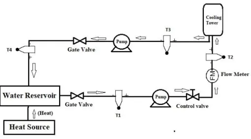
Schematic Diagram
Water Circuit
Ball valve-2 (for controlling the water flow rate) . Thermocouple-2 for measuring the water inlet temperature.) Thermocouple-1 (used for measuring the water inlet temperature.)
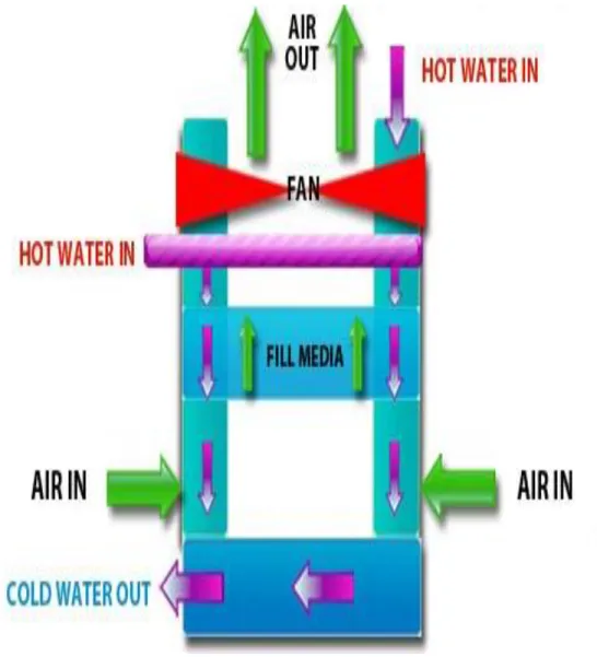
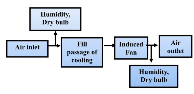
Air Circuit
Water Properties Measurement
Air properties measurement
Data Collection & Calculation
Cooling Tower Characteristics Analysis
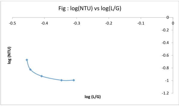
In this graph, a relationship was established between the efficiency and L/G of an induced draft cooling tower corresponding to the data shown in Appendix [A9]. In this graph, the relationship between log NTU and log L/G of an induced draft cooling tower was established, corresponding to the data shown in Appendix [A10]. In Figure (5.3) we see the exponential relationship between (𝐿 .. 𝐺)𝑛where n is the coefficient, the available coefficient of the cooling tower is defined as the point on the required coefficient curve at which the cooling tower will work for a certain operating condition.
In this graph, a relationship between the efficiency and the flow rate at constant inlet temperature of an induced draft cooling tower has been established in the case of induced draft, corresponding to the data shown in appendix [A12]. In this graph, a relationship between the efficiency and the flow rate at different inlet temperatures of an induced draft cooling tower has been established, corresponding to the data shown in appendix [A13]. In this figure, we can see that the cooling tower efficiency at different inlet temperatures with the decrease in water inlet temperature efficiency also decreases.
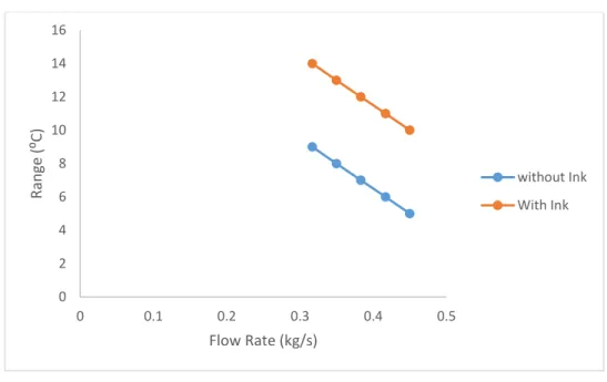
In this graph, a relationship is established between the flow rate and the range at 38 ⁰ C Inlet temperature of the induced draft cooling tower corresponding to the data presented in Appendix [A20].
Comparative Study of Performance of Induced & Natural Draft Cooling Tower
In this graph, a correlation has been established between efficiency and approach of natural and induced draft cooling tower corresponding to data shown in appendix [A4]. On the graph it has been seen that as approach increases efficiency also increases and we can also see that efficiency vs approach curve of induced draft is in much higher position than natural draft. In this graph, a correlation has been established between efficiency and flow rate of natural and induced draft cooling tower corresponding to the data shown in Appendix [A6].
In this graph we can observe at a constant inlet temperature but for a different flow rate. As the flow rate increases, the efficiency decreases and we can also see that the flow versus efficiency curve of the induced draft is at a much higher position than the natural draft. This graph establishes a relationship between the entering air wet bulb temperature and the leaving water temperature, natural cooling tower and induced draft cooling tower, corresponding to the data shown in Appendix [A5]. In this graph we can see that the efficiency of an induced draft cooling tower is higher than that of a natural draft cooling tower.
In this graph, a relationship between water inlet and range at the same flow rate of natural and induced draft cooling tower is established which is consistent with the data shown in Appendix [A7].
Effect of Ambient Humidity on Cooling Tower Performance
In this graph, a relationship was established between the efficiency and relative humidity of an induced draft cooling tower in the induced draft case, corresponding to the data shown in Appendix [A15]. In this graph, the flow versus efficiency ratio of an induced draft cooling tower at 38. In this graph, the flow versus efficiency ratio of a natural draft cooling tower at 38.
In this graph, a relationship between flow rate and evaporation loss of induced draft cooling tower at 38 ⁰ C inlet temperature and with coolant with ink water ratio of 100 ml/110 L has been established in the case of induced draft corresponding to the data shown in the appendix [ A 17 ]. In this graph, a correlation has been established between efficiency and ratio of ink water in induced draft cooling tower in the case of induced draft corresponding to data shown in Appendix [A 23]. In this graph, a relationship has been established between range and ratio of induced draft cooling tower in the case of induced draft corresponding to data shown in appendix [A 24].
In this graph, a correlation has been established between efficiency and flow rate of induced draft cooling tower in the case of induced draft corresponding to data shown in appendix [A 33]. In this graph, a correlation has been established between efficiency and NTU of induced draft cooling tower in the case of induced draft corresponding to data shown in Appendix [A 34]. In this graph, a correlation has been established between efficiency and L/G of induced draft cooling tower in case of induced draft corresponding to data shown in Appendix [A 35].
Comparison of Cooling Tower Performance with Cooling Fluid of Various Quality 82
Conclusion
The tower characteristics, efficiency, composition of water and heat loss due to evaporation of natural and induced draft cooling with different quality of circulating fluids were evaluated. It was found that when L/G increases, both efficiency and cooling tower characteristics were observed to increase. So we can see with decrease in flow rate efficiency and cooling tower characteristics decrease.
It has been found that due to the addition of toner with water the efficiency, range, evaporative heat loss increases. For induced draft efficiency and range increase by an average of 8% & 4°c respectively and for natural draft range, efficiency and range increase by 5% & 2° respectively. With the increase in percentage of toner in water, efficiency and range were observed to increase, which was shown graphically.
Limitations
Recommendation
3] Kamel Hooman, Hal Gurgenci, Zhiqiang Guan, Yuanshen Lu, Manuel Lucas, Cooling Tower and Heat Exchanger 2015, Proceedings of the 17th IAHR International Conference. 4] https://www.brooksinstrument.com/en/products/variable [5] http://www.thermometricscorp.com/thermocouple.html [6] https://www.thermocoupleinfo.com/. 7] https://www.electronicshub.org/humidity-sensor-types-working-principle/#Humidity_Sensors_Classification_and_Working_Principles [8] https://learn.sparkfun.com/tutorials/what-is-an-arduino.
9] Creation of a new model to predict cooling tower performance and determine energy saving opportunities through economizer operation by Pranav Yedatore Venkatesh University of Massachusets - Amherst, [email protected]. 10] http://www.power-eng.com/articles/print/volume-121/issue-7/features/cooling-tower-heat- transfer-fundamentals.html. 12] GopinathD, Gurumurthy, Akilan, Azhager, Manimaran, Prabhakaran "Analysis on Performance of Natural Draft Cooling Tower" Journal of Chemical and Pharmaceutical Sciences ISSN: 0974-2115.
Connect pin 2 of the sensor to any of your existing DHTPIN // Connect pin 4 (on the right) of the sensor to GROUND.

![Figure 3.8: Thermocouple Controller [7]](https://thumb-ap.123doks.com/thumbv2/filepdfnet/10965211.0/49.918.341.552.112.355/figure-3-8-thermocouple-controller-7.webp)