This thesis report entitled “IOT BASED AUTOMATIC CONTROL CIRCUIT BREAKER FOR TRANSMISSION LINE”, submitted by Rakib Hossain ID Sabuj Kumer Sarkar ID to the Department of Electrical and Electronic Engineering, Daffodil International University has been accepted as satisfactory in partial fulfillment of the requirements for the degree of Bachelor Science in Computer Science and Engineering and approved in respect of its style and content. This thesis is submitted to Daffodil International University for partial fulfillment of the requirement of the degree of B.Sc. This thesis, in whole or in part, has not been previously submitted for any degree.
I will remain forever indebted to the Department of Electrical Engineering, Daffodil International University, Bangladesh for giving me the scope to carry out this project, which is an indispensable fragment of my B. It was his unwavering guidance and motivation throughout the course of uncertainties and doubts that have helped me tremendously in moving forward with this project. I am also grateful to the faculties of Department of Electrical Engineering who offered their helpful hands during the development of our project.
Finally, I would like to acknowledge the contributions of my parents, family members and my friends for their constant and never-ending motivation.
ABSTRACT
INTRODUCTION
- INTRODUCTION
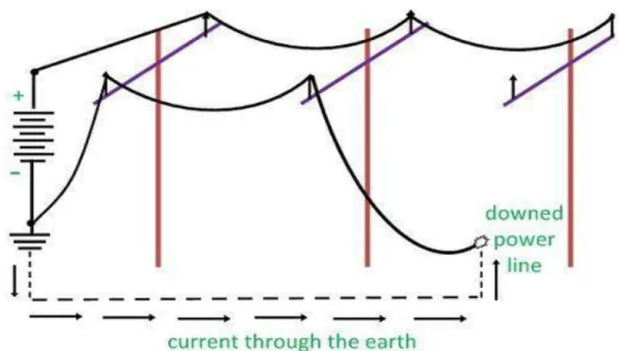
- SINGLE LINE TO GROUND FAULT
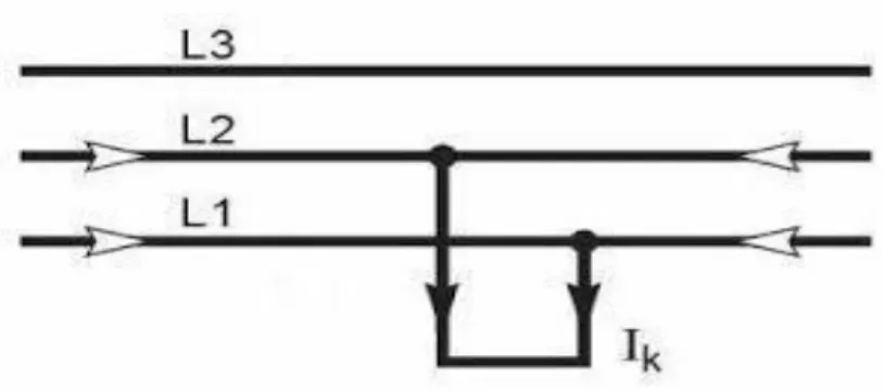
- LINE-TO-LINE FAULT
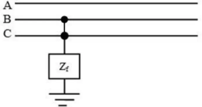
- Line-To-Ground Fault
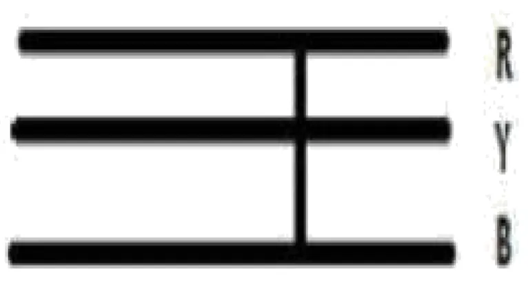
- BALANCE THREE PHASE
- PROPOSED METHOD FOR DETECTION AND PROTECTION OF FAULT
- IMPEDANCE AND FUNDAMENTAL FREQUENCY COMPONENT BASED METHODS
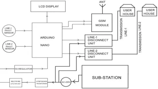
- BLOCK DIAGRAM FOR THESE PROJECTS
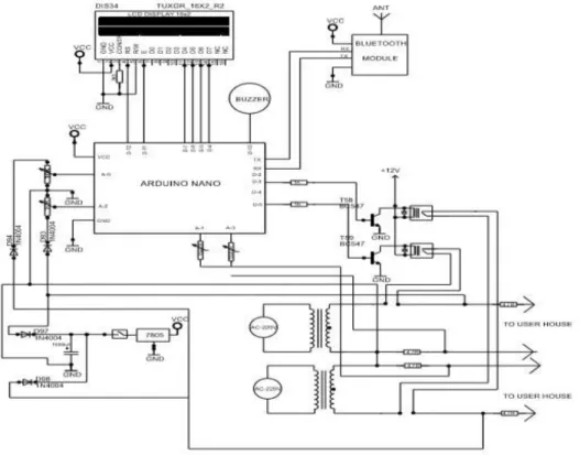
- CIRCUIT DIAGRAM FOR THESE PROJECTS
- WORKING PRINCIPLE
- EXISTING SYSTEMS
- FAULTS
- TECHNICAL DETAILS
This may be the result of a tree falling on two of the electric cables, or for various reasons. In this strategy, the rated voltage and current qualities are required on one or both sides of the bargain. In light of the program, the microcontroller analyzes these qualities to see if they are within the required range.
To stay away from such episodes to the utmost extent, support or checking of the transmission lines is usually completed on a sequential premise. Like in Western Ghats where the transmission lines are generally drawn in the middle of the timber field and places like Chiranjeevi where heavy rainfall brings almost everything to a standstill. Its advertiser, the GSM Association, estimates that 82% of the global versatile market uses the standard.
Its spread makes worldwide roaming extremely regular among cell phone administrators, empowering supporters to use their phones in numerous parts of the world.
GSM ARCHITECTURE
- SUBSCRIBER IDENTITY MODULE (SIM)
- WORKING OF GSM MODEM
- SHORT MESSAGE SERVICE (SMS)
- THE COMMUNICATION SYSTEM
- OPERATION OF THE GSM
- THE SWITCHING DEVICE RELAY
- OPERATION OF THE RELAY
- THE SENSING UNIT
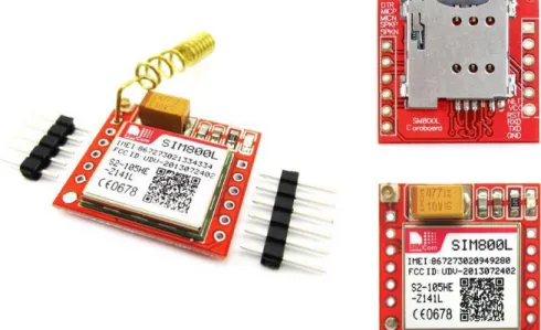
- SIM800L OVERVIEW
- POWER SUPPLY
- POWER SUPPLY PIN
- POWER ON SIM800L
- RESULT
- List of Component with Price
Depending on the setting, current electrical parameters can of course be sent occasionally in the form of an SMS. Whenever the set threshold is exceeded, the system sends a direct message to the utility's mobile phone, stating the existing fault and its location via the GSM modem. Characteristic of the GSM meters is this comprehensive arrangement of AT directions that enables the associated capabilities;
The delivery goes as an electrical break to disconnect the entire frame in the event of a fault. It shuts down or de-energizes other electrical equipment in the frame, which will then enable work to be done at a later time. As an electrical design for modified control, it is driven by the variety in electrical circuit conditions.
This voltage is required for the transfer to play out the capacity to open or close that contact. The attractive field inside the curl interruption, at whatever point there is an unexpected break in the progression of current through the delivery loop due to the contact opening. The sensing unit consists of the voltage sensing, current sensing, frequency sensing and temperature sensing as it helps to acquire electrical parameters and provide the respective signals for the PIC to process.
Daffodil International University 12 The SIM800L is a quad-band GSM/GPRS module that handles GSM850MHz, EGSM900MHz, DCS1800MHz and PCS1900MHz frequencies. Guaranteed that the data voltage never drops below 3.0V in any case when the current consumption rises to 2A in a transmit burst. This pin is now routed to VBAT inside the module so the external pull is irrelevant.
The moment a problem occurs on the transmission line, the board is sent to the control room or telephone via a GSM modem. The sign that appears on the control room or on the mobile phone is that there is a L*G or some other type of fault has occurred on the transmission line.
Hardware and Component
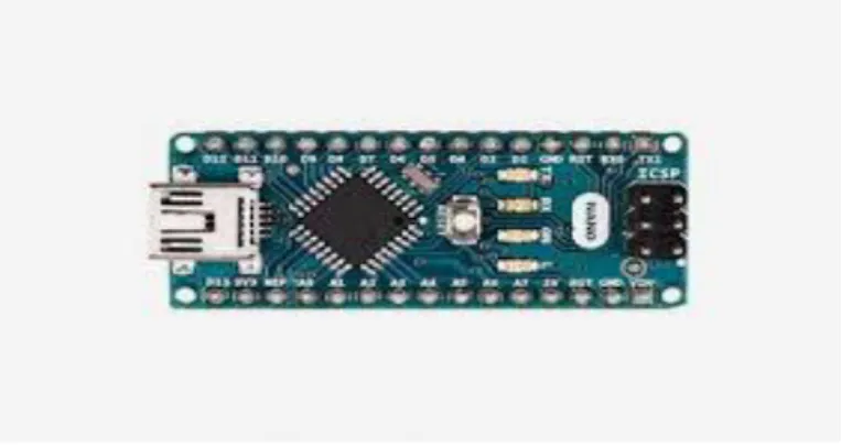
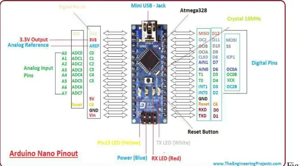
ARDUINO NANO MICROCONTROLLER BOARD
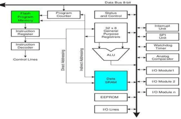
ARDUINO ARCHITECTURE
Daffodil International University 18 Power Jack: The Arduino can be controlled either from the PC via a USB or via an external source such as a plug or a battery. Power can be supplied externally through the Vin pin or by providing voltage reference through the Ref pin. Modernized Inputs: It contains 14 powered wellsprings of data/output sticks, all of which plus or minus up to 40mA current.
Some of them have interesting limits, such as pins 0 and 1, which go independently as Rx and Tx, for consecutive correspondence, pins 2 and 3 - where outside interferes, pins that give pwm output and pin 13 where LED relates takes along. Basic Information Sources: It has 6 basic data/yield sticks, each yielding a 10-bit objective. Arafa: It provides references to basic sources of information. Reset: It resets the microcontroller when it is low.
HOW TO PROGRAM AN ARDUINO
Daffodil International University 19 The Arduino device window contains the toolbar with the get like check, move, new, open, extra, sequential screen. It is like a way that involves a substance tool to form the code, a message area that shows the analysis like exhibiting the bundles, the substance convenience that shows the yield and a movement of menus like the file, edit, tools.
HOW TO DESIGN YOUR OWN ARDUINO
POWER SUPPLY
TRANSFORMER
Daffodil International University 21 extending the voltage increase to the transformer turns ratio and a current increase that inversely corresponds to the turns ratio control maintains the turns ratio = VP/VS=NP/Ns and current = control at or Vs.
WORKING OF THIS TRANSFORMER
DIODE
CHARACTERISTICS
FULL-WAVE RECTIFIERS
WORKING OF A BRIDGE RECTIFIER
CAPACITOR
THEORY OF OPERATION
The channels along these lines hold equivalent and opposite charges on their opposite surfaces, and the dielectric builds up an electric field. In SI units, a capacitance of one farad means that one coulomb of charge on each conductor causes a voltage of one volt across the gadget.
VOLTAGE REGULATOR
LCD MODULE
- ITRODUCTION
- HOW LCDs ARE CONSTRUCTED
- HOW LCD WORK
- Points of interest OF AN LCDs
- DISADVANTAGES OF AN LCDs
- BACKGROUND STUDY
- C PROGRAMENING CODE FOR THESE PROJECTS
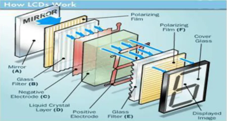
The liquid has an unusually small leeway in having low power utilization than the LCD or cathode ray tube. Liquid gems must be able to control both the activity to be transmitted or can likewise be ready to alter the activated light. As mentioned above, we need to take two energized pieces of glass that really take the form of the liquid gem.
The glass that does not have an activated film on the outside must be sanded with an extraordinary polymer that will create infinitesimal depressions on the outside of the cuffed glass channel. The standard behind LCDs is that when an electric current is applied to the liquid gemstone particle, the atom will generally untwist. This causes the edge of light to pass through the particle of the energized glass and also causes an adjustment in the tip of the upper polarization channel.
Therefore, some light is allowed to pass through the entrancing glass through a specific zone of the LCD screen. A connection pad is made of indium tin oxide held at the top and an activated glass with a polarizing film is also located in the base of the device. The total location of the LCD screen should be surrounded by a typical cathode or more, it should be the liquid gemstone problem. Then it goes to the second piece of glass with an anode as a square shape on the base and, on top, another polarizing film.
When there is no current, the light passes through the front of the LCD, it will be reflected by the mirror and shot back. Since the anode is associated with a battery, the current from it will cause the liquid gems between the normal flat terminal and the cathode which is shaped like a square to untwist. LCDs consist of a few microwatts for display as opposed to some plant watts for LCDs.
Innovation of liquid gems has significant applications in science and design also on electronic gadgets. The fluid bead show method is also relevant for representing the radio repetition waves in the waveguide.
HARDWARE INTEGRATION
- LINE ONE AND TWO OPEN
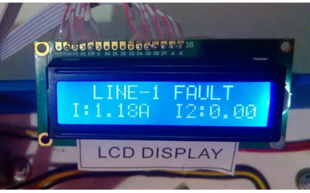
- LINE ONE FAULT
- picture of project
- CONCLUSIONS
- Future scope
That is why the line automatically turns off so that the line current goes to zero. Transistor is used to keep the circuit safe. When an error occurs, the circuit is unaffected by input and output filtering. We used two capacitors. Here in this venture we have planned a GSM based transmission line control and signing framework which transmits similar data to the control room through SMS.
It provides the best approach to identifying deficiencies, such as loss of vitality and breakdown of strength. In addition, he recognizes the shortcoming in time and henceforth maintains a strategic distance from the illegal use of force. Programmed verification, parsing and logging takes place on the PC screen via a hyper terminal.
The enterprise has a ceaseless observing framework that includes the GSM correspondence innovation and the microcontroller innovation. Using the framework will save enormous amounts of power and accordingly power will be accessible to increasing numbers of buyers in an exceptionally populous nation, for example, BANGLADESH. Here, in this task, we have planned a GSM-based transmission line sensing and signaling framework that sends data from the equivalent to power board through SMS.
We have met all the essential needs of running the simple substation and safety. The assignment we performed is certainly not the only task that the components can perform. The project “IOT-based Automatic Control Circuit Breaker for Transmission Line” aims to automate the certain function of a substation. The main scope of this project is that we can control substations using GSM and Arduino Nano.
With the latest expansion of communication network, substation overvoltage and overcurrent control by using this circuit.
Appendix