©Daffodil International University
“Simulation Based Comparative Study of EIGRP and OSPF Protocols for Real-Time Applications”
BY
Md.Salah Uddin ID: 073-19-813
AND
Md. Monjurul Hoque Chowdhury ID: 073-19-781
This Project Report is Presented in Partial Fulfillment of the Requirements for the Degree of Bachelor of Science in Electronics and Telecommunication Engineering
Supervised By
Mr. Md. Mirza Golam Rashed Assistant Professor
Department of ETE
Daffodil International University
DAFFODIL INTERNATIONAL UNIVERSITY
DHAKA, BANGLADESH
AUGUST 2012
©Daffodil International University
i APPROVAL
This Project Report titled “Simulation-Based Comparative Study of EIGRP and OSPF Protocols for Real-Time Applications”, submitted by Md. Salah Uddin and Md. Monjurul Hoque Chowdhury to the Department of Electronics and Telecommunication Engineering, Daffodil International University, has been accepted as satisfactory for the partial fulfillment of the requirements for the degree of B.Sc. in Electronics and Telecommunication Engineering and approved as to its style and contents. The presentation has been held on 28 August 2012.
BOARD OF EXAMINERS
(Dr. Md. Fayzur Rahman) Chairman Professor and Head
Department of ETE
Faculty of Science & Information Technology Daffodil International University
(Dr. A.K.M Fazlul Hoque) Internal Examiner Associate Professor
Department of ETE
Faculty of Science & Information Technology Daffodil International University
(Mr. Mirza Golam Rashed) Internal Examiner Assistant Professor
Department of ETE
Faculty of Science & Information Technology Daffodil International University
©Daffodil International University
(Dr. Subrata Kumar Aditya) External Examiner Professor & Chairman
Department of Applied Physics,
Electronics and Communication Engineering University of Dhaka
©Daffodil International University
DECLARATION
We,hereby declare that, this project has been done by us under the supervision of Mr. Md. Mirza Golam Rashed, Assistant Professor, Department of ETE Daffodil International University. We also declare that neither this project nor any part of this project has been submitted elsewhere for award of any degree or diploma.
Supervised by:
Mr. Md. Mirza Golam Rashed Assistant Professor
Department of ETE
Daffodil International University
Submitted by:
(Md. Salah Uddin) ID:
073-19-813
Department of ETE
Daffodil International University
(Md.Monjurul Hoque Chowdhury) ID: 073-19-781
Department of ETE
Daffodil International University
©Daffodil International University
ii ACKNOWLEDGEMENT
First we express our heartiest thanks and gratefulness to almighty Allah for His divine blessing makes us possible to complete this project successfully.
We fell grateful to and wish our profound our indebtedness to Mr.Md. Mirza Golam Rashed, Assistant Professor, Department of ETE Daffodil International University, Dhaka. Deep Knowledge & keen interest of our supervisor in the field of wireless network influenced us to carry out this project. His endless patience, scholarly guidance, continual encouragement , constant and energetic supervision, constructive criticism, valuable advice, reading many inferior draft and correcting them at all stage have made it possible to complete this project.
We would like to express our heartiest gratitude to Mr.Md. Mirza Golam Rashed, Assistant Professor, Department of ETE and Professor Dr.Md.Fayzur Rahman , Head, Department of ETE, for his kind help to finish our project and also to other faculty member and the staff of ETE department of Daffodil International University.
We would like to thank our entire course mates in Daffodil International University, who took part while completing the course work.
Finally, we must acknowledge with due respect the constant support and patients of our parents.
©Daffodil International University
iii
ABSTRACT
Routing protocol is taking a vital role in the modern communication networks. The performance of each routing protocol is different from each other. In the context of routing protocol performance, each of them has different architecture, adaptability, route processing delays and convergence capabilities. Among different routing protocols, Enhanced Interior Gateway Routing Protocol (EIGRP) and Open Shortest Path First (OSPF) have been considered as the pre-eminent routing protocols for the real-time application. EIGRP and OSPF are dynamic routing protocol.
There are various numbers of static and dynamic routing protocols available but it is very important to select a right protocol among them. This selection depends on several parameters such as network convergence time, network scalability and bandwidth requirements. Our thesis paper reports, a simulation based comparative performance analysis between EIGRP and OSPF for real time applications such as video streaming and voice conferencing. In order to evaluate the performance of EIGRP and OSPF, we designed a network models that are configured with EIGRP, OSPF respectively. The evaluation of the routing protocols is performed based on quantitative metrics such as convergence time, packet delay variation, endto-end delay, and throughput and packet loss through the simulated network models. The evaluation results show that EIGRP routing protocol provides a better performance than OSPF routing protocol for real time applications.
Keywords: EIGRP, OSPF,OPNET
©Daffodil International University
iv
TABLE OF CONTENTS
CONTENTS PAGE
BOARD OF EXAMINERS ... 2
DECLARATION ... 4
ACKNOWLEDGEMENT ... 5
ABSTRACT ... 6
CHAPTER1:INTRODUCTION
1.1 Introduction...11.2 Motivation ...2
1.3 Problem Statement and Main Contribution ...2
1.4 Disposition ...3
CHAPTER2:TECHNICAL OVERVIEW OF ROUTING PROTOCOLS
2.1 General Overview ...42.2 Characteristics of Routing Protocols ...4
2.3 Metrics and Routing ...5
2.3.1 Metrics ...5
2.3.2 Purpose of a Metric ...5
2.3.3 Metric Parameters ...5
2.4 Classification of Routing Protocols ...6
©Daffodil International University
2.5 Static versus Dynamic Routing...6
2.6 Classful and Classless Routing Protocols...7
2.6.1 Classful Routing ...7
2.6.2 Classless Routing ...8
2.7 Link State Routing ...9
2.8 Distance Vector Routing ...9
CHAPTER 3: OPEN SHORTEST PATH FIRST
3.1 Background ...11
3.2 OSPF Message Encapsulation ...11
3.3 OSPF Packet Header ...12
3.3.1 Version: ...12
3.3.2 Type: ...12
3.3.3 Router ID: ...12 3.3.4 Area ID: ...12
3.3.5 Checksum: ...12
3.3.6 Au Type: ...12
3.3.7 Authentication: ...13
3.4 OSPF Packet Types ...13
3.5 OSPF Area ...15
3.5.1 Backbone Area ...15
3.6 OSPF Cost ...16
3.7 OSPF Router Types...16
3.8 OSPF and Route Summarization ...17
©Daffodil International University
3.9 Link State Advertisement (LSA) ...19
3.10 Shortest Path First (SPF) Algorithm ...20
3.11 OSPF Convergence ...21
3.12 Advantages and Disadvantages of OSPF ...22
CHAPTER 4:ENHANCED INTERIOR GATEWAY ROUTING PROTOCOL
4.1 Introduction...234.2 Protocol Structure ...23
4.3 Method of EIGRP ...24
4.3.1 Neighbor Discovery/Recovery...25
4.3.2 Reliable Transport Protocol ...26
4.3.3 Diffusion Update Algorithm ...26
4.4 EIGRP Metrics ...29
4.5 EIGRP Convergence ...30
4.6 Advantages and Disadvantages of EIGRP ...31
CHAPTER 5: SIMULATION AND RESULTS
5.1 Introduction...325.2 Simulator ...32
5.3Design and Analysis in OPNET ...32
5.4 Simulation Study...32
5.5 Network Topology ...33
©Daffodil International University
5.6 EIGRP Scenario ...35
5.7 OSPF Scenario ...36
5.8 EIGRP_OSPF Scenario ...37
5.9 Measurements ...37
5.10 Simulation Results and Analysis...38
5.11 Convergence Duration...38
5.12 Packet Delay Variation for Video Streaming ...39
5.13 End to End Delay for Video Streaming ...40
5.14 Traffic Sent for Video Streaming...41
5.15 Traffic Received for Video Streaming ...42
5.16 Voice Traffic (Jitter)...43
5.17 End to End delay ...44
5.18 Traffic Sent/Received (bytes/sec) ...45
5.19 Throughput ...46
CHAPTER 6: CONCLUSION AND FUTURE WORK
Conclusion and Future Work...47Abbreviations……...49
References ...50
LIST OF FIGURES
Figure 2.1: Classful routing with same subnet mask ...8Figure 2.2: Classless routing with different subnet mask...8
©Daffodil International University
Figure 3.1: Backbone area... ...16
Figure 3.2: Inter-area-route summarization...18
Figure 3.3: External-route summarization...18
Figure 3.4: Different types of link state advertisement ...20
Figure 3.5: Shortest path tree ...21
Figure 3.6: OSPF network………...……….….…...21
Figure 4.1: DUAL placed in the network...27
Figure 4.2: Failure link of network topology...28
Figure 4.3: Failure link of network topology...29
Figure 4.4: Network topology of EIGRP...31
Figure 5.1: Designing steps...32
Figure 5.2: Network topology. ...33
Figure 5.3: Internal infrastructure of network topology…...…34
Figure 5.4: Network model for EIGRP……...36
Figure5.5: Network model for OSPF………...……...……...36
Figure 5.6:EIGRP_OSPF network topology………...……….37
Figure 5.7: Convergence duration...38
Figure 5.8: Video streaming packet delay variation...39
Figure 5.9: Video streaming end to end delay...40
Figure 5.10: Video traffic sent...41
Figure 5.11: Video traffic received ...42
Figure 5.12: Voice conferencing for jitter...43
Figure 5.13: End to end delay for voice conferencing... 44
©Daffodil International University
Figure 5.14: Voice conferencing sent/received………...………45
Figure 5.15: Throughput...46
LIST OF TABLES
Table 2.1: Classification of Routing Protocol ………...7Table 3.1: Encapsulated OSPF Message...11
Table 3.2: Packet Format………..……..12
Table 3.3: Hello Packet………..……….13
Table 3.4: Different LSAs………..……….15
Table 4.1: Protocol Structure of EIGRP………...23
Table 4.2: EIGRP Interval Time for Hello and Hold………...25
Table 5.1: Convergence Time………..……...39
Table 5.2: Packet Delay Variation for Video Streaming ………..……….40
Table 5.3: End to End Delay for Video Streaming………..………...41
Table 5.4: Video Traffic Sent and Received………..…….42
Table 5.5: Jitter for Voice Conferencing………..……...43
Table 5.6: End to End Delay for Voice Conferencing………...44
Table 5.7: Voice Traffic Sent and Received………..………….45
Table 5.8: Throughput………..………...……….46
©Daffodil International University Page 1
CHAPTER 1:
INTRODUCTION 1.1 Introduction
In modern era, computer communication networks are growing rapidly day by day. Communication technology facilitates users by providing user friendly services such as file transferring, print sharing, video streaming and voice conferencing. Internet is a global system of interconnected computer networks. Today Internet is playing a vital role in communication networks. Computer communication networks are based on a technology that provides the technical infrastructure, where routing protocols are used to transmit packets across the Internet.
Routing protocols specify how routers communicate with each other by disseminating information.
The router has prior knowledge about the adjacent networks which can assist in selecting the routes between two nodes. There are different types of routing protocols in the IP networks. Three classes are common on IP networks as follows:
1) Interior gateway routing over link state routing protocols, such as IS-IS and OSPF.
2) Interior gateway routing over distance vector protocols, such as RIP, IGRP and EIGRP.
3) Exterior gateway routing, such as BGP v4 routing protocol.
The performance of each routing protocol is different from each other. Among all routing protocols, we have chosen EIGRP and OSPF routing protocols for doing performance evaluation in a simulation based network model for real time application such as video streaming and voice conferencing.
Enhanced Interior Gateway Routing Protocol (EIGRP) is an interior gateway protocol, which is mainly based on DUAL (Diffusing Update Algorithm) to calculate the best route without creating routing table loops based on bandwidth and delay. On the other hand, OSPF is a robust link state interior gateway protocol, which is used to allot routing information within an autonomous system based on cost.
This thesis provides a simulation based study on EIGRP over OSPF routing protocols. First of all, we designed two network scenarios where 1st and 2nd network scenarios are configured respectively with
©Daffodil International University Page 2 EIGRP and OSPF and simulated these network models with real time traffic to observe how the performance varies from EIGRP over OSPF. Then we designed a network model, which is configured by using EIGRP and OSPF together and simulations were performed with real time traffic.
We measured the performance based on different parameters such as convergence time, jitter, delay variation, end to end delay and throughput. Estimation of the protocol performance can be done by using real time traffic such as video and voice conferencing.
1.2 Motivation
Tactical IP networks have special requirements for a routing protocol. The most important ones are fast convergence, short end to end delay and the ability to recover from emergencies quickly. The motivation behind the thesis is to get better performance in the case of selecting routing protocols among EIGRP and OSPF on the same network configuration for real time applications, such as video streaming and voice conferencing. We try to imply ideas that may outperform the various limitations of routing protocols. In terms of performance measurement of routing protocols, convergence times is concerned and as a performance metrics for real time applications are delay variation, end to end delay, jitter and throughput.
Simulation and validation are carried out.
1.3 Problem Statement and Main Contribution
A routing protocol is considered to be operated at layer three of the Open System Interconnection model [2]. There are several types of routing protocols being widely used in the network. EIGRP is a Cisco proprietary distance-vector protocol based on Diffusing Update Algorithm (DUAL). EIGRP only supports Cisco product. However, the convergence time of EIGRP is faster than other protocols and easy to configure. In contrast, OSPF is a link-state interior gateway protocol based on Dijkstra algorithm (Shortest Path First Algorithm). OSPF routing protocol has difficulty to configure network and high memory requirements.
A result more care about performance, measurement and verification is needed, which calls for the contribution of this thesis work. Our first goal is to study about routing protocols and thus to enhance our knowledge as well. Our research question is; how well EIGRP over OSPF performs for real time
©Daffodil International University Page 3 applications? We divide our research work into three parts. First of all, we design a network model with EIGRP, simulate by using OPNET and observe the impact of using EIGRP alone for real time applications. Secondly, in the same network scenario, we implement OSPF instead of EIGRP and simulate the network model to observe the impact of using OSPF alone for real time applications.
Finally, we design a network model by implementing a combination of EIGRP and OSPF that is simulated to measure the performance for real time traffic.
1.4 Disposition
This thesis consists of 6 chapters. Chapter 1 describes the background of the thesis work. Chapter 2 explains the basic technique of routing protocols. Chapter 3 describes the OSPF protocol structure and features in detail. Chapter 4 explains the EIGRP protocol structure, characteristics and features in detail. Chapter 5 describes about the OPNET simulator and simulation results. Chapter 6 concludes the entire thesis and the references.
©Daffodil International University Page 4
©Daffodil International University Page 5
CHAPTER 2:
TECHNICAL OVERVIEW OF ROUTING PROTOCOLS
2.1 General Overview
In IP networks, a routing protocol usually carries packets by transferring them between different nodes. When considering a network, routing takes place hop by hop.
Routing protocols have the following objectives:
To communicate between routers To construct routing tables To make routing decisions To learn existing routes
To share information amongst neighbor’s routers.
The routers are used mainly by connecting several networks and providing packet forwarding to different networks. The main idea for routing protocols is to establish the best path from the source to the destination. A routing algorithm employs several metrics, which are used to resolve the best method of reaching to a given network. These are established either on a single or on several properties of the path. For conventional routing protocols, networks are classified as Link State Routing Protocols and Distance Vector Routing Protocols. The conventional routing protocol is usually used for other types of communication networks such as Wireless Ad-Hoc Networks, Wireless Mesh Networks etc. This chapter mainly presents the basic techniques of different routing protocols.
2.2 Characteristics of Routing Protocols
The characteristics of routing protocols are:
©Daffodil International University Page 6
Convergence
The time needed for all routers in the network should be small so that the routing specific information can be easily known.
Loop Free
The routing protocol should ensure a loop free route. The advantage of using, such routes are to efficiently obtain the available bandwidth.
Best Routes
The routing protocol selects the best path to the destination network.
Security
The protocol ensures a secured transmission of the data to a given destination.
2.3 Metrics and Routing
2.3.1 Metrics
The measurements of path cost usually depend on the metric parameters. Metrics are used in a routing protocol to decide which path to use to transmit a packet through an internetwork.
2.3.2 Purpose of a Metric
A metric is defined as a value utilized by the routing protocols, which is used to allocate a cost for reaching the destination. Metrics determine the best path in case of multiple paths present in the same destination. There is different ways to calculate metrics for each routing protocol. For instance, OSPF uses bandwidth while RIP (Routing Information Protocol) uses hop count and EIGRP uses a combination of bandwidth and delay.
2.3.3 Metric Parameters
A metric is measured to select the routes as a mean of ranking them from most preferred to least preferred. Different metrics are used by different routing protocols.
©Daffodil International University Page 7 In IP routing protocols, the following metrics are used mostly [4].
Hop count:
It counts the number of routers for which a packet traverses in order to reach the destination.Bandwidth:
A bandwidth metric chooses its path based on bandwidth speed thus preferring high bandwidth link over low bandwidth.Delay:
Delay is a measure of the time for a packet to pass through a path. Delay depends on some factors, such as link bandwidth, utilization, physical distance traveled and portqueues.
Cost:
The network administrator or Internet Operating System (IOS) estimates the cost to specify an ideal route. The cost can be represented either as a metric or a combination of metricsLoad:
It is described as the traffic utilization of a defined link. The routing protocol use load in the calculation of a best route.Reliability:
It calculates the link failure probability and it can be calculated from earlier failures or interface error count.2.4 Classification of Routing Protocols
The classifications of routing protocols are:
Static and dynamic routing protocols.
Distance Vector and Link State routing protocols.
Classful and Classless routing protocols.
2.5 Static versus Dynamic Routing
Static routing is a routing process whose routing table follows a manual construction and fixed routes at boot time. The routing table needs to be updated by the network administrator when a new network is added and discarded in the AS. Static routing is mainly used for small networks. Its performance degrades when the network topology is changed routing. It usually provides more control for the system administrator in order to maintain the whole network. In static routing, the network has more
©Daffodil International University Page 8 control over the network. It’s simple functionality and less CPU processing time are also an advantage but poor performance experienced when network topology changes, complexity of reconfiguring network topology changes and difficult manual setup procedure are still major drawbacks of static routing.
On the contrary, dynamic routing is a routing protocol in which the routing tables are formed automatically such that the neighboring routers exchange messages with each other. The best route procedure is conducted based on bandwidth, link cost, hop number and delay. The protocol usually updates these values. Dynamic routing protocol has the advantage of shorter time spent by the administrator in maintaining and configuring routes. However it has diversity problems like routing loops and route inconsistency.
2.6 Classful and Classless Routing Protocols
Based on the subnet mask, routing protocols are divided into Classful and Classless routing as below:
Table 2.1: Classification of Routing Protocols
Distance Vector Link State Class
IGRP, RIP Classful
RIPv2, EIGRP OSPF, IS-IS, NLSP Classless
2.6.1 Classful Routing
In Classful routing, subnet masks perform the same functionality all through the network topology and this kind of protocol does not send information of the subnet mask. If a router calculates a route, it will perform the following functions[5].
Routers use the same subnet mask which is directly connected to the interface of the major network.
When the router is not directly connected to the interface of the same major network, it applies Classful subnet mask to the route.
©Daffodil International University Page 9
Classful routing protocols are not used widely because:
It is not able to support Variable Length Subnet Masks (VLSM).
It cannot include routing updates.
It cannot be used in sub-netted networks.
It is unable to support discontinuous networks.
Figure 2.1 is an example of a network where Classful routing is used with the same subnet mask all through the network [4].
Figure 2.1: Classful routing with same subnet mask
2.6.2 Classless Routing
In classless routing, the subnet mask can be changed in network topology and routing updates are included. Most networks do not depend on classes for being allocated these days and also for determining the subnet mask, the value of the first octet is not used. Classless routing protocols support non adjacent networks [4].
©Daffodil International University Page 10 Figure 2.2: Classless routing with different subnet mask
2.7 Link State Routing
Link State Routing (LSR) protocols are also known as Shortest Path First (SPF) protocol where the function of each router is to determine the shortest path among the network. Each router maintains a database called link state database. It is mainly used to describe the topology of the AS.
The Link State Advertisements (LSA) is responsible for exchanging the routing information among the nodes. The information of the neighbors is found in each LSA of a node and any change in link information of a neighbor’s node is communicated through LSAs by flooding. Usually the nodes observe the change when the LSAs are received. Then the routes are calculated again and resent to their neighbors. As a result, all nodes can maintain an identical database where they describe the topology of the networks. These databases provide information of the link cost in the network and then a routing table is formed. This routing table carries information about the forwarded packets and also indicates the set of paths and their link cost. Dijkstra algorithm is used for calculating the path and cost for each link. The link cost is set by the network operator and it is represented as the weight or length of that particular link.
The load balancing performance is achieved after assigning the link cost. Thus link congestion of the network resources can be evaded. Therefore, a network operator can change the routing by varying the link cost. Normally the weights are left with the default values and it is suggested to inverse the link’s capacity and then assigns the weight of a link on it. Though LSR protocols have better flexibility,
©Daffodil International University Page 11 they are complicated compared to the DV protocols. Link state protocols make better routing decision and minimize overall broadcast traffic and are able to make a better routing decision. Two of the most common types of LSR protocols are OSPF and IS-IS.
OSPF determines the shortest distance between nodes based on the weight of the link.
2.8 Distance Vector Routing
Distance vector routing protocol presents routes as a function of distance and direction vectors where the distance is represented as hop count metrics and direction is represented as exit interface. In DVR, the Bellman Ford algorithm is used for the path calculation where the nodes take the position of the vertices and the links.
In DVR, for each destination, a specific distance vector is maintained for all the nodes used in the network. The distance vector
© Daffodil International University Page 12 comprises of destination ID, shortest distance and next hop. Here each node passes a distance vector to its neighbor and informs about the shortest paths. Thus they discover routes coming from the adjacent nodes and advertise those routes from their own side. Each node depends on its neighboring nodes for collecting the route information. The nodes are responsible for exchanging the distance vector and the time needed for this purpose can vary from 10 to 90 seconds. When a node in a network path accepts the advertisement of the lowest cost from its neighbors, the receiving node then adds this entry to the routing table.
© Daffodil International University Page 13
CHAPTER 3:
OPEN SHORTEST PATH FIRST
3.1 Background
Open Shortest Path First is a routing protocol that was developed by Interior
Gateway Protocol (IGP) working group of the Internet Engineering Task Force for Internet Protocol (IP) networks. OSPF is a link state routing protocol that is used to distribute information within a single Autonomous System. In 1989, first version of OSPF was defined as OSPFv1 was published in RFC 1131. The second version of OSPFv2 was introduced in 1998 which was defined in RFC 2328.
In 1999, the third version of OSPFv3 for IPv6 was released in RFC 2740 [10].
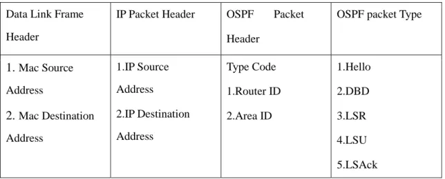
3.2 OSPF Message Encapsulation
OSPF message is encapsulated in a packet. Table 3.1 lists the encapsulated OSPF message [4].
Table 3.1: Encapsulated OSPF Message
Data Link Frame Header
IP Packet Header OSPF Packet Header
OSPF packet Type
1. Mac Source Address
2. Mac Destination Address
1.IP Source Address
2.IP Destination Address
Type Code 1.Router ID 2.Area ID
1.Hello 2.DBD 3.LSR 4.LSU 5.LSAck
3.3 OSPF Packet Header
OSPF packets composed of nine fields. As demonstrated in table 3.2.
© Daffodil International University Page 14 Table 3.2: Packet Format
Version Type
Router ID Area ID
Checksum AuType
Authentication Authentication
Each field is defined as following:
3.3.1 Version:
Types of OSPF version used3.3.2 Type:
Indicates OSPF packet type as follow:
Hello.
Database Description (DBD).
Link State Request (LSR).
Link State Update (LSU).
Link State Acknowledgement (LSAck).
3.3.3 Router ID:
Identifies ID of the source router.3.3.4 Area ID:
ID of the area to which packets belong.3.3.5 Checksum:
To check packets that are damaged or not damaged during transmission.3.3.6 Au Type:
Defines authentication type. Three type of authentication exist:
0- It means the routing information that is exchanged over the network is not authenticated.
1- Simple authentication allows a password.
© Daffodil International University Page 15 2- Message digest authentication allows a cryptographic authentication.
3.3.7 Authentication:
To authenticate OSPF packets such that router is able to participate in the routing domain.
3.4 OSPF Packet Types
There are five different types of OSPF packets in which each packet has a specific purpose in OSPF process that are briefly described below:
1. Hello:
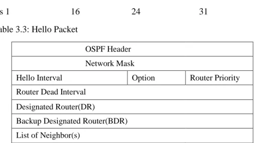
Hello packets are used to discover neighbor and establish adjacency with other OSPF routers. To make adjacency neighbors, routers must agree to be neighbors with each other. Hello packets prefer the Designated Router (DR) as well as Backup Designated Router (BDR) on multi access networks.Table 3.3 shows the Hello packet formation:
Bits 1 16 24 31 Table 3.3: Hello Packet
OSPF Header Network Mask
Hello Interval Option Router Priority
Router Dead Interval Designated Router(DR)
Backup Designated Router(BDR) List of Neighbor(s)
1.1 Network Mask:
This field consists of 32 bits indicating that subnet mask is associated with the sending interface.© Daffodil International University Page 16
1.2 Hello Interval:
Interval between sending routers that is measured by number of seconds to form adjacency. The Hello interval is 10 seconds for point to point and 30 seconds for broadcast media. It must be same for both routers.
1.3 Option:
This field is defined for optional capability to support OSPF router in future.
1.4 Router Priority:
Router priority is used in DR/BDR. If priority is set to 1, DR is elected as a higher priority router.
1.5 Router Dead Interval:
Specifies the time interval to notify a neighbor as dead. Dead interval is traced to 4 times the Hello interval by default.
1.6 Designated Router:
Router ID is set to DR. If no router ID is defined, there is no DR defined in the network.
1.7 Backup Designated Router:
One router is elected as a BDR in the network. If the router ID is 0, no BDR exists in the network.
1.8 List of Neighbors:
To figure out the lists, the OSPF router IDs of the neighboring routers.
2. Database Description:
The database description (DBD) packet keeps the list of the sending routers link state database abbreviated and is used by receiving routers to verify against the local link state database.
3. Link State Request Packet:
Having exchanged database description packets with neighboring routers, receiving routers can then request to know more information about any entry in© Daffodil International University Page 17 the DBD by sending link state request (LSR).
4. Link State Update:
Link state update is used to flood the link state advertisement to LSR. Seven different types of LSA are used in LSU.
5. Link State Acknowledgement Packet:
Router sends a link state acknowledgement to confirm the sender as LSU is received reliably.
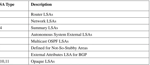
Different LSAs are shown in table 3.4:
Table 3.4: Different LSAs
LSA Type Description
1 Router LSAs
2 Network LSAs
3,4 Summary LSAs
5 Autonomous System External LSAs
6 Multicast OSPF LSAs
7 Defined for Not-So-Stubby Areas 8 External Attributes LSA for BGP 9,10,11 Opaque LSAs
3.5 OSPF Area
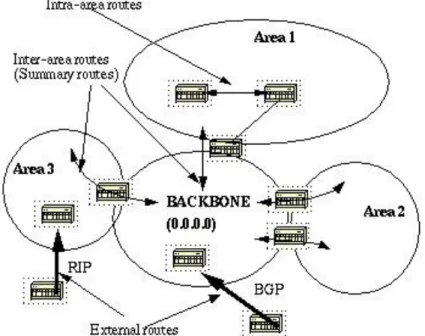
OSPF areas are applied to build a hierarchical structure to maintain a flow of data packet in the network. OSPF will have at least one area in the network. If more than one area exists in the network, one of the areas must be a backbone area which is to be connected to all other areas. Areas are used to group of routers to exchange routing information locally. An area can be implemented in two ways:
one is IP address format 0.0.0.0 and another is in decimal format 0. Backbone area is referred to the decimal number 0 or IP address 0.0.0.0. If any area is not connected to backbone directly, a virtual link would be needed. Area can be configured in several types that depend on the network requirements [12].
© Daffodil International University Page 18
3.5.1 Backbone Area
When designing a network, if one or more area is considered, one of the areas must be a backbone area 0. All areas will have to be directly connected to backbone area. Backbone area has to be at the centre of all areas so that all areas introduce routing information into the backbone and consequently, backbone distributes information to other areas. Figure 3.1 depicts backbone area has connection to all other areas [14].
Figure 3.1: Backbone Area
3.6 OSPF Cost
The path cost of an interface in OSPF is called metric that indicates standard value such as speed. The cost of an interface is calculated on the basis of bandwidth. Cost is inversely proportional to the bandwidth. Higher bandwidth is attained with a lower cost [4].
Where the value of 10଼ is 100000000 in bps is called reference bandwidth based on by default.
© Daffodil International University Page 19 From the formula, it can be seen that cost would be found if reference bandwidth is divided by interface bandwidth.
3.7 OSPF Router Types
OSPF routers play a various roles in the network where they are placed and the areas in which they are positioned.
Different types of OSPF routers are defined as follows [15].
Internal routers:
Router that connects only one OSPF area is called internal router. All of its interfaces have connection within the same area. OSPF algorithm is run into IR.Backbone routers:
Routers that have more than one interfaces in area 0 is called backbone area.Backbone routers can be considered as an ABR routers and internal routers.
Area border routers:
A router that connects multiple areas is called ABR.ABR is used to link at non backbone areas to the backbone. Summary link advertisement is generated by ABR.
Autonomous system boundary routers:
If a router which belong toOSPF area and has a connection to another OSPF area is called an ASBR. It acts like a gateway.
Designated routers:
A router at which all other routers have connection within an area and send Link State Advertisement is called DR. Designated routers keep all their Link State Updates and flood LSAs to other networks reliably. Every OSPF can have a DR and a Backup Designated Router (BDR). DR must have higher priority in the OSPF area.© Daffodil International University Page 20
3.8 OSPF and Route Summarization
Multiple routes are summarized into one single route. This summarization is done by ABRs. This process is used to merge up the list of multiple routes into one route. Summarization can be done by considering between any two areas. It reduces routing table overhead and the network size. The main purpose of summarization is to reduce the bandwidth and processing time. There are two types of route summarization which can be performed in OSPF. These are briefly described below:
1. Inter-Area Route Summarization:
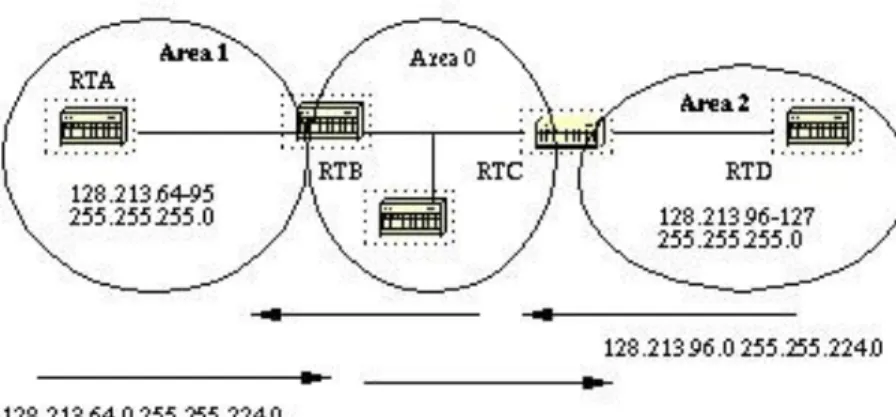
The process of inter-area route summarization is done by ABRs to concern route in the Autonomous System. External routes are not injected into OSPF through redistribution. An example of summarization is shown in figure 3.2[14].
Figure 3.2: Inter-area-route summarization
Figure 3.4 shows that router RTB act as an ABR. RTB router is summarizing the subnet address from 128.213.64.0 to 128.213.95.0 into single range: 128.213.64.0 255.255.224.0 achieved by masking. In the same manner, RTC router is summarizing the subnet address from 128.213.96 to 127 into backbone providing a range 128.213.96.0 255.255.224.0.
2. External Route Summarization:
External route summarization allowsexternal routes to inject into OSPF via redistribution. The external ranges that are being summarized must be contiguous. The procedure of injecting between two routers is figured out below [14].
© Daffodil International University Page 21 Figure 3.3: External route summarization
In the above diagram, it can be seen that there are two external routes that are injecting by RTA and RTD routers through redistribution. RTA router is summarizing address from 128.213.64-95 and RTD from 128.213.96-127. These addresses are summarized into one range: 128.213.65.0 255.255.224.0 for RTA and 128.213.96.0 255.255.224.0 for RTD.
3.9 Link State Advertisement (LSA)
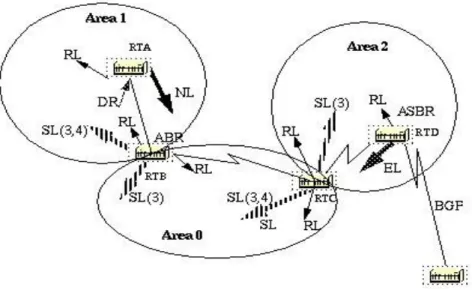
Link State Advertisement is divided into five parts.
These are:
Type1. Router Link (RL):
Generally router links are generated by all routers. It describes the state of the router interfaces for each area where it belongs to. LSAs are flooded within the routers area.
Type2. Network Link (NL):
Designated Router (DR) is responsible for generating network links to explain a set of routers connected a particular network.Network links are flooded to the area.
Type3/4. Summary Links (SL):
Summary links are generated by ABRs defining inter- area route. Summary links keep lists of other areas in the network belonging to the autonomous system.ABRs inject summary link from the backbone to other areas and other areas to the backbone.
© Daffodil International University Page 22 Backbone aggregates address between areas by summary link. Another type of summary links is generated by ASBRs. All routers in the network know the way to external route the AS.
Type5. External Links (EL):
ASBRs injects external routes viaredistribution to the autonomous system. This link is flooded to all areas but stub area.
Figure 3.4 illustrates the different types of LSAs [14].
Figure 3.4: Different types of link state advertisements
3.10 Shortest Path First (SPF) Algorithm
OSPF is a link state routing protocol which uses a shortest path first algorithm to calculate the least cost path to all known destinations. Dijkstra algorithm is used for calculating the shortest path.
Several procedures of this algorithm are given below:
Any changes in the routing information, a link state advertisement is generated by a router. This advertisement provides all link states on that router.
© Daffodil International University Page 23 All routers exchange LSAs by flooding. Then link state update is received by each router and
preserves a copy of link state database in it. This link state update propagates to all other routers.
After creation of database of each router, routers start calculating shortest path tree to the destinations. In order to find the least cost path, router uses Dijkstra algorithm.
If any changes occurred in the OSPF network such as link cost, new network being added or deleted, Dijkstra algorithm is recalculated to find the least cost path.
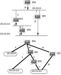
Every router uses this algorithm at the root of the tree in order to find the shortest path on the basis of cost to reach the destinations. In figure 3.5 shows that a network diagram that is indicated with the interface cost to find out the shortest path [14].
Figure 3.5: Shortest Path Tree
3.11 OSPF Convergence
Consider the network in Figure 3.8 running OSPF. Assume the link between R3 and R5 fails. R3 detects link failure and sends LSA to R2 and R4. Since a change in the network is detected traffic forwarding is suspended. R2and R4 updates their topology database, copies the LSA and flood their neighbors.
© Daffodil International University Page 24 Figure 3.8: OSPF Network
By flooding LSA all the devices in the network have topological awareness. A new routing table is generated by all the routers by running Dijkstra algorithm. The traffic is now forwarded via R4.
3.12 Advantages and Disadvantages of OSPF
The advantages of OSPF are:
OSPF is not a Cisco proprietary protocol.
OSPF always determine the loop free routes.
If any changes occur in the network it updates fast.
OSPF minimizes the routes and reduces the size of routing table by configuring area.
Low bandwidth utilization.
Multiple routes are supported.
OSPF is based on cost.
Support variable length subnet masking.
It is suitable for large network.
© Daffodil International University Page 25 Disadvantages of OSPF are:
Difficult to configure.
Link state scaling problem.
More memory requirements. To keep information of all areas and networks connected within an area OSPF utilizes link-state databases. If the topology is complex, LSDB may become outsized which may reduce of the maximum size of an area.
© Daffodil International University Page 26
CHAPTER 4:
ENHANCED INTERIOR GATEWAY ROUTING PROTOCOL
4.1 Introduction
Enhanced Interior Gateway Routing Protocol (EIGRP) is a CISCO proprietary protocol, which is an improved version of the interior gateway routing protocol (IGRP). EIGRP is being used as a more scalable protocol in both medium and large scale networks since 1992. EIGRP is said to be an extensively used IGRP where route computation is done through Diffusion Update Algorithm (DUAL). However, EIGRP can also be considered as hybrid protocol because of having link state protocol properties.
4.2 Protocol Structure
Table 4.1: Protocol structure of EIGRP
Bits 1 8 16 31
Version Opcode Checksum Flags
Sequence Number Acknowledge Number Autonomous System Number
Type Length
Table 4.1 demonstrates the protocol structure of EIGRP and each field is shortly described [17] below:
Version:
Indicates the version of EIGRPOpcode:
The Operat io n code usually spec ifies t he me ssa g et ypes. For example: 1. Update, 2. Reserved, 3. Query, 4. Reply, 5. HELLO, 6. IPX-SAP.
Checksum:
Identifies IP checksum that is calculated by using the same checksum algorithm.© Daffodil International University Page 27
Flag:
First bit (0x00000001) is used to form a new neighbor relationship and is known as initialization bit. Second bit (0x00000002) is used in proprietary multicast algorithm and is termed as conditional receive bit. There is no function for the remaining bits.Sequence a nd Ac knowle d ge N umbe r :
Passing m e s s a g e s s e c u r e l y a nd reliably.
Autonomous System:
It explains the independent system numbers which is found in EIGRP domain. The separate routing tables are found to be associated with each AS because a gateway can be used in more than one AS. This field is used for specifying the exact routing table.
Type:
Determine the type field values which are:- 0x0001-EIGRP Parameters (Hello/Hold time) - 0x0002-Reserved
- 0x0003-Sequence
- 0x0004-Software Version of EIGRP - 0x0005-Next Multicast Sequence - 0x0012-IP Internal Routes
- 0x0013-IP External Routes
Length:
Describes the length of the frame.
4.3 Method of EIGRP
EIGRP has four methods. They are:
i. Neighbor Discovery/Recovery ii. Reliable Transport Protocol (RTP) iii. Diffusion Update Algorithm (DUAL) iv. Protocol Dependent Modules (PDM)
© Daffodil International University Page 28
4.3.1 Neighbor Discovery/Recovery
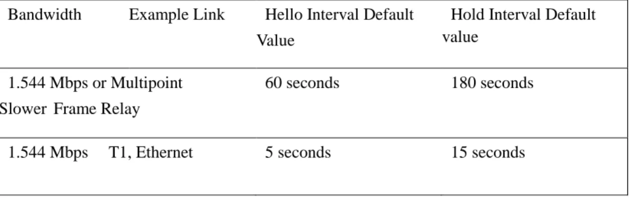
The neighbor discovery/recovery method allows the routers to gain knowledge about other routers which are directly linked to their networks [18] [19]. If the neighbors become unreachable, it is very important for them to be able to discover it. This is done by sending HELLO packets at intervals with a comparatively low overhead. After receiving a HELLO packet from its neighbors, the router ensures that its neighboring routers are okay and the exchange of routing information is possible. In case of high speed networks, t he default value for HELLO time is 5 seconds. Every HELLO packet advertises the holding time for maintaining the relationship. Hold time can be defined as the particular time when the neighbor judges the sender as alive. The default value of hold time is 15 seconds. If the EIGRP router does not accept any HELLO packets from the adjacent router during the hold time interval, the adjacent router is removed from the routing table. Therefore, hold time is not only to be used for detecting the loss of neighbors but also for discovering neighbors. On multipoint interfaces, HELLO/Hold time for networks with link speed T-1 is usually set to 60/180 seconds. The convergence time lengthened with the extension of the HELLO interval time. Nevertheless, HELLO intervals with long duration are possible to be implemented in congested networks of several EIGRP routers.
In a network, the HELLO/Hold time differs among the routers. A rule of thumb states that the hold time should be equal to thrice of the HELLO time [21]. Table 3.1 presents the default values of HELLO and hold times for EIGRP [4].
Table 4.2: EIGRP interval time for Hello and Hold
Bandwidth Example Link Hello Interval Default Value
Hold Interval Default value
1.544 Mbps or Multipoint Slower Frame Relay
60 seconds 180 seconds
1.544 Mbps T1, Ethernet 5 seconds 15 seconds
© Daffodil International University Page 29
4.3.2 Reliable Transport Protocol
The sequence number is used to make the sorting in series for the routing updates information. RTP allows intermixed transmission of multicast or uncast packets. The certain EIGRP packets need to be transmitted reliably while others do not require. Hence reliability can be ensured according to the requirement. For instance, in case of Ethernet, which is a multi access network and provide multicasting capacity, it is not vital to transmit HELLOs reliably to other neighbors.
Thus, by sending a single multicast HELLO, EIGRP informs receivers, that the packets are not needed to be acknowledged. But updating packets need to be acknowledged when they are sent. RTP has a condition to transmit the multicast packet very fast when there are some unacknowledged packets left.
For this reason, in the presence of varying speed links, this helps to ensure that the convergence time are low.
4.3.3 Diffusion Update Algorithm
The Diffusion Update Algorithm (DUAL) uses some provisions and theories which has a significant role in loop-avoidance mechanism as follows:
Feasible Distance (FD)
The lowest cost needed to reach the destination is usually termed as the feasible Distance for that specific destination.
Reported Distance (RD)
A router has a cost for reaching the destination and it is denoted as reported distance.
Successor
A successor is basically an adjacent router which determines the least-cost route to the destination network.
Feasible Successor (FS)
FS is an adjacent router which is used to offer a loop free backup path to the destination by fulfilling the conditions of FC.
© Daffodil International University Page 30
Feasible Condition (FC)
After the condition of FD is met, FC is used in order to select the reasonable successor. The RD advertised by a router should be less than the FD to the same destination for fulfilling the condition.
In EIGRP, all route calculations are taken care by the DUAL. One of the tasks of DUAL comprises keeping a table, known as topology table, which includes all the entries found from the loop-free paths advertised by all routers. DUAL selects the best loop-free path (known as successor path) and second best loop free path (known as feasible path) from the topology table by using the distance information and then save this into the routing table. The neighbor of the least cost route to the destination is called a successor.
By using the topology table, DUAL can check if another best loop-free path is available. DUAL performs this when the successor path is unreachable. This path is recognized as feasible path. The reasonable path is selected if it satisfies the FC. The FC condition is possible to be satisfied if the neighbor's RD to a network is less than the RD of the local router. When a neighbor router meets the FC condition, it is then termed as FS.
In case of having no loop-free path in the topology table, re-calculation of the route must take place and then the DUAL inquire its neighbors [21]. This occurs during recalculation for searching a new successor. Although, the re-calculation of the route does not seem to be processor-intensive, it may have an effect on the convergence time and consequently, it is useful for avoiding needless computations [18][19][22]. In case of having any FS, DUAL is used for avoiding any needless re- computation. If we consider Figure 4.1, we will be able to understand how the DUAL converges. This example aims at router K for the destination only. The cost of K (hops) coming from each router is presented below [19]:
© Daffodil International University Page 31
Figure 4.1: DUAL placed in the network
In Figure 4.2 [3], the link from A to D fails. When the loss of the FS occurs, a message goes to the adjacent router sent by D. This is received by C. Then C determines if there is any FS. In case of having no FS, C needs to begin a new route calculation by entering the active state. The cost from router C to router K is 3 and the cost from router B to router K is 2. Hence it is possible for C to switch to B. There is no effect on router A and B for this change. Thus they have no contribution in finding the reasonable successor.
Figure 4.2: Failure Link of Network Topology
© Daffodil International University Page 32 Now, observe the case in figure 4.3 [3], where the link from A to B fails. B is found in this scenario to have been lost its successor and thus no FS exists. Router C cannot be treated as FS to B, as the cost of C is more than the present cost of B. Consequently, the route computation is to be performed by B and for this, B sends a query to its neighbor C. In reply, C acknowledges the query because C does not need to perform the route calculation.
When B receives the reply, it assumes that all the adjacent routers have processed the link failure. B can choose C for getting the destinations as its successor with a cost of 4. It didn’t have any effect on A and D for changing the topology and thus, C needed just to reply on B.
Figure 4.3: Failure Link of Network Topology
4.4 EIGRP Metrics
With the use of total delay and the minimum link bandwidth, it is possible to determine the routing metrics in EIGRP. Composite metrics, which consists of bandwidth, reliability, delay, and load, are considered to be used for the purpose of calculating the preferred path to the networks. The EIGRP routing update takes the hop count into account though EIGRP does not include hop count as a component of composite metrics. The total delay and the minimum bandwidth metrics can be achieved
© Daffodil International University Page 33 from values which are put together on interfaces and the formula used to compute the metric is followed by:
4.5 EIGRP Convergence
We assume in figure 4.4, that the link from R3 and R5 goes down and at the same time R3 identifies the failure of the link. There is no FS present in the topology database and hence the role of R3 is to be entered into the active convergence. R4 and R2, on the other hand, are the only neighbors to R3.
Given that, there is no availability of route with lower FD; R3 sends a message to both R4 and R2 for gaining a logical successor. R2, for acknowledgement, replies to R3 and indicates that there is no availability of successor. On the other hand, R3 gets positive acknowledgement from R4 and the FS with higher FD becomes available to R3. The distance and new path is allowed by R3 and then added
© Daffodil International University Page 34 to the routing table. Followed by R2 and R4 are sent an update about the higher metric. In the network, all the routes converge when the updates are reached to them.
Figure 4.4: Network topology of EIGRP
4.6 Advantages and Disadvantages of EIGRP
There are some advantages provides by EIGRP as follows:
Easy to configure.
Loop free routes are offered.
It keeps a back up path in the network to get the destination.
Multiple network layer protocols are included.
EIGRP convergence time is low and it is responsible for the reduction of the bandwidth utilization.
It can work with Variable Length Subnet Mask (VLSM) and Class Less Inter Domain Routing (CIDR).
EIGRP also supports the routing update authentication.
© Daffodil International University Page 35 Disadvantages of EIGRP are:
Considered as Cisco proprietary routing protocol.
Routers from other vendors are not able to utilize EIGRP.
CHAPTER 5:
SIMULATION & RESULTS
5.1 Introduction
Simulation can be defined to show the eventual real behavior of the selected system model .It is used for performance optimization on the basis of creating a model of the system in order to gain insight
© Daffodil International University Page 36 into their functioning. We can predict the estimation and assumption of the real system by using simulation results.
5.2 Simulator
In this thesis, network simulator, Optimized Network Engineering Tools (OPNET) modeler 14.0 has been used as a simulation environment. OPNET is a simulator built on top of discrete event system (DES) and it simulates the system behavior by modeling each event in the system and processes it through user defined processes. OPNET is very powerful software to simulate heterogeneous network with various protocols.
5.3 Design and Analysis in OPNET
When implementing a real model of the system in the OPNET, some steps are to be followed to design on simulator. Figure 5.1 shows a flow chart of the steps [3].
Figure 5.1: Designing Steps
5.4 Simulation Study
The protocols used in this thesis are OSPF and EIGRP routing protocol. The proposed routing protocols are compared and evaluated based on some quantitative metrics such as convergence duration, packet delay variation, end to end delay, jitter and throughput. These protocols are intended to use to get better performance of one over the other for real time traffic such as video streaming and voice conferencing in the entire network.
© Daffodil International University Page 37
5.5 Network Topology
Figure 5.2: Network Topology
In this thesis, three scenarios are created that consists of six interconnected subnets where routers within each subnet are configured by using EIGRP and OSPF routing protocols. The network topology composed of the following network devices and
configuration utilities:
CS_7000 Cisco Routers Ethernet Server
Switch
PPP_DS3 Duplex Link PPP_DS1 Duplex Link
Ethernet 10 BaseT Duplex Link Ethernet Workstation
Six Subnets
Application Configuration
© Daffodil International University Page 38 Profile Configuration
Failure Recovery Configuration QoS Attribute Configuration
The network topology design is based on the geographical layout of Bangladesh shown below in figure 5.3. We considered six subnets in accordance with the name o f division in Bangladesh that are interconnected to each other. All of the subnets contain routers, switch and workstations. Internal infrastructure of the network topology is shown in figure 5.3
Figure 5.3: Internal Infrastructure of Network Topology
An Application Definition Object and a Profile Definition Object named correspondingly Application Config and Profile Config in the figure 5.2 are added from the object palette into the workspace. The Application Config allows generating different types of application traffic. As far as real time applications are concerned in our thesis work, the Application Definition Object is set to support Video Streaming (Light) and Voice Conferencing (PCM Quality). A Profile Definition Object defines the profiles within the defined application traffic of the Application Definition Objects. In the Profile
© Daffodil International University Page 39 Config, two profiles are created. One of the Profiles has the application support of Video Streaming (Light) and another one has Voice Conferencing (PCM Quality) support.
Failure link has been configured in the scenarios. Failure events introduce disturbances in the routing topology, leading to additional intervals of convergence activity. The link connected between Sylhet and Barishal is set to be failure for 300 seconds and recovered after 500 seconds. One Video Server is connected to Dhaka Router that is set to the Video Streaming under the supported services of the Video Server. Quality of Service (QoS) plays an important role to achieve the guaranteed data rate and latency over the network. In order to implement QoS, IP QoS Object called QoS Parameters in the workspace where it has been used to enable and deploy Weighted Fair Queuing (WFQ). WFQ is a scheduling technique that allows different scheduling priorities on the basis of Type of Service (ToS) and Differentiated Service Code Point (DSCP).
The routers are connected using PPP_DS3 duplex link with each other. The switches are connected to routers using same duplex link. Ethernet workstations are co nnected to switch using 10 BaseT duplex links.
5.6 EIGRP Scenario
In this scenario, EIGRP routing protocol is enabled first for all routers on the network. After configuring routing protocols, individual DES statistics was chosen to select performance metrics and to measure the behavior of this routing protocol. Then simulation run time was set to 15 minutes.