We hereby solemnly declare that the work presented here in this project report on IOT based fire detection robot has been done by us and has not been previously submitted to any university/organization for awarding any degree or certificate. We further undertake to indemnify the University against any loss or damage arising from a breach of the above obligation. Mostof Hossain, Head of the Department of Mechanical Engineering and all respected teachers of the Department of Mechanical Engineering for their cooperation and important help in the successful completion of the thesis.
IOT Based Fire Detection Robot” are automatic robots which are able to receive a set of command instructions in the form of internet service and perform the necessary actions. The robot itself and send the data using internet service according to the necessary actions. The microcontroller is also connected with few DC gear motors to move the robot in different directions.
The ON and OFF of the DC motors depends on the direction it needs to move, which is the entire responsibility of the controller to make those intelligent decisions. The aim of this project is to enable the robot to function in unstructured and dynamic environments and perform multiple tasks such as sensing changes in the environment and providing countermeasures, observing the surrounding activities through an ultrasonic sensor.
Overall aim of the project (Enumerated)
Motivation
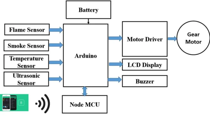
SYSTEM ARCHITECTURE
Block Diagram
Working Principle
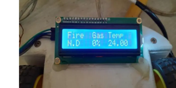
There is an LCD display on the car, so we can also see the condition of the car and other warnings.
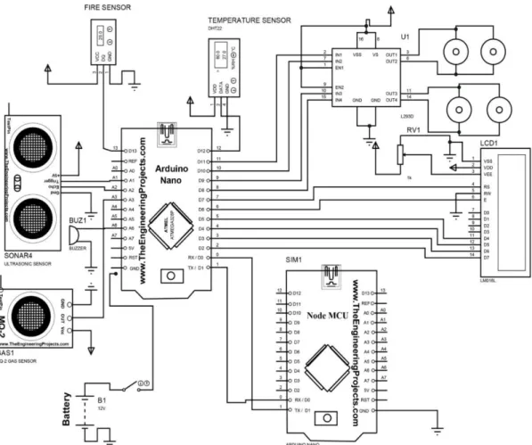
Methodology
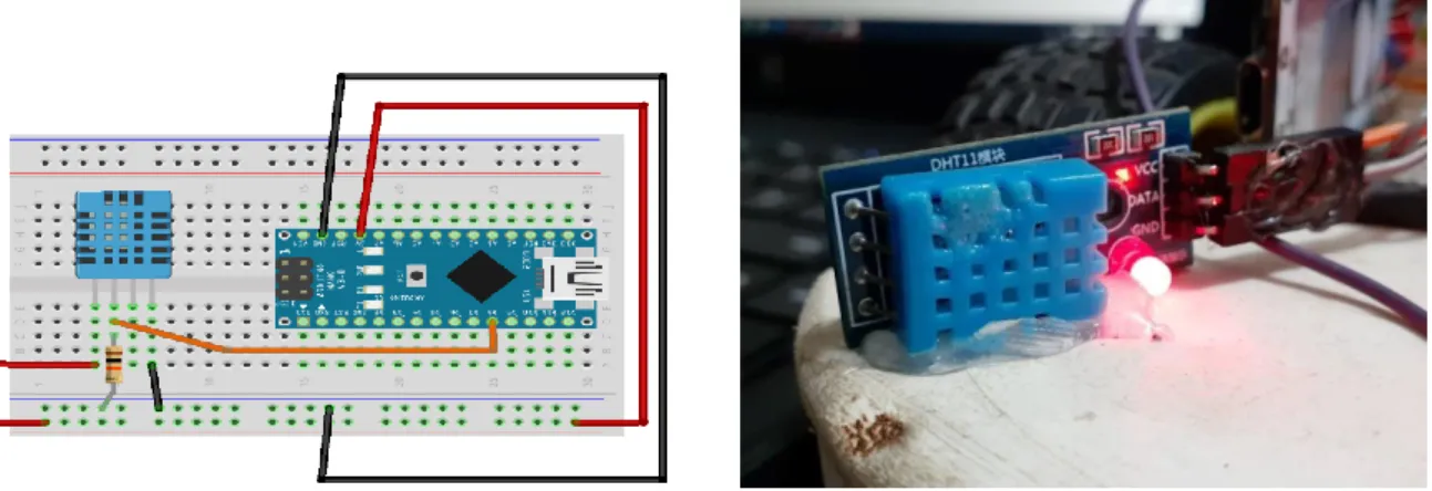
- Connecting the temperature sensor DHT 11 to Arduino
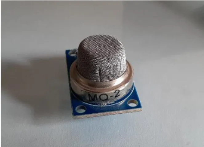
- Connecting the gas sensor MQ-2 to Arduino
- Connecting ultrasonic sensor HC-SR04 Arduino
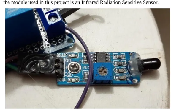
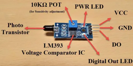
- Connecting the fire sensor LM-393 to Arduino
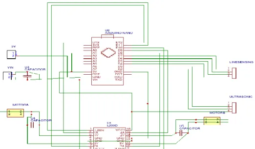
- Connecting Motor controller to Arduino
- Connecting the NodeMCU to Arduino
- Construction of 4-wheel Chassis and connect with Arduino Hardware Required
- Connecting Buzzer to Arduino
- Connecting the Relay to Arduino
- Connecting voltage regulator 7805 and 7806 to Arduino
The Vcc pin is connected back to the 5V power pin and the Gnd pin to Arduino's Gnd pin. So we will connect this pin to one of the analog pins of Arduino like A0. Connect VCC and GND to +5V and GND of the power supply (can be connected to Arduino's +5V).
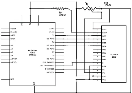
Before we wire the LCD screen to the Arduino board, we need to solder a pin header strip to the 16-pin count connector of the LCD screen. Place the L293D in the middle of the breadboard, with half of the pins on either side of the breadboard. We are going to use the motor drivers because Arduino Uno does not provide enough power to run 4 Motors.
The Buzzer and LEDs are placed on the breadboard and all their negative terminals are connected to the Arduino Gnd pin. The respective positive pins are connected to the individual digital pins on the Arduino nano.
IOT BASED FIRE DETECTION ROBOT
HARDWARE ANALYSIS
- Arduino Nano
- LCD Display
- Motor Driver
- Ultrasonic Sensor
- DHT11 Temperature Sensor
- Flame Sensor
- Node MCU
- Smoke Sensor
- Buzzer
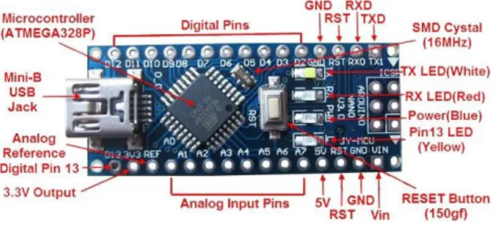
The Nano has the capability to accommodate Arduino and Mini+USB with a smaller footprint than both, giving users more space on the navigation board. Almost all types of DC motors have some internal mechanism, electromechanical or electronic, to periodically change the direction of the current in the motor section. A coil of wire with a current flowing through it creates an electromagnetic field that is aligned with the center of the coil.
The direction and magnitude of the magnetic field produced by the coil can be changed by the direction and magnitude of the current flowing through it. The total amount of current sent into the coil, the size of the coil and around which it is wrapped dictate the strength of the electromagnetic field created. Due to its size, it is very widely used in robotic application for controlling DC motors.
If any of pins 1 or 9 goes down, the motor in the corresponding section will suspend operation. The left input pins will adjust the rotation of the motor connected to the left side and the right input for the motor on the right side. The motors rotate based on inputs given through input pins such as LOGIC 0 or LOGIC 1.
In simple you need to provide Logic 0 or 1 across the input pins to turn the motor. In a very similar way, the motor can also operate via input pin 15,10 for motor on the right side. The circuits built into the module will calculate the time it takes for the US wave to come back and turn the echo pin high for the same specific time, this way we can also know the time it takes.
It includes firmware running on the ESP8266 Wi-Fi SoC from Espressif Systems, and hardware based on the ESP-12 module. It is based on the eLua project, and built on the Espressif Non-OS SDK for ESP8266. The output is an analog signal and can be read with an analog input from the Arduino.
3.11 5V Relay
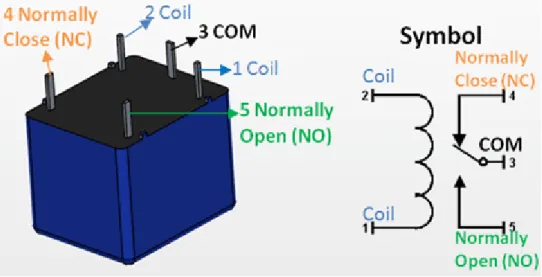
A piezo buzzer is connected to a digital output that beeps when the output is high. When the piezo buzzer is connected to the analog pulse modulation output, it produces a variety of tones and effects. Since the relay has a 5 V trigger voltage, we used a +5 V DC supply on one end of the coil and the other end to ground via a switch.
This switch can be anything from a small transistor to a microcontroller or a microprocessor that can perform switching. You can also see a diode connected across the coil of the relay, this diode is called the Fly Back Diode. The purpose of the diode is to protect the switch from a high voltage spike that can be produced by the relay coil.
As shown, one end of the load can be connected to the common pin and the other end connected to either NO or NC. If connected to NO, the load remains disconnected before switching on and if connected to NC the load remains connected before switching on.
SOFTWARE DESCRIPTION
Arduino software
This also provides power to the board, as indicated by the blue LED (which is on the bottom of the Arduino Nano 2.x and the top of the Arduino Nano 3.0). You must select the entry in the Tools > Board menu that corresponds to your Nano board. Boards sold from us from January 2018 have this new bootloader, while boards manufactured before that date have the old bootloader.
First, make sure you have Arduino AVR Core 1.16.21 or later, which you can view in Board Manager. If you get an error while booting or you're not sure which bootloader you have, try each type of 328P processor until your board is programmed correctly. Wait a few seconds - you should see the RX and TX lights on the board flashing.
If the upload is successful, the message "Upload complete." is displayed in the status bar.
Blynk App
The Auth Token is very important - you will need to insert it into the firmware of your ESP8266. For now, copy it or use the "Email" button to send it to yourself. Now that your Blynk project is set up, open Arduino and navigate to the ESP8266_Standalone example in File > Examples > Blynk > WiFi_Boards>.
Also, make sure you load your Wifi settings into the Blynk.begin(auth, “ssid”, “pass”) function. After entering our code into the Node MCU, it will be able to connect to the Blynk app.
Result and Analysis
- Overview
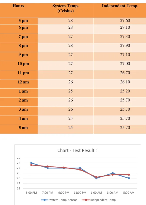
- Temperature, Gas and Fire Detection Tests
- Temperature Monitoring
- Fire Detection Test
- Detecting Obstacle
- Result Analysis
The test started at 17:00 in the evening and ended at 5 in the morning. The test unit simulates the burning flame signal by modulating the output of a lighter or filament lamp. The sensor is interfaced to the microcontroller with one output as a trigger and the other input as an echo.
If the echo signal with a high width is detected in the predefined area, then the obstacle is taken into account, and at the same time the motor driver IC L293D is commanded to LOW (motor 2 and 3), then it turns right and finds another way forward. At any time when an obstacle is found in the range of ultrasonic sensors, the firmware activated L293D. The ultrasonic detector HC-SR04 circuit is a circuit that gives a low output in the absence of an ultrasonic signal when an obstacle comes in the way. The ultrasound signal is reflected back and falls on the ultrasound detector. After analyzing the test results, the following conclusion can be drawn: 1) The temperature was measured and the error is within the tolerance limit.
FUTURE RECOMMENDATION
Future Improvements and Applications
Discussion
- Discussion
PROJECT TIME ALLOCATION
In this IOT based fire detection robot project we have completed successfully and the test results of this project are quite good nowadays robotics technology is becoming more and more efficient to complete our daily task. We tried to make a tool on robotics that can help us or can give us some ideas to implement or improve our goals. As this project can help in fire and gas leak detection, so this type of robot can be used for home and also in defense area with some modifications.
Local Control Sketch for Arduino Nano (local.ino)
Local Control Sketch for Node MCU (local_mcu.ino)
The first thing we need to do is we need to put the user's hotspot or if the user is using WiFi, the WiFi name and password into the robots Node MCU. Then to connect this robot to the phone, we need to enable hotspot and mobile data/wifi and location. After connecting to the robot via Blynk, you can turn the robot on and off with Blynk and the output of some sensors will be visible in the Blynk home screen.