Artificial intelligence is a collaborator in a completely fascinating field of nursing that interests most of the people. This project is provided with DC motor, voice recognition module, microcontroller at the facility offering unit side.
INTRODUCTION…………………… (3-5)
- AIM OF THE PROJECT
- SCOPES
- METHODOLOGY
- ORGANIZATION OF THE REPORT
This system is used to control all the robot hardware connected to the microcontroller. Chapter 3 on component description, cost analysis of our system. Chapter 4 software analysis & program explanation.
SYSTEM REVIEW……………………. (6-10)
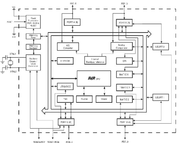
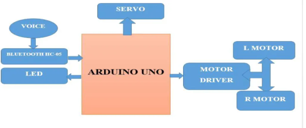
BLOCK DIAGRAM
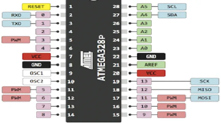
- PIN DESCRIPTION
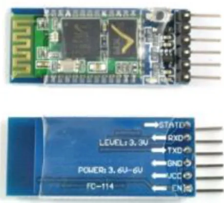
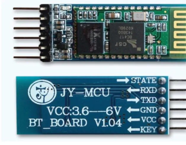
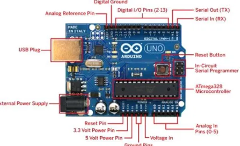
Usage The microcontroller on these boards is programmed to behave in the Arduino programming language (Wiring-based) and the Arduino development environment (Processing-based). The Arduino Uno is a microcontroller board based on the ATmega328. At the time when the shift buttons are pressed, these specific commands are passed by the voice applications and this is the command, we get an execution output for the bot. The arduino software that detects that the signal has been sent and compares it to the default signal to set for the entire application. Nowadays there are many types of wireless connectivity such as Wi-Fi, cellular data, Zigbee and the most popular and widely used wireless protocols using bluetooth. Bluetooth standard 5 was announced in 2016 and looking for Bluetooth 4.2 standard is usually used this moment.
Because the Android platform is built for mobile devices, a typical Android application is designed for a smartphone or a tablet computer running the Android operating system. Although an Android app is often marketed by developers through their websites, most Android apps are uploaded and published on the Android Market, an Internet store dedicated to those apps. They are 1st compiled to Dalvik which is feasible to run on the Dalvik virtual machine, which can be a virtual machine specially designed for mobile devices.
Each of the 14 digital pins on the Mega can be used as an input or output using the pin Mode, digitalWrite and digitalRead functions. Usually used to add a reset button to shields that block the one on the board.
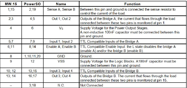
L298N MOTOR DRIVER
- L298N CONNECTIONS
- VOLTAGE SPECIFICATION
Each pin can supply or receive a maximum of 40 mA and has an internal pull-up resistor (disabled by default) of 20-50 kohm. These pins are connected to the corresponding pins of the ATmega8U2 USB-to-TTL serial chip. These pins can be configured to trigger an interrupt on a low value, a rising or falling edge, or a value change.
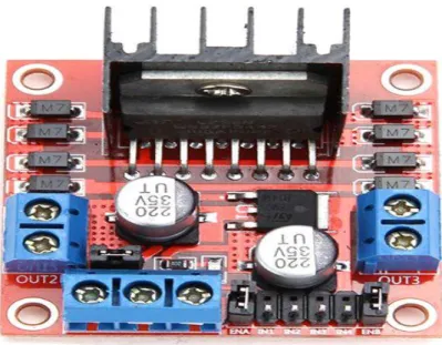
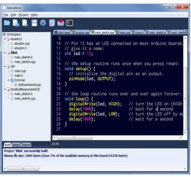
When the pin is HIGH, the LED is on, when the pin is LOW, it is off. Memory: The Atmega 328 has 32 Kb of flash memory for storing code of which 0.5 KB is used for the bootloader and 2 KB of SRAM and 1 KB of EEPROM, which are also read and written with the EEPROM library. Similarly, when the enable input is low, that driver is disabled and their outputs are off and in a high-impedance state.
If we see the L298N motor driver pins and we need to understand the functionality of each pin before implementing this in a circuit.
DESCRIPTION OF LCD DISPLAY16x2
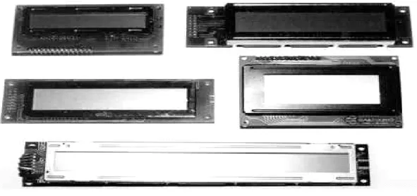
- SHAPES AND SIZES
- PIN DESCRIPTION
- CONTROL LINES
- INITIALLIZATION BY INSTRUCTIONS…
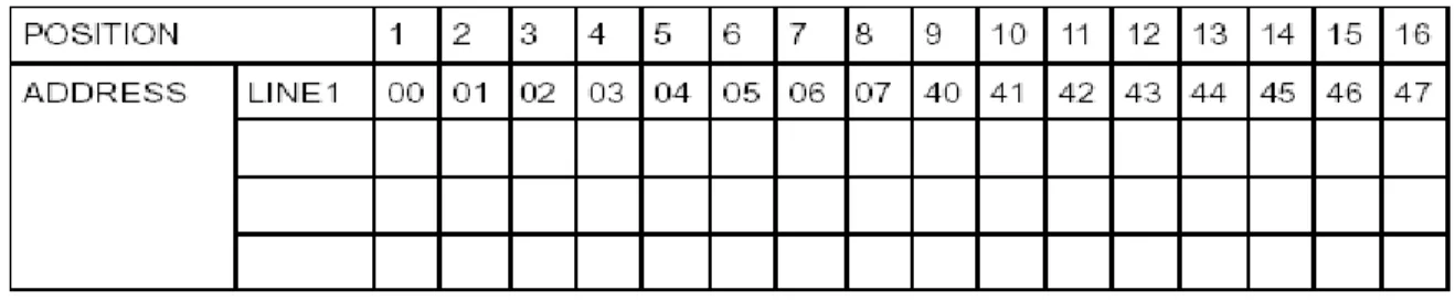
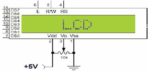
Supertwist types, for example, offer improved contrast and viewing angle compared to older "twisted nematic" types. EN: The line is called "Enable." This control line is used to tell the LCD that you are sending data to it. To send data to the LCD, your program must ensure that this line is low (0), then set the other two control lines and/or put data on the data bus.
When the other lines are completely clear, bring EN high (1) and wait the minimum time required by the LCD datasheet (this varies from LCD to LCD) and finish by bringing it low (0) again. When RS is low (0), data must be treated as a command or special instruction (such as clear screen, position marker, etc.). When RS is high (1), the data sent is text data to be displayed on the screen.
When RW is low (0), data bus information is written to the LCD. All others are write commands, so RW will almost always be low. Finally, the data bus consists of 4 or 8 lines (depending on the mode of operation chosen by the user).
DC MOTOR
- TYPES OF DC MOTOR
- WORKING AND OPERATING PRINCIPLE OF
- FEATURES OF ARDUINO SOFTWARE
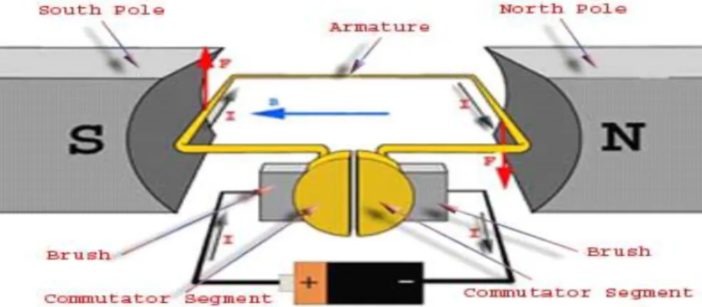
To clearly understand the principle of DC motor, we need to determine the magnitude of the power by considering the diagram below. The Arduino software is published as open source tools, available for extension by experienced programmers. The language can be extended by C++ libraries, and people who want to understand the technical details can make the jump from Arduino to the AVR C programming language on which it is based.
The Arduino software (IDE) uses the concept of a sketchbook, a default place to store our programs (or sketches). The first time we run the Arduino software, it will automatically create a folder for our sketchbook. We can see or change the location of the sketchbook location from with the Options dialog box.
Some preferences can be set in the preferences dialog (found under the Arduino menu on Mac or File on Windows and Linux). The rest can be found in the preferences file, the location of which is shown in the preferences dialog.
WIRES
POWER SUPPLY 12 VOLT
- SPECIFICATIONS
- COST SHEET
Although building on the command line if necessary is possible with some third party tools such as Ino.The. In this chapter we have seen a schematic representation of the project and the various components involved in this project. The resistor is a passive electrical component that creates resistance to the flow of electric current. Electrical networks and electronic circuits can be found in almost all of them. The resistance measured in ohms, an ohm is the resistance that occurs when a current of one ampere passes through it. a resistor with one voltage drop across the terminals. Basically, resistors are used for many purposes such as current, voltage division heat generation, matching and charging circuits.
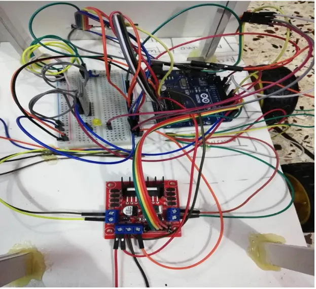
In engineering, switch plays an important role that can break an electrical circuit that supplies one conductor to another conductor. The most identical to manually controlled to electromechanical device either one or more sets of electrical external circuits. Each switch can be in two states, one is open and another is closed. This figure shows the overall project representation of the project and we are able to know in what way each pin of the microcontroller involves this project. The basic function of the application is to control the robot (created with Arduino and Magician Chassis). These Android applications are used to design.
This includes operating machinery, palatalizing, and various metalworking and plastic bulking operations. In the cement industry, machines are controlled by robots. The main purpose of such a robot system is to help people with motor disabilities to fully exercise control. In the future, we will use a secure wireless channel using secret writing and cryptography. Many capabilities will be provided in the future such as AI gestures, speech to text translation and many of extra. It is also within the agricultural sector to be additionally developed under artificial intelligence. In the future, this project will develop a larger bandwidth system.
CONCLUTION
SOFTWARE ANALYSIS………………………….. (34-37)
DESCRIPTION OF OUR SOFTWARE
A schematic, or schematic diagram, is an illustration of the elements of a system using abstract, graphic symbols instead of realistic pictures. In an electronic circuit diagram, the representation of symbols may not resemble the representation in the physical circuit. The arrangement of the interconnections of the components in the diagram does not correspond to their physical location in the finished device.
The design includes all functions of a microprocessor, CPU, ALU, PC, SP and registers. From this chapter we conclude that a schematic diagram is a representation of the elements of a system, using abstract, graphic symbols rather than realistic images. Bluetooth SPP test is an Android application to move the robot. This is also available in the Google Play Store.
It is also an android app to move robo. It is also available on the Google Play Store. The working mechanism of the robot is based on the information transmitted from the android mobile via Bluetooth connection to the robot using a Bluetooth modem and vice versa.
FLOW CHART AND DIAGRAM
CONCLUTION
SCHEMATIC REPRESENTATION……………… (38-43)
SCHEMATIC DIAGRAM
- CRYSTAL OSCILIATOR
- RESISTOR
- SWITCHES
- MOTORS
- LCD
- MICROCONTROLLER
- DRIVER MODULE
- CHARGED BATTARIES
- REGULATION
- CONNECTING WIRES
It is an electronic circuit that uses the mechanical resonance of a moving crystal of piezoelectric material to make an electrical signal with an incredibly precise frequency. Using an amplifier and feedback, this is a particularly accurate form of an electronic oscillator. A current-carrying conductor produces a magnetic field and torque when placed in an external magnetic field.
LCD stands for liquid crystal display is a flat screen made up of colors or pixels in front of a light source. It is common for an LCD to control an attached device. Each pixel consists of a liquid crystal display column between two transparent electrodes. In this chapter we will discuss about the assembly process of voice control robot through android and assembly method. What we have given to the robot via android, whether it is voice command or touch command, the following commands are the same for the movement of the robot.
Nowadays due to higher affordable cost and simplicity through connecting smart phones and tabs respectively. Recently the popularity of home automation has increased greatly in recent years. Surveillance is the monitoring of changing behavior, activities, or other information, usually of people, for the purpose of influencing, managing, directing, or protecting them.
CONCLUTION
RESULTS AND DISCUSSION………………… (44-48)
- ASSEMBLING THE BOARD
- ASSEMBLING THE PROCESS
- COMPLETION OF ASSEMBLING PROCESS…
- ANDROID APPLICATION
- BLUETOOTH SPP TEST
- BLUETOOTH AMR (ANDROID MEETS ROBOT) 47
- TESTING
- CONCLUSION
- APPLICATIONS
- HOME AUTOMATION
- WHEEL CHAIRS
- SURVILLANCE DEVICE
- MILITTARY APPLICATIONS
- DISADVANTAGES
- FUTURE SCOPES
However, within the Android applications, the commands are used to control the robots and in addition, in this chapter we will discuss the robot's operating mechanism. It is a very simple robot platform consisting of four gear motors and wheels and many construction elements such as screws. Assembling the chassis may take some time, but it comes with detailed information so it is not difficult to assemble the parts.
There are numbered screws and the plates have numbered mounting holes for equivalent screws. The final product pictured below is a robot motion frame that can gain momentum when connected to a power source. Mainly to manage our project, the robot is controlled by giving specific commands in amr voice applications.
It can also be used to recognize multiple modes such as clockwise, counterclockwise, forward and backward.