i
SONARGAON UNIVERSITY
“
DESIGN AND IMPLEMENTATION OF IoT BASED SMART ENERGY METER FOR REMOTE MOMITORING AND BILLING SYSTEM”
SUBMITTED BY:
Mohd. Shahnewaz Rubel ID: EEE-1801013174 Shamim Bhuyan ID: EEE-1801013077 Md. Sohel Mia ID: EEE-1801013094 Md. Ajijur Rahman ID: EEE-1703012037 Md. Hashenur Rahman ID: EEE-1801013153
A project submitted in partial fulfillment of the requirements for the degree of Bachelor of Science
In
ELECTRICAL AND ELECTRONIC ENGINEERING (EEE)
Sonargaon University (SU)ii
Declaration
It is declared that project paper or any part of it has not been submitted to anywhere else for the award to any degree.
Signature of Candidates
……….
……….
Mohd. Shahnewaz Rubel
Shamim Bhuyan
……….. ……….
Md. Sohel Mia Md. Ajijur Rahman
………
Md. Hashenur Rahman
iii
Certification
This is to certify that the B.Sc. project entitled “DESIGN AND IMPLEMENTATION OF IoT BASED SMART ENERGY METER FOR REMOTE MOMITORING AND BILLING SYSTEM” submitted by
Mohd. Shahnewaz Rubel ID: EEE-1801013174
Shamim Bhuyan ID: EEE-1801013077
Md. Sohel Mia ID: EEE-1801013094
Md. Azizur Rahman ID: EEE-1703012037 Md. Hashenur Rahman ID: EEE-1801013153
The project represents an independent and original work on the part of the candidates. The research work has not been previously formed the basis for the award of any degree, Diploma, Fellowship or any other discipline.
The whole work of this project has been planned and carried out by this group under the supervision and guidance of faculty member of Sonargaon University, Dhaka, Bangladesh.
Supervisor
………..
TABASSUM ALAM MEEM LECTURER (EEE)
Department of Electrical and Electronic Engineering
iv
Acknowledgement
At First, we think to Almighty Allah for giving patience to complete the project work on ―
DESIGN AND IMPLEMENTATION OF IoT BASED SMART ENERGY METER FOR REMOTE MOMITORING AND BILLING SYSTEM ‘’‖ We would like to convey our heartiest felicitation, best gratitude, humblest thanks to our honorable supervisor Tabassum Alam Meem, Lecturer of Electrical & Electronics Engineering Sonargaon University (SU) for her sincere guidance, kind Co-operation, Supervision, Constant encouragement and valuable suggestion. We would like to express heartiest gratitude to our Head (EEE), Prof. Dr. M.
Bashir Uddin and Coordinator, Ferdous khan for their valuable support and guidance.
Also, thanks to our parents, all friends and lab assistants who helped us and inspired us to do the best
Finally, we wish to acknowledge those who directly or indirectly helped us in connection with the work.
v
Abstract
The Plan improvement of a keen observing and controlling framework for energy meters continuously has been discussed in this paper. The framework can screen the status and send data to web server and additionally a through GSM will sent SMS, cell phone using BLYNK apps and also amount to be paid by customer at the end of month automatically for the next month with current usage statistics SMS. The web page which we will utilize is secret phrase ensure by adding user name and password along with secured keys. The framework offers a total minimal effort, and easy to use method for ongoing observing and remote control of appliances.
vi
Contents
Name of Contents Page No
Certificate ii
Declaration iii
Acknowledgement iv
Abstract v
List of Figures ix
List of Tables x
Chapter 1: Introduction
1.1 Introduction 01
1.2 Objectives of the Project 04
1.3 Project Report Organization 04
Chapter 2: System Design
2.1 Introduction 05
2.2 Block Diagram 05
2.3 Circuit Diagram 06
2.4 Flow Chart 07
Chapter 3: Hardware Implementation
3.1 Introduction 08
3.2 Components 08
3.3 Arduino Uno 09
3.3.1 Introduction to Arduino Uno 10
3.3.2 Pin Description of Arduino Mega 10
3.3.3 Pin Specification 11
3.3.4 Atmega2560 Microcontroller 12
3.3.5 Advanced RISC Architecture 12
3.3.6 High Endurance Non-volatile Memory Segments 13
3.3.7 Peripheral Features 13
3.3.8 Special Microcontroller Features 13
3.3.9 I/O and Packages 14
3.3.10 Operating Voltage 14
3.3.11 Temperature Range 14
3.3.12 Speed Grad 15
3.4 ESP8266 16
3.4.1 Features 16
3.4.2 Pin out 17
3.5 GSM 18
3.6 LCD 16*2 18
3..6.1 Features 19
vii
3.6.2 Pin Symbol I/O Description 19
3.6.3 Logic Status on control lines 20
3.7 Digital Energy Meter 20
3.8 DS3231 22
3.8.1 Benefits and Features 23
3.8.2 Application 23
3.9 SD Card Module 24
3.10 4N35 25
3.10.1 Features 26
3.10.2 Application 26
3.11 Jumper Wire 26
Chapter 4: Experimental Results and Discussion
4.1 Introduction 28
4.2 Project Picture 28
4.3 Advantages 30
4.4 Application 30
4.5 Cost Analysis 31
Chapter 5: Conclusion and Future Scope
5.1 Conclusion 32
5.2 Future Work 32
References 33
Appendix 34
viii
List of Figures
Figure No Title of Figure Page No
Figure 2.1 Block Diagram 05
Figure 2.2 Circuit Diagram 06
Figure 2.3 Flow Chart 07
Figure 3.1 Arduino Mega 09
Figure 3.2 Pin Description of Arduino Mega 10
Figure 3.3 Atmega2560 Microcontroller Features 12
Figure 3.4 Esp8266 15
Figure 3.5 GSM 17
Figure 3.6 LCD 16*2 18
Figure 3.7 Digital Energy Meter 21
Figure 3.8 DS3231 22
Figure 3.9 SD Card Module 24
Figure 3.10 4N35 25
Figure 3.11 Jumper Wire 26
Figure 4.1 Picture of Project 28
ix
List of Tables
Table No. Title of Table Page No
Table 3.1 LCD pin symbol I/O description 16
Table 4.1 Cost Analysis 24
1
Chapter 1: Introduction
1.1 Introduction
In the present billing system, the distribution companies are unable to keep track of the changing maximum demand of consumers. The consumer is facing problems like receiving due bills for bills that have already been paid as well as poor reliability of electricity supply and quality even if bills are paid regularly. The remedy for all these problems is to keep track of the consumers load on timely basis, which will held to assure accurate billing, track maximum demand and to detect threshold value. These are all the features to be taken into account for designing an efficient energy billing system.
2
The present project “DESIGN AND IMPLEMENTATION OF IoT BASED SMART ENERGY METER FOR REMOTE MOMITORING AND BILLING SYSTEM” addresses the problems faced by both the consumers and the distribution companies.
The paper mainly deals with smart energy meter, which utilizes the features of embedded systems i.e. combination of hardware and software in order to implement desired functionality.
The paper discusses comparison of Microcontroller, and the application of Data logger and Wi- Fi modems to introduce ‘Smart’ concept. With the use of IoT modem the consumer as well as service provider will get the used energy reading with the respective amount, Consumers will even get notification in the form text through IoT when they are about to reach their threshold value, that they have set. Also, with the help of Wi-Fi modem the consumer can monitor his consumed reading and can set the threshold value through webpage.
3
This system enables the electricity department to read the meter readings monthly without a person visiting each house. This can be achieved by the use of microcontroller unit that continuously monitor and records the energy meter reading in its permanent (non-volatile) memory location. This system continuously records the reading and the live meter reading can be displayed on webpage to the consumer on request.
This system also can be used to disconnect the power supply of the house when needed.
4
1.2 Objectives of the Project
The general objectives of this system are summarized below:
➢ To develop an IoT based online energy meter.
➢ To monitor the energy of consumer from anywhere.
➢ To Save the Data
➢ To Send SMS Authorized Person.
1.3Project Report Organization
In chapter one, we describe the Overview, Literature review and project objectives of IoT based Smart Energy Meter with data logger.
In chapter second, we briefly describe the project Block Diagram, Circuit Diagram and Flow chart.
In chapter third, we implement those components which we used in the Arduino mega, GSM, LCD 16*2, ESP8266 and its Hardware Analysis.
In chapter fourth, we describe the Experimental Results and Discussion.
Finally, in chapter fifth, we discuss about project’s Conclusion and Future work of IoT based Smart Energy Meter with data logger.
5
Chapter 2: System Design
2.1 Introduction
In this chapter we will discuss about block diagram, circuit diagram, working process and flow chart.
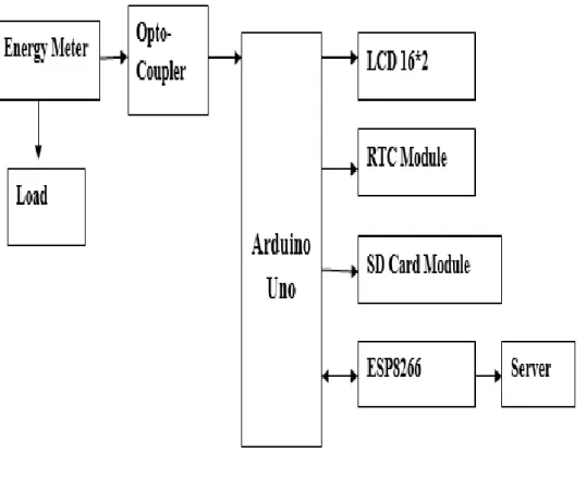
2.2 Block Diagram
Figure 2.1 Block Diagram
6
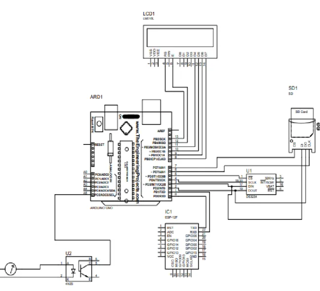
2.3 Circuit Diagram
Figure 2.2Circuit Diagram
7
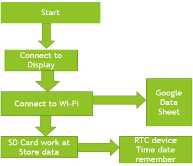
2.4 Flow Chart
Figure 2.3 Flow Chart
8
Chapter 3: Hardware Implementation
3.1 Introduction
In this chapter we have followed-up the theory of Energy Meter, Arduino Mega, ESP8266, RTC module, SD Card Module, GSM Module, Jumper Wire, Power Supply and others components. Here we can know that the total system overview of the projects. And we will also know that how the equipment is working with each other.
3.2 Components
➢ Energy Meter
➢ Arduino Uno
➢ ESP8266
➢ RTC Module
➢ SD Card Module
➢ LCD 16*2
➢ LED
➢ Jumper Wire
➢ Power Supply
9
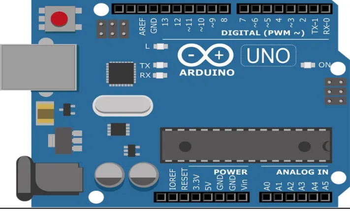
3.3 Arduino Uno
Figure 3.1 Arduino Uno
Arduino is an open-source physical computing platform based on simple input/output board and a development environment that implements the Processing language.
10 3.3.1 Introduction to Arduino Boards
Arduino is an architecture that combines Atmel microcontroller family with standard hardware into a board with inbuilt boot loader for plug and play embedded programming. Arduino Software comes with an IDE that helps writing, debugging and burning program into Arduino.
The IDE also comes with a Serial Communication window through which can easily get the serial data from the board.
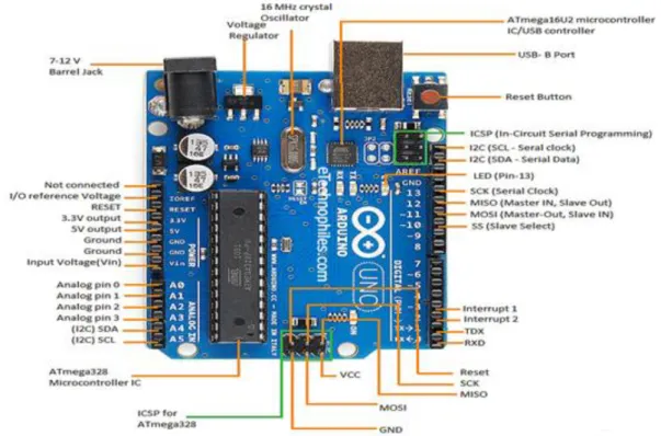
3.3.2 Pin Description of Arduino Uno
Figure 3.2 Pin Description of Arduino Uno
The Arduino Uno is a microcontroller board based on the ATmega2560. It has 54 digital input/output pins (of which 14 can be used as PWM outputs), 16 analog inputs, a 16 MHz
11
quartz crystal, a USB connection, a power jack, an ICSP header and a reset button. Each of the 14 digital pins can be used as an input or output, using pin Mode (), digital Write (), and digital Read () functions. They operate at 5 volts. Each pin can provide or receive 20 mA as recommended operating condition and has an internal pull-up resistor (disconnected by default) of 20-50k ohm. A maximum of 40mA is the value that must not be exceeded on any I/O pin to avoid permanent damage to the microcontroller.
3.3.3 Pin Specification
Serial: 0(RX) and 1(TX). Used to receive (RX) and Transmit (TX) TTL serial data.
External Interrupts: 2 and 3. These pins can be configured to trigger an interrupt on a low value, a rising or falling edge, or a change in value.
PWM: 3, 5, 6, 9, 10, and 11. Provide 8-bit PWM output with the analog Write () function.
SPI: 10(SS), 11(MOSI), 12(MISO), 13(SCK). These pins support SPI communication using the SPI library.
LED: 13. There is a built-in LED driven by digital pin13.
TWI: A4 or SDA pin and A5 or SCL pin. Support TWI communication using the wire library.
The Uno has 6 analog inputs, labeled A0 through A5, each of which provide 10 bits of resolution. By default, they measure from ground to 5 volts, through is it possible to change the upper end of their range using the AREF pin and the analog Reference () function. There are a couple of other pins on the board. AREF Reference voltage for the analog inputs. Used with analog Reference.
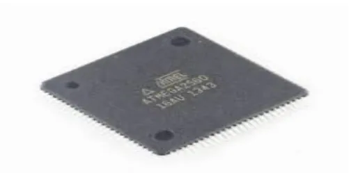
12 3.3.4Atmega328 Microcontroller
The high-performance Microchip 8-bit AVR RISC-based microcontroller combines 250 KB ISP flash memory with read-while-write capabilities, 1KB EEPROM, 2KB SRAM, 23 general purpose I/O lines, 86 general purpose working registers, three flexible timers/counters with compare modes, internal and external interrupts, serial programmable USART, a byte-oriented 2-wire serial interface, SPI serial port, 6-channel 10-bit A/D
Converter (8-channels in TQFP and QFN/MLF packages), programmable watchdog timer with internal oscillator, and five software selectable power saving modes. The device operates between 1.8-5.5 volts. By executing powerful instructions in a single clock cycle, the device achieves throughputs approaching 1 MIPS per MHz, balancing power consumption and processing speed.
Figure 3.3 Atmega328 Microcontroller Features
High Performance, Low Power Atmel AVR 8-Bit Microcontroller Family 3.3.5 Advanced RISC Architecture
➢ 131 Powerful Instructions – Most Single Clock Cycle Execution
➢ 32 x 8 General Purpose Working Registers
➢ Fully Static Operation
➢ Up to 20 MIPS Throughput at 20MHz
➢ On-chip 2-cycle Multiplier
13
3.3.6 High Endurance Non-volatile Memory Segments
➢ 4/8/16/32KBytes of In-System Self-Programmable Flash program memory
➢ 256/512/512/1KBytes EEPROM
➢ 512/1K/1K/2KBytes Internal SRAM
➢ Write/Erase Cycles: 10,000 Flash/100,000 EEPROM
➢ Data retention: 20 years at 85ºC/100 years at 25ºC
➢ Optional Boot Code Section with Independent Lock Bits
➢ In-System Programming by on-chip Boot Program
➢ True Read-While-Write Operation
➢ Programming Lock for Software Security
3.3.7 Peripheral Features
➢ Two 8-bit Timer/Counters with Separate Pre scaler and Compare Mode
➢ One 16-bit Timer/Counter with Separate Pre scaler, Compare Mode, and Capture Mode
➢ Real Time Counter with Separate Oscillator
➢ Six PWM Channels
➢ 8-channel 10-bit ADC in TQFP and QFN/MLF package
➢ Temperature Measurement
➢ 6-channel 10-bit ADC in PDIP Package 3.3.8 Special Microcontroller Features
➢ Power-on Reset and Programmable Brown-out Detection
➢ Internal Calibrated Oscillator
➢ External and Internal Interrupt Sources
➢ Six Sleep Modes: Idle, ADC Noise Reduction, Power-save, Power-down, Standby, and Extended Standby
3.3.9 I/O and Packages
➢ 23 Programmable I/O Lines
➢ 28-pin PDIP, 32-lead TQFP, 28-pad QFN/MLF and 32-pad QFN/MLF
14 3.3.10 Operating Voltage
➢ 1.8V to 5.5V
3.3.11 Temperature Range
➢ 40°C to 85°C 3.3.12 Speed Grade
➢ 0 - [email protected] - 5.5V, 0 - [email protected] - 5.5.V, 0 - 20MHz @ 4.5 - 5.5V
➢ Power Consumption at 1MHz, 1.8V, 25°C
➢ Active Mode: 0.2mA
➢ Power-down Mode: 0.1µA
15
3.4 ESP8266
Figure 3.4 Esp8266 [2]
The ESP8266 is a low-cost Wi-Fi microchip, with a full and microcontroller capability, produced by Expressive in Shanghai, China.
The chip first came to the attention of Western makers in August 2014 with the ESP- 01 module, made by a third-party manufacturer Ai-Thinker. This small module allows microcontrollers to connect to a Wi-Fi network and make simple TCP/IP connections using Hayes-style commands. However, at first there was almost no English-language documentation on the chip and the commands it accepted. The very low price and the fact that there were very few external components on the module, which suggested that it could eventually be very inexpensive in volume, attracted many hackers to explore the module, the chip, and the software on it, as well as to translate the Chinese documentation. The ESP8285 is
16
an ESP8266 with 1 MiB of built-in flash, allowing the building of single-chip devices capable of connecting to Wi-Fi.
3.4.1 Features
➢ Processor: L106 32-bit RISC microprocessor core based on the Ten silica Extensa Diamond Standard 106Micro running at 80 MHz
➢ Memory:
➢ 32 KiB instruction RAM
➢ 32 KiB instruction cache RAM
➢ 80 KiB user-data RAM
➢ 16 KiB ETS system-data RAM
➢ External QSPI flash: up to 16 MiB is supported (512 KiB to 4 MiB typically included)
➢ IEEE 802.11 b/g/n Wi-Fi
➢ Integrated TR switch, balun, LNA, power amplifier and matching network
➢ WEP or WPA/WPA2 authentication, or open networks
➢ 16 GPIO pins
➢ SPI
➢ I²C (software implementation)
➢ I²S interfaces with DMA (sharing pins with GPIO)
➢ UART on dedicated pins, plus a transmit-only UART can be enabled on GPIO2
➢ 10-bit ADC (successive approximation ADC) 3.4.2 Pinout
The pin out is as follows for the common ESP-01 module:
➢ GND, Ground (0 V)
➢ GPIO 2, General-purpose input/output No. 2
➢ GPIO 0, General-purpose input/output No. 0
➢ RX, Receive data bit X, also GPIO3
➢ VCC, Voltage (+3.3 V; can handle up to 3.6 V)
➢ RST, Reset
➢ CH_PD, Chip power-down
➢ TX, Transmit data bit X, also GPIO1
17
3.5 GSM
Figure 3.5 GSM
The GSMA6 is a cheap and portable GSM breakout board with all the capabilities of the larger SIM900 shields. In this Arduino SIM800L tutorial, I will help you get started with this nifty device. Sending and receiving texts with your Arduino have never been easier. Smallest SIM800L GPRS GSM Module Micro SIM Card Core Board Quad-band TTL Serial Port.
Specifications:
➢ Chip: SIM800L
➢ Voltage:3.7-4.2V
➢ Support networks: China Mobile, China Unicom and global quad-band network
➢ Module size:2.5cmx2.3cm
➢ TTL serial port for serial port, you can link directly to the microcontroller.
➢ Power module automatically boot, homing network.
➢ Onboard signal lights all the way. It flashes slowly when there isa signal, it flashes quickly when there is no signal.
This GSMA6 breakout board is ideal for projects that needs to save space. In fact, this is the one I used when I created my own cell phone. This board draws a maximum of 2 A with an input voltage of 3.7 V to 4.2 V. This means you must not connect its pins directly to a 5 V Arduino! It doesn't even run on 3.3 V.
The SIM card mounted GSM modem upon receiving digit command by SMS from any cell phone sends that data to the MC through serial communication. While the program is
executed, the GSM modem receives the command 'STOP' to develop an output at the MC, the contact point of which are used to disable the ignition switch.
18
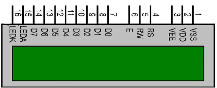
3.6 LCD 16*2
Some of the most common LCDs connected to the Arduino Uno are 16*2. This means 16 characters per line by 2 lines and in recent years the LCD is finding widespread use replacing LED’s.
Figure 3.6 LCD 16*2
Fortunately, a very popular standard exists which allows us to communicate with the vast majority of LCDs regardless of their manufacturer. The standard is referred to as HD44780U, which refers to the controller chip which receives data from an external source and communicates directly with the LCD. The 44780 standard requires 3 control lines as well as either 4 or 8 I/O lines for the data bus. The user may select whether the LCD is to operate with a 4-bit data bus or an 8-bit data bus. If a 4-bit data bus is used the LCD will require a total of 7 data lines (3 control lines plus the 4 lines for the data bus). If an 8-bit data bus is used the LCD will require a total of 11 data lines (3 control lines plus the 8 lines for the data bus).
3.6.1 Features
➢ Display data RAM
➢ Character generator ROM
➢ 160 different 57 dot matrix character patterns.
➢ Display data RAM and Character generator RAM may be accessed by the microprocessor.
➢ Numerous instruction
19
➢ Clear Display, Cursor Home, Display ON/OFF, Cursor ON/OFF, Blink Character, Cursor Shift.
➢ Built in reset circuit is triggered at power ON.
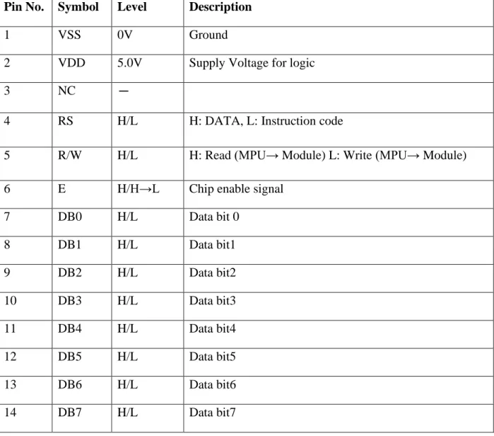
3.6.2 Pin Symbol I/O Description
Pin No. Symbol Level Description
1 VSS 0V Ground
2 VDD 5.0V Supply Voltage for logic
3 NC -
4 RS H/L H: DATA, L: Instruction code
5 R/W H/L H: Read (MPU→ Module) L: Write (MPU→ Module)
6 E H/H→L Chip enable signal
7 DB0 H/L Data bit 0
8 DB1 H/L Data bit1
9 DB2 H/L Data bit2
10 DB3 H/L Data bit3
11 DB4 H/L Data bit4
12 DB5 H/L Data bit5
13 DB6 H/L Data bit6
14 DB7 H/L Data bit7
Table 3.2 LCD pin symbol I/O description
3.6.3 Logic Status on control lines
➢ E- 0 Access to LCD Disabled
➢ -1 Access to LCD enabled
➢ R/W – 0 Writing data to LCD
➢ 1 Reading data from LCD
➢ RS – 0 Instructions
20
➢ Writing data to the LCD
➢ Set R/W bit to low
➢ Set RS bit to logic 0 or 1
➢ Set data to data lines
➢ Set E line to high
➢ Set E line to low
➢ Read data from data lines
➢ Set R/W bit to high
➢ Set RS bit to logic 0 or 1
➢ Set data to data lines
➢ Set E line to high
➢ Set E line to low
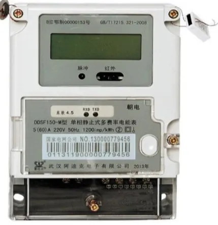
3.7 Digital Energy Meter
An electric meter or energy meter is an essential device that goes with consumption of commercially distributed energy.
An electric meter or energy meter is an essential device that goes with consumption of commercially distributed energy. It enables systematic pricing of energy consumed by individual consumer as it measures the amount of electrical energy consumed by a residence, business, or an electrically powered device. They are typically calibrated in billing units, the most common one being the Kilowatts hour, which is equal to the amount of energy used by a load of one kilowatt over a period of one hour, or 3,600,000 joules.
21
Figure 3.7 Digital Energy Meter
Some meters measured only the length of time for which charge flowed, with no measurement of the magnitude of voltage or current. These were only suited for constant-load applications.
Neither type is likely to be used today. In addition to metering based on the amount of energy used, other types of metering are available. Meters which measured the amount of charge (coulombs) used, known as ampere-hour meters, were used in the early days of electrification.
These were dependent upon the supply voltage remaining constant for accurate measurement of energy usage, which was not a likely circumstance with most supplies.
Generally, electricity meters operate by continuously measuring the instantaneous voltage (volts) and current (amperes) and finding the product of these to give instantaneous electrical power (watts) which is then integrated against time to give energy used (Joules, Kilowatt-hours etc.). Meters for smaller services (such as small residential customers) can be connected directly in-line between source and customer. For larger loads, more than about 200 amps of load, current transformers are used, so that the meter can be located other than in line with the service conductors. The meters fall into two basic categories, electromechanical and electronic.
This paper dwells on the electronic meter.
22
3.8 DS3231
The DS3231 is a low-cost, extremely accurate I2C real-time clock (RTC) with an integrated temperature compensated crystal oscillator (TCXO) and crystal. The device incorporates a battery input, and maintains accurate timekeeping when main power to the device is interrupted. The integration of the crystal resonator enhances the long-term accuracy of the device as well as reduces the piece-part count in a manufacturing line. The DS3231 is available in commercial and industrial temperature ranges, and is offered in a 16-pin, 300-mil SO package.
Figure 3.8 DS3231
The RTC maintains seconds, minutes, hours, day, date, month, and year information. The date at the end of the month is automatically adjusted for months with fewer than 31 days, including corrections for leap year. The clock operates in either the 24-hour or 12-hour format with an AM/PM indicator. Two programmable time-of-day alarms and a programmable square-wave output are provided. Address and data are transferred serially through an I2C bidirectional bus.
A precision temperature-compensated voltage reference and comparator circuit monitors the status of VCC to detect power failures, to provide a reset output, and to automatically switch
23
to the backup supply when necessary. Additionally, the RST pin is monitored as a pushbutton input for generating a μP reset.
3.8.1 Benefits and Features
Highly Accurate RTC Completely Manages All Timekeeping Functions
➢ Real-Time Clock Counts Seconds, Minutes, Hours, Date of the Month, Month, Day of the Week, and Year, with Leap-Year Compensation Valid Up to 2100
➢ Accuracy ±2ppm from 0°C to +40°C
➢ Accuracy ±3.5ppm from -40°C to +85°C
➢ Digital Temp Sensor Output: ±3°C Accuracy
➢ Register for Aging Trim
➢ RST Output/Pushbutton Reset Debounce Input
➢ Two Time-of-Day Alarms
➢ Programmable Square-Wave Output Signal
➢ Simple Serial Interface Connects to Most Microcontrollers
➢ Fast (400kHz) I2C Interface
➢ Battery-Backup Input for Continuous Timekeeping
➢ Low Power Operation Extends Battery-Backup Run Time
➢ 3.3V Operation
➢ Operating Temperature Ranges: Commercial (0°C to +70°C) and Industrial (-40°C to +85°C
3.8.2 Applications
➢ Servers
➢ Telematics
➢ Utility Power Meters
➢ GPS
3.9 SD Card Module
24
Figure 3.9 SD Card Module
The SD Card Module is a simple solution for transferring data to and from a standard SD card.
The pinout is directly compatible with Arduino, but can also be used with other microcontrollers. This module has SPI interface which is compatible with any SD card and it use 5V or 3.3V power supply.SD module has various applications such as data logger, audio, video, graphics.
3.10 4N35
25 Figure 3.10 4N35
Up to coupler does is to break the connection between signal source and signal receiver, so as to stop electrical interference. In other words, it is used to prevent interference from external electrical signals. 4N35 can be used in AV conversion audio circuits.
26
3.10.1 FEATURES
• Isolation test voltage 5000 VRMS • Interfaces with common logic families • Input-output coupling capacitance < 0.5 pF • Industry standard dual-in-line 6 pin package.
3.10.2 APPLICATIONS
• AC mains detection
• Reed relay driving
• Switch mode power supply feedback • Telephone ring detection
• Logic ground isolation
• Logic coupling with high frequency noise rejection
3.11 Jumper Wire
Figure 3.11 Jumper Wire
A jump wire (also known as jumper wire, or jumper) is an electrical wire, or group of them in a cable, with a connector or pin at each end (or sometimes without them – simply "tinned"),
27
which is normally used to interconnect the components of a breadboard or other prototype or test circuit, internally or with other equipment or components, without soldering. Individual jump wires are fitted by inserting their "end connectors" into the slots provided in a breadboard, the header connector of a circuit board, or a piece of test equipment.
Chapter 4: Experimental Results and
Discussion
28
4.1 Introduction
In this chapter we will discuss about experimental results, Advantages, application, cost analysis of the project.
Implementation A prototype low-cost data logger and monitoring energy consumption in this project, the energy meter shows the power consumption when the different loads of the house are running. We have used data logger with it to make that energy meter smart energy meter, here the reading of energy meter through microcontroller is saved in data logger with the help of IoT and RTC. And this data is time, date, unit and amount of cost. Shows in Google Excel.
We see that the LED of the meter glows incessantly which counts for the meter reading. The units are calculated based on the flashing. Typically, this meter blinks twice a minute. The price of one unit has been fixed at 5 BDT.
4.2 Project Picture
With Load
29
With Out Load
Figure 4.1 Picture of Project
30
4.3 Advantages
➢ The System provides more accurate identification.
➢ Quick and Rapid: Identifies candidates in seconds.
➢ The System is less tedious, cost-efficient, easy to use, hard to adulterate and modest.
➢ Highly accurate
➢ Real time operation
➢ Fully automated
➢ Live billing display facility
➢ Previous Units display Facility
4.4 Application
➢ It is only use for electricity measurement
4.5 FUTURE IMPLEMENTATION
• We can use this method not-only for Electricity measurement, but also for Gas &
Water measurement
31
4.5 Cost Analysis
Table 4.1 Cost Analysis
Chapter 5: Conclusion and Future Scope
32
5.1 Conclusion
This System helps in controlling energy consumption and avoiding energy wastage is very important. This system is based on a microcontroller and implementation of energy meter using IoT concept and Data logger concept.
In the proposed system, IoT and data logger based energy meter reading system. It plays a vital role to continuously monitor the meter reading and transfer the reading to a central server. This data can be accessed from anywhere on the globe at any time.
5.2 Future Work
➢ It’s a no only use for electricity measurement but it also measures: Gas & Water.
➢ We will do add new feature to implement in digital measurement to provide wireless communication to protect against theft
References
33 [1] https://www.arduino.cc
[2] https://www.esp8266.com
[3] https://components101.com/displays/16x2-lcd-pinout-datasheet
[4] https://www.globalspec.com/learnmore/electrical_electronic_components/power_supplies _conditioners/ac_dc_converters
[5] https://uk.rs-online.com/web/p/breadboard-jumper-wire-kits/7916463 [6] https://nettigo.eu/products/sim800l-gsm-grps-module
[7] https://www.vishay.com/docs/81181/4n35.pdf
[8] https://create.arduino.cc/projecthub/electropeak/sd-card-module-with-arduino-how-to- read-write-data-37f390
[9] https://lastminuteengineers.com/ds3231-rtc-arduino-tutorial/
[10] https://www.directindustry.com/prod/ningbo-sanxing-electric-co-ltd/product-162297- 2342230.html
34
Appendix
Programming Codes for Proposed Project
#include <LiquidCrystal.h>
int currentPin = 1; //Assign CT input to pin 1 double kilos = 0;
int peakPower = 0;
LiquidCrystal lcd(8, 9, 4, 5, 6, 7); //Assign LCD screen pins, as per LCD shield requirements
void setup() {
lcd.begin(16,2); // columns, rows. use 16,2 for a 16x2 LCD, etc.
lcd.clear();
lcd.setCursor(0,0); // set cursor to column 0, row 0 (the first row) lcd.print("Running");
}
void loop() {
int current = 0;
int maxCurrent = 0;
int minCurrent = 1000;
35
for (int i=0 ; i<=200 ; i++) //Monitors and logs the current input for 200 cycles to determine max and min current
{
current = analogRead(currentPin); //Reads current input and records maximum and minimum current
if(current >= maxCurrent) maxCurrent = current;
else if(current <= minCurrent) minCurrent = current;
}
if (maxCurrent <= 517) {
maxCurrent = 516;
}
double RMSCurrent = ((maxCurrent - 516)*0.707)/11.8337; //Calculates RMS current based on maximum value
int RMSPower = 220*RMSCurrent; //Calculates RMS Power Assuming Voltage 220VAC, change to 110VAC accordingly
if (RMSPower > peakPower) {
peakPower = RMSPower;
}
kilos = kilos + (RMSPower * (2.05/60/60/1000)); //Calculate kilowatt hours used delay (2000);
lcd.clear();
lcd.setCursor(0,0); // Displays all current data
lcd.print(RMSCurrent);
36 lcd.print("A");
lcd.setCursor(10,0);
lcd.print(RMSPower);
lcd.print("W");
lcd.setCursor(0,1);
lcd.print(kilos);
lcd.print("kWh");
lcd.setCursor(10,1);
lcd.print(peakPower);
lcd.print("W");
}
![Figure 3.4 Esp8266 [2]](https://thumb-ap.123doks.com/thumbv2/filepdfnet/10657956.0/24.892.130.853.234.665/figure-3-4-esp8266-2.webp)