This is to certify that this project titled “DUAL AXIS SOLAR TRACKING SYSTEM” is being done by the following students under my direct supervision. This project work was carried out by them in the laboratories of the Department of Mechanical Engineering under the Faculty of Engineering, Sonargaon University (SU) in partial fulfillment of the requirements for the degree of Bachelor of Science in Mechanical Engineering. The report titled as on “DUAL AXIS SOLAR TRACKING SYSTEM” was prepared to meet the requirement of our practicum program.
During the making and preparation of our practical report, we would like to thank several people for their enormous help and extensive cooperation. In the first place, we would like to express our gratitude to the university authority for allowing us to do our practicum. Particularly, we would like to thank our dear teacher Nuruzzaman Rakib Lecturer, Department of Mechanical Engineering, Sonargaon University (SU), Dhaka for his valuable and patient advice, sympathetic help, cooperation, contribution of new idea.
Deep theoretical and hardware knowledge and keen interest of our supervisor in this field influenced us to carry out this project. Finally, we would like to thank again the respected Vice-Chancellor of Sonargaon University (SU), Professor Dr. Abul Bashar also thanks to Head of Department of Mechanical Engineering, Sonargaon University (SU), Md.
When the light is absorbed by the material, the conductivity of the material is reduced.
Introduction
- Historical Background
- Earlier Research
- Resent research
- State of art technology
- Future Scope of this study
- Future scope
- Recommendation
- Limitations of this study
- Advantage over traditional methods
- Objective of this work
- Primary objectives
- Secondary objectives
- Introduction to the Project
1839 - The Photovoltaic Effect: Edmond Becquerel discovered in 1839 that when two electrodes were placed in an electrolyte (electricity-conducting solution), a voltage developed when light fell on the electrolyte. 1883 - The first working solar cell: American inventor Charles Fritts developed the first solar cell, applying selenium to a thin layer of gold. Although controversial at the time, it was gradually accepted by the scientific community and led to him winning the Nobel Prize in 1921.
Early charge controllers could only reduce the amount of voltage from the PV panels if it was too high for the batteries. At any temperature lower than the maximum, the excess voltage from the PV panels will have to be discarded by the charge controllers. Because PV panels are the most expensive component of the system, the need for extra (or larger) PV panels has negatively affected the cost-effectiveness of such PV power systems.
The US Department of Energy's Solar Research Center in Colorado, along with Florida State University's Solar Research Center at Cape Canaveral, were also involved in early trials of the product. Their goal is to use all the power from the PV panel(s) regardless of the voltage and current at any amount of sun or at any temperature. More specifically, the charge controllers are slow to adapt to changing conditions for the PV panels during a given day, including low light conditions in the morning, evening and under cloud cover and also temperature changes, sometimes associated with the changes in insolation.
Because they do not adapt quickly to changing conditions, charge controllers have limited efficiency, which results in the need for additional (or larger) PV panels to be used for a given power output and high costs . Using the MPPT algorithm, it increases the efficiency of the PV panel and ensures the maximum use of sunlight power. In an extensive new assessment of the status and prospects of solar photovoltaic technology, MIT researchers say it is “one of the few renewable, low-carbon sources with the scalability and technological maturity to meet ever-increasing global demand for electricity. ” The use of solar photovoltaics has grown at a phenomenal rate: Worldwide installed capacity has grown steadily by an average of 43 percent per year since 2000.
Finally, a future work could also improve the developed software to efficiently use the microcontroller's capabilities. A final prototype can then be designed and implemented in order to have a final portable prototype for the solar charger. The whole system in a single integrated. This P&O algorithm increases power transfer efficiency compared to non-MPPT (direct-coupled) systems, reducing PV panel size and cost.
Literature Review
- Block Diagram of This Proposed Project
- The Model of the Project
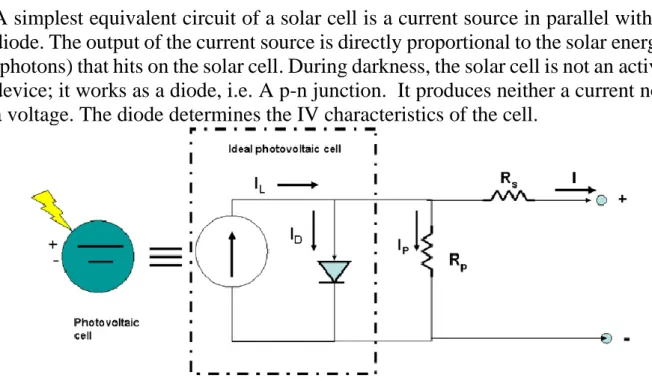
- Photovoltaic cell model
- Maximum Power Point Tracking (MPPT)
- Types of Solar Trackers & System
- Dual axis solar tracker
- Advantages & Disadvantages of solar energy
- Advantages
- Disadvantages
A solar panel is primarily designed as a panel that absorbs sunlight and converts the light into electricity. Most of the time the most powerful light source available is the Sun, called Sol by astronomers. The output of the current source is directly proportional to the solar energy (photons) hitting the solar cell.
Maximum Power Point Tracking (MPPT) is an electronic system that operates the photovoltaic (PV) modules that allows the modules to produce all the power they are capable of. Solar trackers are almost universally used in the case of Solar Thermal Technology because they generate large amounts of energy from sunlight. The use of tracker on solar panel makes this system smart and the tracker tracks the sun rays and it is rotated the panel according to rays.
There are two types of tracker systems and they are single-axis solar tracker and dual-axis solar tracker. Dual axis tracking system uses the solar panel to track the sun from east to west and north to south. The dual-axis solar tracker has two axes of freedom that act as axes of rotation.
Dual axis solar tracker will be reliable and accurate and it maximizes the output to static and single axis tracking system. The controller detects the signal from the LDRs and commands the motor to rotate the panel in the respective direction. There are several advantages that solar energy has that make it favorable for many uses.
On the other hand, the various machines used for pumping oil or generating power are noisy. Solar energy can be used in very remote areas where extending the electricity grid is costly. Solar power stations do not match the power output of similarly sized conventional power plants.

Components, Design & Implementation
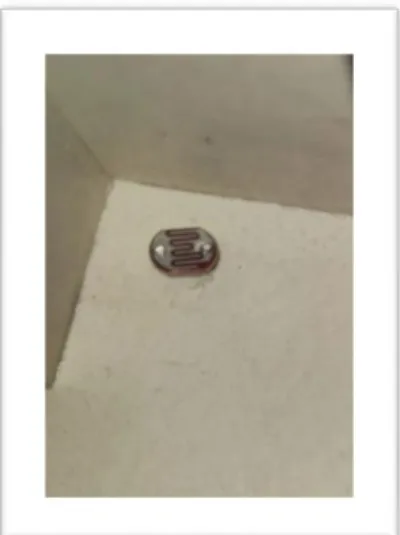
LDR (Light Dependent Resistor)
- Working Principle of LDR
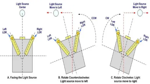
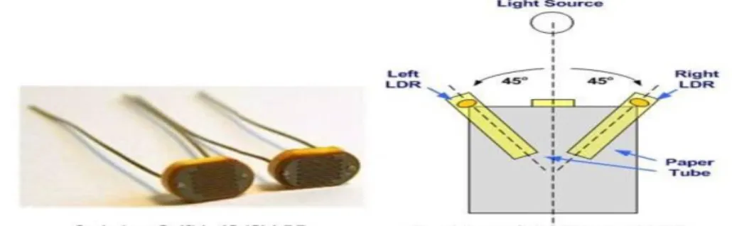
- The Design and implementation of using Four LDRs
This causes the free electrons or holes to conduct electricity and thus lower the resistance (< 1 Kilo ohm). There are several methods that have been proposed and used to track the position of sunlight. A light-dependent resistor separated by a small plate to act as a shield against sunlight, as shown in the following figures.
Both LDRs are connected to a bridge and the output of the bridge is connected to a comparator (microcontroller analog comparator is used). When LDR1 has a higher light intensity than LDR2, the resistance of LDR1 is less than the resistance of LDR2, then the voltage across AIN0 is higher than across AIN1 and the output of the comparator is high. When LDR2 has a higher light intensity than LDR1, the resistance of LDR1 is greater than the resistance of LDR2, then the voltage across AIN0 is less than across AIN1 and the output of the comparator is low.
Then the output of the comparator is used in the UC program to control the stepper motor RV1 variable resistor to balance the bridge when the two LDRs have the same light intensity (due to the mismatch between the two LDRs).
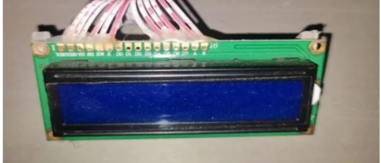
LCD (2 Line 16 Carriers)
- Pin Features
- Pin Description
3 contrast adjustment; though a variable resistor VEE 4 selects command register when low; And Data Resister when.
Servo Motor
SERVO MOTOR SG-90
- Advantages & Disadvantages of using Servo motor
- Microcontroller
- Pin and their functions
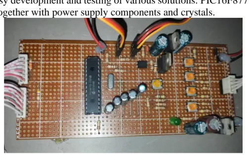
- PIC16F877 Development Board
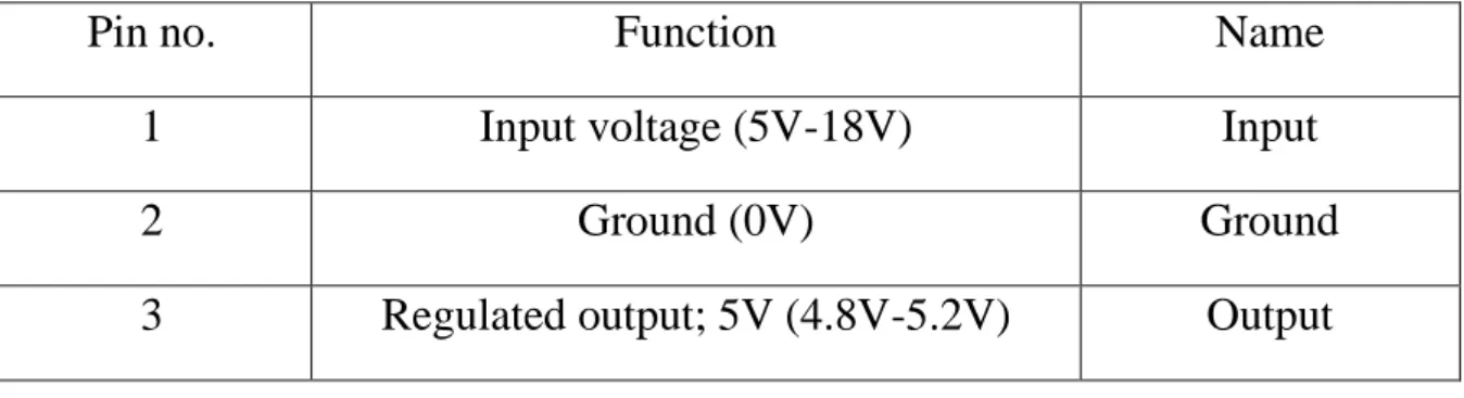
- Voltage regulator
- Pin Description
- Capacitor
- The Designing Tools
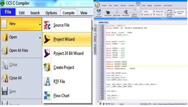
- CCS C Compiler
- Proteus Design Suite
- Crystal
The motor is controlled with an electrical signal that determines the amount of shaft movement. Basically, microcontrollers are used in automatically controlled products and devices, such as automotive engine control systems, implantable medical devices, remote controls, office machines, appliances, power tools, toys, and other embedded systems. A microcontroller is available in different word lengths like microprocessors (4bit, 8bit, 16bit, 32bit, 64bit and 128-bit microcontrollers are available today).
A voltage regulator generates a fixed output voltage from changes to its input voltage or load conditions. IC 7805 is a 5V voltage regulator that limits the voltage output to 5V and draws 5V regulated power supply. The voltage source in a circuit may have fluctuations and will not give the fixed voltage output.
Using capacitor in a microcontroller makes the microcontroller a digital device with fast switching edges that uses a large amount of current for a very short period of time at each transition. The capacitors provide the large amount of current needed so that the power supply does not sag and cause noise during that time. It is always best to use a variety of capacitors on the power supply pins of the microcontroller to provide a low-impedance broadband supply.
Capacitors are used for various purposes such as timing, smooth power supply, coupling, filtering, tuning for radio system, energy storage, etc. We use CCS C as microcontroller programming compiler and Proteus Design Suite as a powerful electronic design application. I think CCS C is the best high level language compiler for PIC microcontroller as it is almost hardware independent.
Optimum capacitor values depend on whether a quartz crystal or ceramic resonator is used. Crystal oscillators are not built into ICs because they cannot be easily fabricated with IC processes and the size is physically larger than IC circuits. The reason crystal oscillators are used is because the quality factor is of the order of 100000 while that of RC oscillators is of the order of 100.
Discussions and Conclusions
Discussion
Suggestion for Future work
- Development of microcontroller
- Development of MPPT system & PV panels
Conclusion