First of all, we thank Almighty Allah from the bottom of our hearts. We would like to express our sincere gratitude to our honorable supervisor MdSojibKaisar, lecturer, Department of Mechanical Engineering, SU, who inspired us at every turn. He has always been extremely generous with his time, knowledge and ideas and has given us great freedom in this research. We would also like to convey our gratitude to Dean Prof. Mohammed A Mabud, Department of Mechanical Engineering, for his help, support and continuous encouragement. We express our humility I would like to thank all the teachers of the Department of Mechanical Engineering for their support in countless ways during this project work.
Finally, we would like to thank our parents who have given us enormous inspiration and support. Today, solar panels have been used more and more in recent years to convert solar energy into electrical energy. The solar panel can be used either as an independent system or as a large system that is connected to the power grid.
To maximize the conversion from solar energy to electricity, the solar panel must be positioned perpendicular to the sun, so tracking the location of the sun and positioning the solar panel are important. The goal of this project is to design and automatic tracking system, which can locate the position of the sun. The tracking system will move the solar panel so that it is positioned perpendicular to the sun for maximum energy conversion at all times.
Introduction
OBJECTIVE
Solar Tracker
Solar power in Bangladesh
Type of Solar Tracker
- Single axis solar tracker
- Dual axis solar tracker
The axis that is fixed relative to the ground can be considered the primary axis. They are classified based on the orientation of their primary axes relative to the ground. Two common implementations are tip-tilt dual-axis trackers (TTDAT) and azimuth-altitude dual-axis trackers (AADAT).
The orientation of the module relative to the tracker axis is important when modeling performance. Dual axis trackers ensure optimal solar energy levels thanks to their ability to track the sun vertically and horizontally. Wherever the sun is in the sky, dual-axis trackers can angle themselves so that they are in direct contact with the sun.[11]
The effect of condensation temperature on capacity
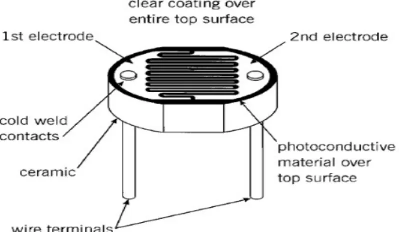
A suitable, cheap, simple and easy to connect photo sensor is the analog LDR, which is the most common in electronics.
Model layout
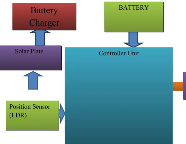
MOTORBATTERY
CAD layout
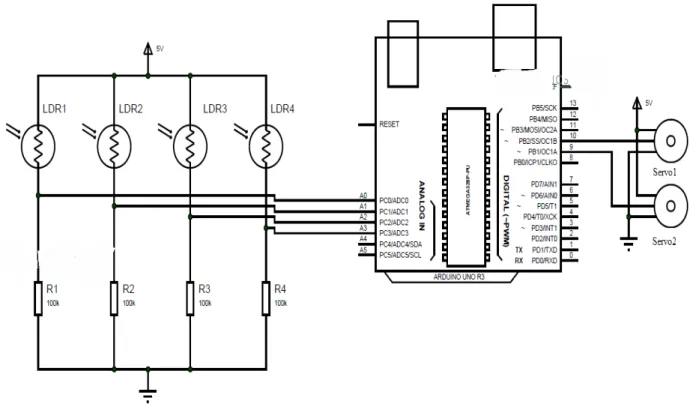
Circuit Diagram
- Assembly for the solar tracking system
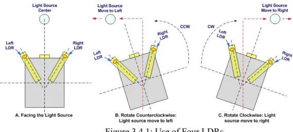
When applied to the actual situation, DC motor A will control the movement of the elevation axis of the solar tracker, and DC motor B will control the azimuth axis of the solar tracker. Therefore, the elevation axis must move counterclockwise and the azimuth axis must move clockwise, as shown by DC motor A and B in Figure 11, in order for all sensors to acquire the same light intensity. to achieve the same intensity of light, the height axis, which is the DC motor B, rotates clockwise.
On the other hand, azimuth axis controlled by DC motor A will rotate counterclockwise. In this case, the sun tracker should rotate its elevation axis clockwise and the azimuth axis should rotate counterclockwise. It compares the entire sensor to one fixed value of 15.1 lux which means that all the sensors receive the same light intensity.
LDR3 will receive the maximum amount of light to read numbers 1 and 2, so its output voltage is higher than the other sensor. Reading number 3 is taken at position 4, making the LDR1 and LDR2 values slightly higher than the other two sensors. Reading numbers 4 and 5 are taken at position 3, which eventually increases the output voltage of LDR2 and LDR3.
Reading numbers 6 through 15 is done at position number 5, with the light on top of the entire 4 sensor. Reading number 16 is where all four sensors achieved the same output voltage with some uncertainty for about 0.05 V, which is the difference with LDR2 and LDR4. Looking at readings 16 to 20, all output values reached the same peak, at about 4V.
This is the ideal position of the solar tracker with the panel perpendicular to the light source. Light source for reading number 17 to 20 is still in the same position as reading number 16. Two pairs of light dependent resistors (LDR) are used as sensors to track the exact position of the sun. One pair detects the position of the sun in the vertical axis, i.e.
Sensor (LDR)
- The concept of using four LDRs
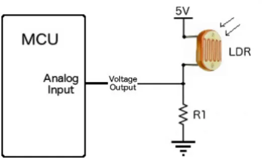
- Construction of Sensor (LDR)
The stable position is when the two LDRs have the same light intensity. When the light source moves, i.e. voltage changes are compared using the microcontroller's built-in comparator and a motor that is used to rotate the solar panel in a way that follows the light source. The value of the complementary resistor is chosen 19 so that the widest output range is achieved.
In this case Vi =- input voltage to the microcontroller R=Resistance of the [potentiometer which is 10K ] Vcc= Supply voltage to microcontroller and LDRs Vi=Input voltage to the microcontroller.
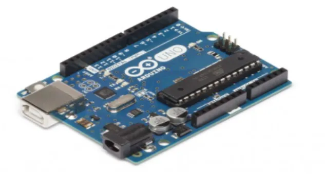
Microcontroller
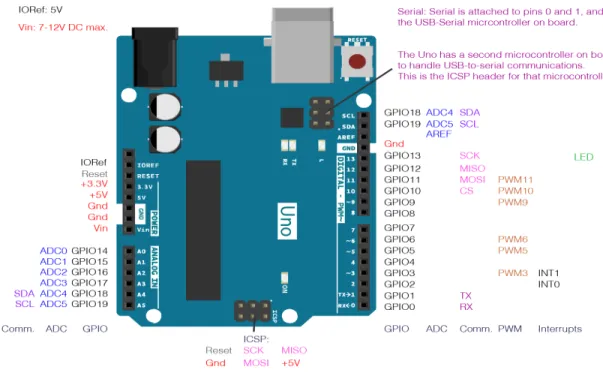
- Pin Configurations of Microcontroller
- Pin Descriptions
It has 14 digital input/output pins (6 of which can be used as PWM outputs), 6 analog inputs, a 16 MHz quartz crystal, a USB connection, a power connector, an ICSP header, and a reset button. It contains everything necessary to support the microcontroller; simply connect it to a computer with a USB cable or supply it with an AC-to-DC adapter or battery to get started. You can tinker with your Uno without worrying too much about doing something wrong, worst case scenario you can replace the chip for a few bucks and start over.
The Uno board and version 1.0 of the Arduino Software (IDE) were the reference versions of Arduino, now evolved into newer versions. The Uno board is the first in a series of USB Arduino boards and the reference model for the Arduino platform; for an extensive list of current, past, or obsolete boards, see the Arduino Boards Index. Select "Arduino/GenuinoUno from the Tools > Board menu (according to the microcontroller on your board) for details, see the reference and instructions. The ATmega328 in the ArduinoUno comes pre-programmed with a bootloader that allows you to load new code into it without using a programmer external hardware.
It communicates using the original STK500 protocol (reference, C header files). I can also bypass the bootloader and program the microcontroller via an ICSP (In-Circuit Serial Programming) header using an Arduino ISP or similar; see these instructions for details.[14]. The ATmega16U2 (or 8U2 on rev1 and rev2 boards) firmware source code is available in the Arduino repository. On Rev1 boards: Solder jumper connection on the back of the board (near Italy map) and then 8U2 reset.
On Rev2 or later boards: there is a resistor that pulls the 8U2/16U2 HWB line to ground, making it easier to put into DFU mode. You can then use Atmel's FLIP software (Windows) or the DFU programmer (Mac OS X and Linux) to load a new firmware. Or you can use the ISP header with an external programmer (overwriting the DFU bootloader).
The Uno differs from all previous boards in that it does not use the FTDI USB-to-serial driver chip. Instead, it features the Atmega16U2 (Atmega8U2 up to version R2) programmed as a USB-to-serial converter.
Power
Memory
Input and Output
TWI: A4 or SDA pin and A5 or SCL pin. Support TWI communication using the Wire library
Communication
Servo Motor
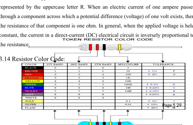
Resistance
Resistor Color Code
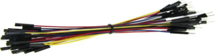
Wires
Cost Analysis
- Cost
Description of our Software
There is usually no need to edit make files or run programs on a command line interface. Although it is possible to build on command line if needed with some third party tools like Ino. The Arduino IDE comes with a C,C++ library called "Wiring". of the project of the same name), which makes many common input/output operations much easier.
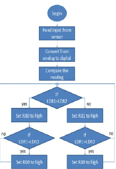
Flow Chart Diagram
Calculated output
Designed Output (2 January-2020, Dhanmondi area, fog day )
Comparison of two outputs
So we tried to make available an automatic solar tracking system that will increase the efficiency of the solar panel system. Although there are higher initial costs involved, we have tried to make the system cost effective. This is just the beginning, we can add different improvements to make the system more efficient so it will work. The solar panels using this system compared to the current system have many advantages.
In the current system, solar panels used are stationary, which gives less output and thus reduces efficiency. But by making use of tracker solar panels we can increase the efficiency of the solar system. Operator interference is minimal as the system is automated, increasing the efficiency of the stationary solar system.
DISCUSSIONAND CONCLUSION
Discussion
Conclusion
In addition to this designed tracking system can also be applied to solar thermal systems. Barsoun, "Implementation of a Prototype for a Traditional Solar Tracking System", UKSim Third European Symposium on Computer Modeling and Simulation, 2009, p. photovoltaic systems", IEEE Conference on Compatibility and Power Electronics, 2009, pp.
9] http://protorit.blogspot.com/2012/03/introduction-to-microcontroller.html [10] http://www.microchip.com/productselector/MCUProductSelector.html [11] http://massmind. org/techref/microchip/pages.htm.