Abul Bashar also thanks to the head of the Department of SU, Electrical & Electronic Engineering, Professor Dr. Voltage sensors are the input value for the Arduino and the LCD screen output the voltage and load status. Solar energy is one of the most promising renewable energy sources currently used globally to meet increasing demands for electrical energy.
Recent developments in the energy sector have shown that the solar energy market is one of the fastest growing renewable energy markets in the world. A solar PV power system requires reliable means of data acquisition of all electrical and meteorological data for condition monitoring and system performance evaluation. Acquiring such data has been capital intensive when modern equipment will be installed on site and there is a reliability concern over using satellite data instead of location data.
Solar Panel Monitoring Methods
Imagine a system where the user controls the devices and decides to take control by tuning his TV set to his favorite channel, turning on the cooling system, say the air conditioner, and turning some of the lights on or off . The method involves collecting data from one or more combined converters and displaying it on the display unit. And while a dedicated monitor is an extra cost, it allows you to monitor your system through the monitor.
With this method, the energy production information is sent to a router, which makes it available on the Internet. Since each user has a password-protected dedicated website, you can easily access the information. A good thing about this method is that you can access this data anytime remotely.
Objective
However, the card you will insert into the inverter, together with the router, will be an additional cost to the user.
Methodology
Goal of the Research Work
THEORY OF THE PROJECT
Introduction
Theory
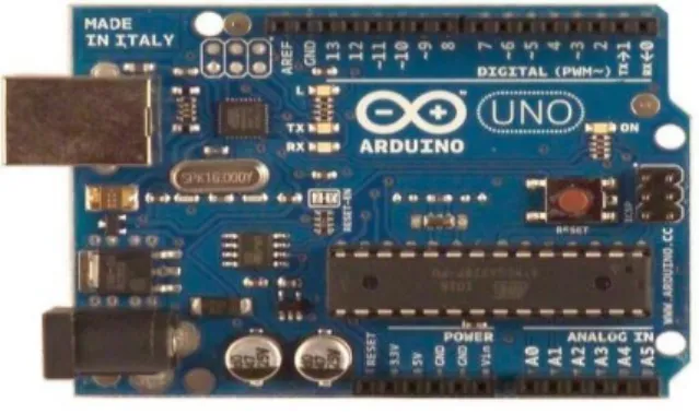
Arduino UNO
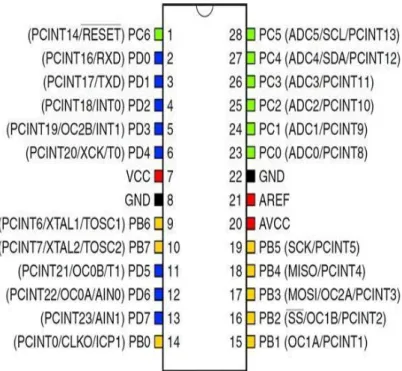
Reprinted from Datasheet of ATMega328 the internal architecture of the microcontroller is shown in Fig 2.3. The central processing unit (CPU) is the brain of the microcontroller that controls the execution of the program. As mentioned in section 2.1.2, the CPU is the brain of the microcontroller that controls the execution of the program.
The boot program section and the application program section are the two main sections of the program flash memory. The stack stores the return address of the program counter between interrupt and subroutine calls, which is allocated in the general data SRAM. Stack size is limited by total size and SRAM usage.
Specifications
The principle of executing instructions in the program memory is the one-level pipeline. The concept of prefetching the next instruction during the execution of an instruction enables the instructions to be executed every clock cycle and the program memory is in System Reprogrammable Flash memory. The Fast Access Register file contains 32 x 8-bit general purpose work registers with a single cycle access time resulting in a single cycle ALU operation.
The arithmetic and logical operations between the registers or between the constant and a register are supported by the ALU. The status register is updated to show information about the result of the operation after an arithmetic operation. The data SRAM is accessible through five different addressing modes supported in the AVR architecture, while the stack pointer is read/write accessible in the I/O space.
Features
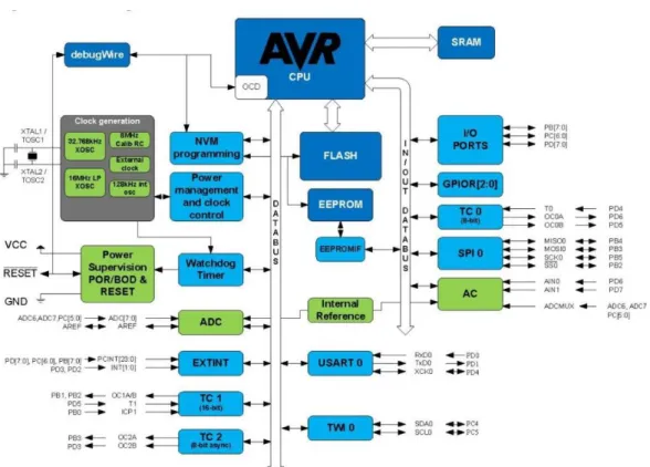
Microcontroller IC ATmega328p
- Power supply, inputs and outputs
- Digital inputs and outputs
- Analog inputs
- Detecting System
- Voltage Sensor
- Schematic of Voltage Sensor
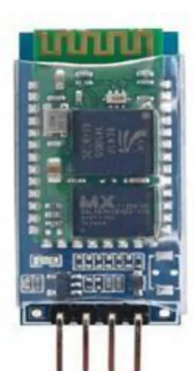
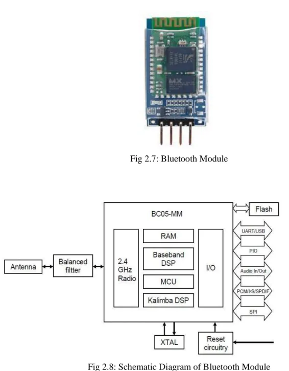
- Bluetooth Module
- Solar Panel
Either Arduino is supplied with USB connection or with an external power source (recommended with 7-12V), outputs are going to have a continuous voltage due to voltage regulators and stabilization capacitors present on the board. VIN: this is the input power supply that will have the same voltage as we supply the Arduino with the external power supply. 5V: power supply of 5V, this voltage can come from VIN pin and a voltage regulator or from the USB connection.
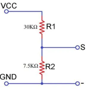
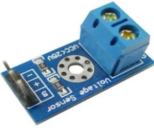
The voltage sensor is a simple module that can be used with the Arduino (or any other microcontroller with an input tolerance of 5 V) to measure external voltages that are greater than its maximum acceptable value, i.e. connected to the external voltage source, i.e. the S pin is the "Sense" pin and should be connected to the analog input of the Arduino.
The voltage sensor is basically a voltage divider consisting of two resistors with a resistance of 30 kΩ and 7.5 kΩ, i.e. the following figure shows a schematic of a voltage sensor module with an input voltage limit of 25 V. All devices have their advantages and disadvantages, but we will focus on the device that best suits our requirements.
There are certain features to consider when choosing the Bluetooth module for use. In Bluetooth 2.0, the signal transmission time of different devices is an interval of 0.5 seconds, so that the workload of the Bluetooth chip can be greatly reduced and more sleep time saved for Bluetooth. The panels are connected in series with a 1.4 kohm resistor to measure the voltage and calculate the current.
Externally, most PV modules use the MC4 type of connectors to facilitate easy weather connections to the rest of the system.
Features of LCD Display
Relay Module
A command is an instruction given to the LCD to perform a predefined task such as initializing it, clearing the screen, setting the cursor position, controlling the display etc.
Diode
Arduino IDE
Sketches are saved on the development computer as text files with an .ino file extension. The Arduino IDE provides a software library from the Wiring project that provides many common input and output procedures. The user-written code requires only two basic functions, to run the sketch and the main program loop, which are compiled and linked with the main() stub into an executable loop executable with the GNU toolchain, also included in the IDE distribution. .
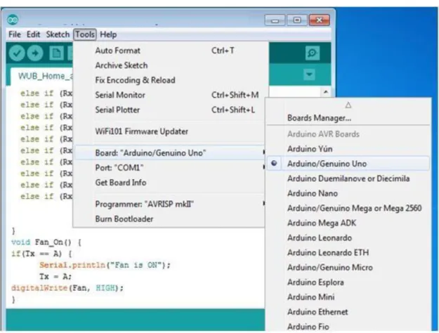
The Arduino IDE uses a program to convert the executable code into a hexadecimal-encoded text file that is loaded into the Arduino board using the board's firmware loader. To configure the software we need to use the ARDUINO IDE named arduino.exe. To configure this programmer with the computer, we need a USB cable, then check the serial port and select the programmer from the IDE platform, such as.
DESIGN & FEBRICATION
- Block Diagram
- Methodology
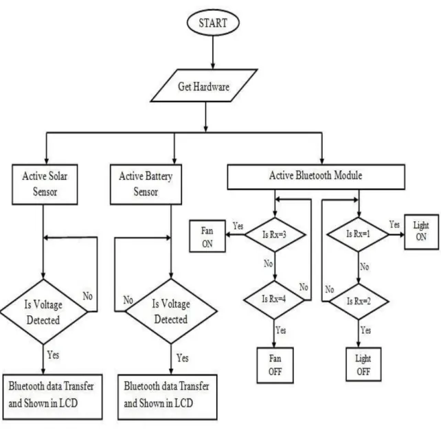
- Flow Chart
- Circuit Diagram
- Project Implementation
- Project Picture
- Software Configuration
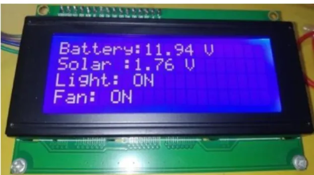
There are two voltage sensors, one is for solar panel and another is for battery. It is programmed and burned to the Arduino using the Arduino IDE software. If input data is 1, microcontroller turns on the light, if data is 2, microcontroller turns off the load, similarly, if data is 3, it turns on the fan, and when input data is 4, it turns off the fan.
In this project we connected three solar panels in series to generate voltage and charge the battery. In this project we use a 5V DC relay to control 12V DC light, both relays are connected to digital I/O pin 2 and 3. The Arduino Integrated Development Environment (IDE) could be a cross-platform application written in Java , and is derived from the process programming language IDE and also the Wiring projects.
It includes a code editor with options such as syntax highlighting, bracket matching, and auto-indentation, and is capable of compiling and uploading programs to the board with one click. The Arduino IDE comes with a code library called "Wiring" from the first Wiring project, which makes many common I/O operations much easier. 34;Arduino Uno from the menu Tools, Board (depending on the microcontroller on your board). The IC used as the ATmega328 on the Arduino Uno is pre-written with a bootloader that allows you to load new code into it without using an external hardware programmer.
The open source ARDUINO environment makes it easy to write code and upload it to the I/O board. To configure this programmer with computer we need a USB cable then check the serial port and select the programmer from Aruino-1.6.8 platform such as,. Specifies the data rate in bits per second (bauds) for data transmission in serial communication.
It prints the data to the serial port as ASCII text Serial.println(val,[format]). It prints the data to the serial port as ASCII text, but jumps to a new line. It returns the number of available bytes to be read by the serial port.
RESULT & DISCUSSION
- Introduction
- Result
- Application
- Advantages
- Costing
- Discussion
It can be used to generate electricity in remote places where power lines are not accessible. It can also be used for some household appliances like solar water heater or something like that. This device was then used to obtain solar PV current, voltage, power, temperature, pressure and light intensity.
The system can measure data from solar panels that can be used to evaluate the performance of the solar energy generated so that future energy generation can be predicted. Based on the measurement data, it was observed that the generation of solar PV energy is directly dependent on the solar radiation.
CONCLUSION AND FUTURE WORKS
Conclusion
Future Scopes of the Work
10] Chua Hock-Chuan (2015) Getting Started with Arduino (2016, October 30), available at https://www.ntu.edu.sg/home/ehchua/programming/arduino/Arduino.html. 11] Electrical 4U.com (2011) Light Dependent Resistor / LDR and working principle of LDR (2016, November 2) taken from http://www.electrical4u.com/light-dependentresistor-ldr-working-principle-of-ldr/ . Microcontroller-Based Traffic Light System for Intersection Control, Journal of Scientific and Technology Research, vol.
Matlab/Simulink model of solar PV array with MPPT perturbation and observation for maximizing PV array efficiency. Interfacing ACS712 Current Sensor with Arduino – Measuring Current with Arduino: Available online at https://www.electronicshub.org/interfacing-acs712-currentsensor-with-arduino/.
Appendix