©Daffodil International University i
IoT Based 6-DoF Robotic Hand to Monitor Patients in Hospitals
BY S.M.A. Ashraf ID: 181-15-1740
Mehedi Hasan ID: 181-15-2012
AND
Golam Rabbani Samim ID: 172-15-10071
This Report Presented in Partial Fulfillment of the Requirements for the Degree of Bachelor of Science in Computer Science and Engineering
Supervised By
Tajim Md. Niamat Ullah Akhund Lecturer
Department of CSE
Daffodil International University Co-Supervised By
Hasin Rehana Lecturer
Department of CSE
Daffodil International University
DAFFODIL INTERNATIONAL UNIVERSITY
DHAKA, BANGLADESH
DECEMBER 2020
©Daffodil International University ii
APPROVAL
This Project titled “IOT 6-DOF Robotic hand for hospital management”, submitted by
“S.M.A. Ashraf” and “Mehedi Hasan” & “Golam Rabbani Samim” to the Department of Computer Science and Engineering, Daffodil International University, has been accepted as satisfactory for the partial fulfillment of the requirements for the degree of B.Sc. in Computer Science and Engineering and approved as to its style and contents. The presentation has been held on 30 December 2020
BOARD OF EXAMINERS
(Name) Chairman
Designation Department of CSE
Faculty of Science & Information Technology Daffodil International University
(Name) Internal Examiner
Designation
Department of CSE
Faculty of Science & Information Technology Daffodil International University
(Name) External Examiner
Designation
Department of --- Jahangirnagar University
©Daffodil International University iii
DECLARATION
We hereby declare that, this project has been done by us under the supervision of Tajim Md. Niamat Ullah Akhund, Lecturer, Department of CSE Daffodil International University. We also declare that neither this project nor any part of this project has been submitted elsewhere for award of any degree or diploma.
Supervised by:
Tajim Md. Niamat Ullah Akhund Lecturer
Department of CSE
Daffodil International University Co-Supervised by:
Hasin Rehana Lecturer
Department of CSE
Daffodil International University
Submitted by:
S.M.A. Ashraf ID: 181-15-1740 Department of CSE
Daffodil International University
Mehedi Hasan Golam Rabbani Samim ID: 181-15-2012 ID: 172-15-10071 Department of CSE Department of CSE
Daffodil International University Daffodil International University
©Daffodil International University iv
ACKNOWLEDGEMENT
First, we express our sincere appreciation and gratitude to God Almighty for His divine blessing that enables us to successfully complete the final year project/internship.
We deeply respect and wish Tajim Md. Naimat Ullah Akhund, our sincere indebtedness. Senior Lecturer, Daffodil International University's CSE Department, Dhaka. Broad awareness & our supervisor's keen interest in carrying out this project in the field of "Field Name." It was possible to complete this project with his infinite patience, scholarly guidance, relentless encouragement, persistent and energetic supervision, constructive criticism, helpful advice, reading many inferior drafts, and correcting them at all times.
We would like to express our sincere gratitude to Dr. S.M Aminul Haque, Head of the CSE Department, for his kind assistance in completing our project, as well as to other faculty members and staff of Daffodil International University's CSE department.
We would like to thank our entire Daffodil International University course partner for taking part in this conversation while completing the work of the course.
Finally, our parents' continuous encouragement, and patients must be remembered with due regard.
©Daffodil International University v
ABSTRACT
This work results in a robotic arm which have 6 degrees of freedom movements. It will move its hand with servo motors and servo controller. Low cost micro controlling unit Arduino is used to control the system. Sensor array will be attached with the robotic arm by which this system will be able to collect the data. Then an LCD monitor will show the collected value to the patient. We made this system automated so that virus affected people may check their status and report without affecting other peoples.
Keywords:
6 DOF Robot Hand, Arduino, Servo Motor, IoT, Robotics.©Daffodil International University vi
TABLE OF CONTENTS
CONTENTS PAGE Approval………. iDeclaration………. ii
Acknowledgements……… iii
Abstract………... iv
CHAPTER CHAPTER 1: Introduction
1.1 Introduction………. 11.2 Motivation………... 2
1.3 Objective………. 3
1.4 Expected Outcome………... 4
1.5 Report Layout.……… 5
CHAPTER 2: Literature Review
2.1 Introduction………. 62.2 Background Study………... 7
CHAPTER 3: Requirement Analysis and Methodology
3.1 Introduction………. 83.2 Project Research Subject and Instrument……… 9
©Daffodil International University vii
3.2.1: Servo motor………. 10
3.2.2: Servo Controllers ……… 11
3.2.3: Arduino UNO R3 ……… 12
3.2.4: Breadboard………... 13
3.2.5: Wires……… 14
3.2.6: Battery………. 15
3.2.7: Battery charger………... 16
3.2.8: Variable Resistance ……… 17
3.2.9: DHT11 sensor ………... 18
3.2.10: LCD 16x2……….... 19
3.2.11: 6 DOF Robot Arm……….... 20
3.2.12: C# Programing Language ………... 21
3.2.13: 6 DOF Robot Hand Circuit Diagram……….... 22
3.2.13: 6 DOF Robot Hand Flow Chart………... 23
3.4 Algorithm ………... 24
CHAPTER 4: Result and Outcome
4.1 Temperature and Humidity Result ………. 254.2 Testing………. 26
4.3 Finally Outcome of System………. 27
4.4 Final View of Robot……… 28
4.5 Limitation……… 29
©Daffodil International University viii
CHAPTER 5: Future Work and Conclusion
5.1 Future Work………. 30
5.2 Conclusion………. 31
5.3 References………... 32
©Daffodil International University ix
LIST OF FIGURES
FIGURES PAGE NO
Figure 1.1: Introduction 1
Figure 3.2.1: Servo motor 3
Figure 3.2.2: Servo Controllers 4
Figure 3.2.3: Servo motor controllers’ work 5
Figure 3.2.4: Servo Motor Control using 6
Figure 3.2.5: Arduino UNO R3 7
Figure 3.2.6: Breadboard 8
Figure 3.2.7: Wires 9
Figure 3.2.8: Battery 10
Figure 3.2.9: Battery charger 11
Figure 3.2.10: Variable Resistance 12
Figure 3.2.11: DHT11 sensor 13
Figure 3.2.12: LCD 16x2 14
Figure 3.2.13: 6 DOF Robot Arm 15
Figure 3.2.14: C# Programing Language 16
Figure 3.2.15: 6 DOF Robot Hand Circuit Diagram 17
Figure 3.2.16: 6 DOF Robot Hand Flow Chart 18
Figure 4.1.1: Temperature and Humidity Result One 19 Figure 4.1.2: Temperature and Humidity Result Two 20
Figure 4.4.1: Final look Side One 21
Figure 4.4.2: Final look Side Two 22
Figure 4.4.3: Final look Side Three 23
©Daffodil International University 1
CHAPTER 1 Introduction
1.1 Introduction
This is a robotic arm featuring a robot. This robot is able to detect gestures from humans, be able to move towards humans, be able to diagnose human diseases, detect human appearance through cameras, and diagnose diseases, and convert it into commands. This robot can move 360 and works like image processing. A special feature is that the virus detector can work in areas where people cannot work easily, where humans can't go, robots can go and work, it can work very easily there.
1.2 Motivation
1. By implementation this robotic hand we want to digitalize the hospital system.
2. Time consume will be reduce.
3. this Robot is echo friendly.
1.3 Objective
1. Collect sensor data from patients and send those in the could database.
2. Doctors can reduce physical effort and detect human pulse and body temperature.
3. Reduce time and expense.
4. This Robot work virus detected area and Communicative with patient friendly.
1.4 Expected Outcome
1. The robot is capable of six-degree movement.
2. The robot checks the patient's body temperature and humidity.
3. The robot is much needed in the hospital for the COVID-19 virus.
4. This robot can be used by doctors and nurses so that no doctor or nurse is infected with the virus.
5. We have to improve our country. Patients will take less time and less Trouble. We will be protected from different types of viruses.
©Daffodil International University 2 1.5 Report Layout
The main target of this robotic hand is to give proper treatment timely, and the safe of patient life.
It can detect vital signs and monitor patient conditions.
Chapter – 1
Introduction, Motivation, Objective, Expected Outcome
Chapter – 2
Literature Review, Introduction, Project Paper Study Related Work
Chapter – 3
Requirement Analysis and Methodology, Introduction, flowchart, Algorithm
Chapter – 4 Results and Outcome
Chapter – 5 Future Work, Conclusion
©Daffodil International University 3
CHAPTER 2 Literature Review
2.1: Introduction
In this world robots and robotic device are very useful product for our daily life. We cannot think about a day without this kind of device. In every sector Robotic Arm is a substance service product. Robot can work 24 hours without any rest. It can also work any different places in dangerous situation like manufacturing, assembly and packing, transport, space exploration, war zone, laboratory, hospital and virus infected area.
Robotic is research area of computer science and engineering. It became faster by using artificial intelligence. All kind of robots are a great tool to help mankind. After studding some paper, we become know that.
2.2: Background study
In order to create six degrees of freedom of movement in a robotic arm, the authors [1]
suggested mechanism design and kinematic simulation, allowing its motion to be effectively controlled. This system's functionality is based on parallel mechanisms. From the establishment of some 4 bar linkage mechanisms in a parallel combination, they have used this mechanism in particular. Based on this mechanism, they developed a CAD model for an operational 6 DOF robotic arm and finally supplied the kinematic mechanism and finally supplied the kinematic relationships between the space of the actuators and the space of the robot's joints with this mechanism. They include the results of the kinematic simulation in MATLAB Mechanics software of the robotic arm's work and different graphs showing the simulation results. The authors [2] proposed the development and preliminary evaluation of a novel robotic-assisted bi-lateral hand grasping rehabilitation training method using a novel robotic exoskeleton and on-line muscle contraction measurement by EMG. The proposed device is designed to estimate the grasping force exerted by the non-paretic hand via EMG signals and to pass the same force through an EMG-driven hand exoskeleton to the paretic hand in real-time.
©Daffodil International University 4 In both passively guided or actively cooperating situations, the device may provide assistance for hand grasping and finger extension. To test the viability of use in stroke recovery, system efficiency in replicating the gripping force, and successively with two- stroke patients. The authors [3] suggested the use of the Adaptive Neuro-Fuzzy Inference method to reduce the computational solving time of the Robotic Arm verse kinematics. If there is undefined external noise in the device, ANFIS is beneficial. For production processes using Robot Weapons, this approach is used. Here the authors used 3d CAD model modeling tools, Solid Works, and MATLAB. The authors [4] suggested a robotic hand-arm teleoperation device with a novel data glove called YOBU, which can simultaneously obtain human gestures from both the arm and the hand. The data glove proposed is built to be secure, lightweight, and portable. A robotic arm-hand teleoperation device using a human arm-hand with a data glove is proposed by the authors of this paper. Two communication levels, a standard Rs-232, and network communication are used here to transmit the commands. Like imitating the movement of the human arm and hand, the robotic hand-arm can be teleoperated. The robotic hand and robotic arm can be teleoperated by the operator via the suggested teleoperation method.
Authors [5] build a 6 DOF robotic arm for the kinematic models and evaluate their workspace. In order to achieve some reachable position, the proposed model makes it possible to control the manipulator. Here, robotic manipulators with several degrees in one or more joints have a high degree of freedom (DOF). For robot simulation, they use inverse kinematics. A robotic arm that can perform multi-functional tasks is proposed by the authors [6]. The Arduino Mega 2560 microcontroller and a 3D vision camera are used here. The method is based on two separate algorithms: Algorithm 1 and Algorithm 2.
Algorithm 1 is the red color detection algorithm used to classify the red color detection object used to describe the red color object. Algorithm 2 is the object location recognition algorithm that was also used after Algorithm 1. in the robotic arm. A new robotic hand specifically designed for dexterous spatial manipulation is proposed by the Authors [7].
Instead, the suggested mechanism is based on the Stewart platform parallel manipulator's non-anthropomorphic hexapod structure.
©Daffodil International University 5 They propose a new hand design based on parallel mechanisms that use three,2-DOF parallel linkage fingers to achieve dexterous 6 DOF manipulation comparable to a Stewart platform. The hand utilizes an underactuated differential tendon drive from a single "grasp" actuator to the three fingers of the hand to route tension equally. The Authors [8] submitted a two-loop parallel system consisting of three 6 DOF arms with potentiometers on the first three joints of each arm for the autonomous kinematic calibration of the RSI 6 DOF hand controller. The closed-loop approach is extended in this paper to a multiple loop mechanism, the hand controller of the RSI 6 DOF. This hand controller is a master of positioning, which includes manipulation of a handle in a roll, pitch, and yaw range. There are potentiometers at the joint of the shoulder and elbow, but there is no sense of the wrist joints. The authors [9] suggested a Gazebo-based system for robotic weapons in a practical physical environment. The Parallel Axis Theorem is used to measure the moment of inertia in relations. The essential parts of the framework are the joint controllers and the route planning algorithm. Given its simpler hardware abstraction, ROS is chosen to organize task architecture. The majority of Gazebo simulation research mainly uses the official model and the purpose of the implementation of the current system are limited. This paper presents a general simulation method for setting up six joint manipulator controls. They used MOI to estimate each relation. A new 6 DOF cable-driven manipulator for handheld robotic tasks is proposed by the authors [10]. The arm is optimized based on a pair of tendon approaches to maximize movement speed and configuration space while reducing the total arm mass. To design optimal link geometry to optimize link mass, they propose a space carving approach. The design improves and reduces the necessary number of actuators to one per DOF on similar non- handheld tendon-driven manipulators. It was optimized for a long arm’s length so that it could reach deep within a reactor and there was no primary concern about the speed of movement of the end effector. The primary benefit of their architecture is that all the engines are coupled. Authors [11] present an approach to assistive robotics using a 6 DOF Robotic Arm, an exotic spot sensor, and a Kinect camera, based on a brain- computer interface (BCI) on the (SSVEP).
©Daffodil International University 6 The aim of developing a robotic assistant for disabled or movement-restricted users is to improve the quality of life of those individuals. The Authors [12] identify a new approach and device developed for upper extremity prosthesis applications. EMG signals are used here, and their movements are monitored by a set of ultrasonic and infrared sensors.
Knowledge about the robot environment is generated by a multisensory system.
Ultrasonic sensors and infrared sensors are the core of the multi-sensor system. The robotic arm is a model of a promising prosthetic arm and MATLAB/Simulink has developed and tested its control system and the methods used. After reviewing the documents, we became aware of the implementation of 6 DOF Robotic Arm. The robotic arm will do a lot of work using 6 DOFs. A 6 DOF Robotic Arm is operated by the authors [5] and allows for any reachable position to be achieved. A 6 DOF Robotic Arm for handheld use was implemented by the author [10].
©Daffodil International University 7
CHAPTER 3
Requirement analysis and Methodology
3.1 Introduction
This is a research paper that is used to select strategies and observe the process. Below
are some details about this research equipment
3.2 Project Research Subject and Instrument Most of the patient information has been written on the paper. The title of this paper is
IoT 6 DOF Robot Hand for Hospital Management. We know that when a person is injured, people go to the hospital and there is no treatment. Many patients do not have access to nurses and doctors due to the current epidemic situation, which is why we have come up with the idea of creating a robotic hand for hospitals. Which can help the patient. We have used these components to implement our project.
1. Servo motor 2. Servo Controllers 3. Arduino UNO R3 4. Breadboard 5. Wires 6. Battery
7. Battery Charger 8. Variable Resistance 9. DHT11 sensor 10. LCD 16x2
11. 6 DOF Robot Arm 12. C# Programing Language
13. 6 DOF Robot Hand Circuit Diagram 14. 6 DOF Robot Hand Flow Chart
©Daffodil International University 8 In this chapter we will discuss about required particles of our project. The main part that we have used here Servo motor, Servo controller, Arduino UNO R3, Battery as Battery charger, Joystick, DHT11 sensor, wires. We also use C# programming language. The description all of equipment we will discuss elaborately
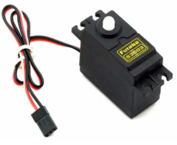
Servo motor
Figure 3.2.1: Servo motor
The main conceptual Servo Motor is shown in Figure 3.2.1: - Our servo motor is used in application like auto machine technology device and it is an electrical device. This motor is used for small children’s toys such as car, planes etc. and many more devices are used.
It works at a quality and accrued speed. This is servo motor is connected to a sensor. The price of this servo motor is lower than servo motor is lower than the market price. We are using servo motors to attach the robot to the hand.
Two-power servo motor type: -
One Servo Motor DC
Two AC Servo engines
©Daffodil International University 9 Three lessons from our Servo Motor Working Mechanism
first servo motor Controlled Device
second servo motor Output sensor
thread servo motor Feedback system
Servo motor of specification: -
Servo motor Operating Voltage is + 5v. Hey, its weight is 9gm and operating speed is 0.1s / 60 and rotation 0 ° -180 °. It is a good servo motor.
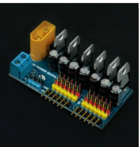
Servo Controllers
Figure 3.2.2: Servo Controllers
The main conceptual Servo Controllers is shown in Figure 3.2.2: - We will be able to control the 6 DOF robot hand using this servo motor control. This servo motor control works in such a way that the command and the output and input of the motor work while operating. It is an input and output device. The main control is power supply and speed control unit so we will use robot hand.
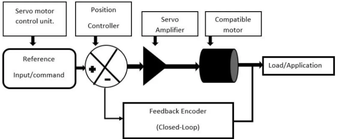
©Daffodil International University 10 How do servo motor controllers work?
Figure 3.2.3: Servo motor controllers’ work
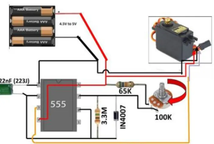
Servo Motor Control using: -
Figure 3.2.4: Servo Motor Control using
Servo motor controllers of specification: -
It has 12 servo connectors. It has 12 micro servos and 6 medium servos. It has 2s Lipo 8- volt input peak output current 1A and 3s Lipo 12-volt input 700mA.
©Daffodil International University 11
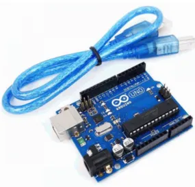
Arduino UNO R3
Figure 3.2.5: Arduino UNO R3
The main conceptual Arduino UNO R3 is shown in Figure 3.2.5: - Basically, it is an Arduino UNO R3 microcontroller board. It is an open source platform for input and output pin boards. It is used in applications and software. Its market value is very high. It has an advantage that programs can be added, deleted and programs can be updated. We are using the Arduino UNO R3 microcontroller board for this 6 DOF robot hand.
Arduino UNO R3 of specification: -
Our Arduino voltage limit is 6v to 20v and it has an In-Built LED. And its operating voltage is 5 volts and its SRAM is 2KB and EEPROM is 1 KB. Its flash memory is 32 KB and 0.5 KB memory is used.
©Daffodil International University 12
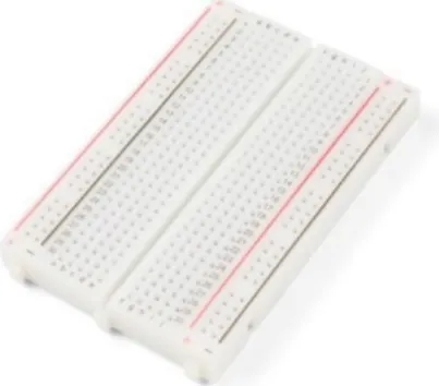
Breadboard
Figure 3.2.6: Breadboard
The main conceptual Breadboard is shown in Figure 3.2.6: - We are using a board with 400 pins attached. There is no soldering. This is a hassle-free board that can be used to open and connect each of the wires. It can be used for a long time.
Breadboard of specification: - 840 contact points
320 tie points
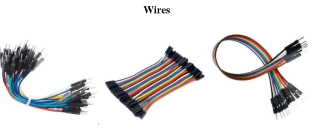
Wires
Figure 3.2.7: Wires
©Daffodil International University 13 The main conceptual Wires is shown in Figure 3.2.7: - This is a connecting wire with which we can connect the equipment of our robot. It basically has various jumper wires equal to its two sides so it has to do both the negative and the positive itself. Its market price is low.
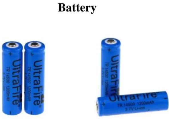
Battery
Figure 3.2.8: Battery
The main conceptual Battery is shown in Figure 3.2.8: - We need an electrical DC power supply to run our device. We get power on 14500 rechargeable Lithium batteries. It helps to run the device. I recharge it using a rechargeable battery rechargeable battery case. It can be recharged 600 times and is more effective.
Battery charger
Figure 3.2.9: Battery charger
©Daffodil International University 14 The main conceptual Battery charger is shown in Figure 3.2.9: - Our battery Charger case has AC power as input (250v) and it is a converter. We convert this converter from AC power to DC power to strengthen to rechargeable battery.
battery Charger of specification: -
Input 250v
Multiple time can use
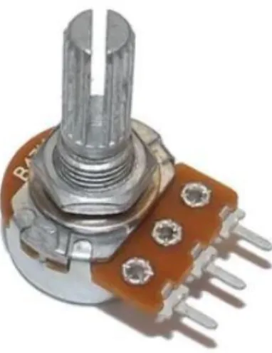
Variable Resistance
Figure 3.2.10: Variable Resistance
The main conceptual Joystick is shown in Figure 3.2.10: - Variable Resistance is basically an input device it is used for video games and kids toys like car, plane etc. it is used as touchpad. Basically, it is USB or serial port connection so we can control our robot with it.
©Daffodil International University 15
DHT11 Sensor
Figure 3.2.11: DHT11 Sensor
The main conceptual DHT11 Sensor is shown in Figure 3.2.11: - The function of this DHT11 sensor is to complex the temperature and humidity sensor with a digital signal output. This sensor ensures a high reliability using temperature and humidity technology in digital signaling and acquisition techniques. This sensor incorporates resistance humidity measurement and temperature it combines with a high efficiency 4 – bit microcontroller it is used as a great quality fast process anti - interference capability and cost effectiveness.
Definition of pin: -
GND = Negative Power = DHT11 sensor (Ground)
DHT11 sensor VCC = 3.5-5.5V DC Power Supply
DHT11 DOUT sensor = Serial Data, a single bus DHT11 Specification Sensor: -
Power supply for the DHT11 sensor: DC 3.5 to 5.5V
©Daffodil International University 16
Duration of DHT11 sensor sampling: more than 2 seconds
Sensor DHT11 Resolution: 16Bit
Repeatability: ±0.2°C ⁇ DHT11 sensor Repeatability: ±0.2°C
Scope of the DHT11 sensor: 25 °C ±2 °C
DHT11 sensor Response time: 1 / e (63 percent) 10S Response time:
LCD 16x2
Figure 3.2.12: LCD 16x2
The main conceptual LCD 16x2 is shown in Figure 3.2.12: - Our 16 × 2 LCD all kinds of CMOS / TTL devices. It has a 32-digit display screen. I am using this display to provide information to our 6 DOF robot. This display supports custom signs and designs. This includes a data pin and a command pin. This is an input and output pin.
LCD 16x2 sensor of specification: -
LCD – Liquid Crystal Display.
Our LCD two registers.
This is an LCD display in 5 x 7-pixel matrix.
Our LCD display Screen Dimensions is 64.5 mm x 16mm
©Daffodil International University 17
6 DOF Robot Arm
Figure 3.2.13: 6 DOF Robot Arm
The main conceptual 6 DOF Robot Arm is shown in Figure 3.2.13: - We have 6 servo motors in the use of 6 Degrees of Freedom Mechanical Robot Hand. Hey, sensors have been added to the information will be displayed on our LCD display.
6 DOF Robot Arm of specification: -
6 servo motors have been added to it.
There is a DHT11 Sensor add.
3.2.14 C# programming language: -
We are using temperature and humidity using C# Programming Language. This programming language will have Arduino UNO R3 microcontroller board setup and from there our 6 DOF Robot Hand will work.
©Daffodil International University 18
6 DOF Robot Hand Circuit Diagram
Figure 3.2.15: 6 DOF Robot Hand Circuit Diagram
The main conceptual circuit diagram is shown in Figure 3.2.15: - First go to Arduino to get power from the battery. And receive data from Arduino Variable Resistance, DHT11 sensor and LCD display 16x2. Then it sends data to Arduino and receives data from Arduino to servo controller and from there it receives data from robotic arm. It has 6 servo motors and it has a sensor added. And it will control the joystick. And give the information to the servo controller and he will send it to Arduino and from here the LCD display will go 16x2 and show the data.
©Daffodil International University 19
6 DOF Robot Hand Flow Chart
Figure 3.2.16: 6 DOF Robot Hand Flow Chart
The main conceptual 6 DOF Robot Hand Flow Chart is shown in Figure 3.2.16: - First we will start 6 DOF Robot Hand and power on Arduino takes power and collect data from Variable Resistance and DHT11 sensor send data to the servo controller and Move the robot hand and set the sensor if sensor data is received then Arduino takes power and collect data from joystick and DHT11 sensor and if data is received then print the value on LCD then the robot will stop.
©Daffodil International University 20 3.4 Algorithm
We are using an algorithm in this robot which we are using C# Program Language to control and it will be given Arduino setup and it will control the robot. The simplified algorithm of the system is as follows:
Step_1: - Start Step_2: - Power on
Step_3: - Arduino power and collect data from joystick and DHT11 sensor Step_4: - Send data to servo controller
Step_5: - Move robot hand and set the sensor Step_6: - Sensor data received
Step_7: - Print value on LCD Step_8: - Stop
©Daffodil International University 21
CHAPTER 4
Result and Outcome
4.1 Temperature and Humidity Result
We have got the experimental results of this robot which has a sensor attached to the robot. that sensor checks the human body temperature and humidity and shows the information on our LCD 16x2 display and it can be controlled via a servo controller and Variable Resistance, it can be moved left, right, up and down 6 degrees.
Figure 4.1.1: Temperature and Humidity Result One
©Daffodil International University 22 The main conceptual Temperature and Humidity Result One is shown in Figure 4.1.1: - by using we have got the result successfully.
We have used C Program Language in it and we have been successfully in using this program.
Figure 4.1.2: Temperature and Humidity Result Two
The main conceptual Temperature and Humidity Result Two is shown in Figure 4.1.2: - the temperature and humidity results from the human body that we use have been successfully.
©Daffodil International University 23 4.2 Testing
We tested part of our system and get results. We get the results of human body temperature and humidity from our robot’s sensors.
4.3 Finally Outcome of System.
1. The robot is able to give information about the patient’s body temperature and humidity.
2. It has 6-degree movement power.
3. This robot is controlled by Variable Resistance and servo controller.
4. It has 6 servo motors.
5. It has a DHT11 sensor and LCD 16x2 display.
4.4 Final view of robot
Figure 4.4.1: Final look Side One
©Daffodil International University 24 Figure 4.4.2: Final look Side Two
©Daffodil International University 25 Figure 4.4.3: Final look Side Three
4.5 Limitation
1. The mechanism is not water proof. It can be disabled when the device is in contact with water.
2. Any time sensor or other aspect of this project may be completely dependent on technology.
3. The robot should be meticulously maintained. It can't be a career otherwise.
©Daffodil International University 26
CHAPTER 5
Future Work and Conclusion
5.1: Future work
Robots are very popular in our modern times and robots are used in many factories. This robot needs to be used in hospitals because now there is a virus called KOVID-19 in the world. when a patient is infected with the KOVID-19 virus, they go to the hospital and there is treatment. This is why we used this robot for the hospital because it will not infect nurses and doctors with any kind of virus. This robot has a sensor that will check the patient’s body temperature and humidity and give it to the doctor or nurse. The doctor or nurse will control this robot with a Variable Resistance.
5.2: Conclusion
This project is IoT based on 6 DOF robot hand which has 6 servo motors, Variable Resistance, DHT11 sensor, and Arduino micro-control and it has a servo controller.
Patient information can be obtained through sensors. And the robot can be controlled through the Variable Resistance. When we move the robot up and down left and right, the robot moves. If we use this robot in the hospital, doctors and nurses will lose a lot of work. We can say that our project has been effective for the patients and doctors and nurses in the hospital.
©Daffodil International University 27
References
[1] Mohsen Shahhosseini, Rambod Rastegari, Roozbeh Abbasi, Mechanical Engineering Department, School of Engineering, University of Islamic Azad, Parranda Branch, Parand, Iran International Journal of Robotics and Automation (IJRA) Vol. Number 5, No. 1, March 2016.
[2] Daniele Leonardis, Michele Barsotti, Massimiliano Solazzi, Claudio Loconsole,
Marco Troncossi, Claudio Mazzotti, Vincenzo Parenti Castelli, Caterina Procopio+, Giuseppe Lamola+, Carmelo Chisari+, Massimo Bergamasco, Antonio Frisoli, PERCRO TeCIP Laboratory Institute Scuola Superiore Sant'Anna, DIN, Department of Industrial Engineering, University of Bologna, Department of Neuroscience, Unit of Neurorehabilitation, University of Pisa.
[3] Karna Patel, International Journal of Research in Science and Engineering, Volume 7, ISSN 2229-5518, Issue 1, January-2016.
[4] Bin Fang, Di Guo, Fuchun Sun, Huaping Liu, Yupei Wu Study sponsored by China National Science Foundation for Young Scientists (Grant No.61503212), China NSF Project Main Instrument, China Principal Investigator, and China National Foundation for Natural Science (Grant No. 61327809.
[5] Jamshed Iqbal, Raza ul Islam, and Hamza Khan Electrical and Electronics Engineering Journal of Canada Vol. 3, No. 6, July 2012 https:/www.researchgate.net/publication/2806430855
[6] Qiang Wang, Vishal Kumar, Wang Minghua, Syed Rizwan, SM Shaikh, Xuan Liu
Monitor Science and Engineering Department, Harbin Institute of Technology Harbin, from China
[7] Connor M. McCann, IEEE Student Member, and Aaron M. Dollar, Senior Member, IEEE 2017 IEEE/RSJ International Intelligent Robots and Systems (IROS) Conference, Vancouver, BC, Canada, September 24-28, 2017.
[8] John M. Hollerbach, IEEE Senior Member, and David M. Lokhorst, IEEE ROBOTICS AND AUTOMATION TRANSACTIONS, VOL. NO. 11, NO. 3. 1995 JUNE
[9] Zexin Huang, Fenglei Li, Lin Xu*, 6 DOF Robotic Arm Focused on Gazebo Modeling and Simulation, 2020 6th International Conference on Control, Automation and Robotics
©Daffodil International University 28 [10] Inverse Kinematics and Construction of a Novel 6-DoF Handheld Robot Arm by Austin Gregg-Smith and Walterio W. Mayol-Cuevas
[11] Camilo Andrés Cáceres1, João Maurício Rosário2, Dario Amaya 3 Mechanical Engineering International Review (I.RE.M.E.), Vol. For xx, n. x HWT/http/www.praiseworthyprize.org/jsm/index.php?
Journal=ireme&page=article&op=view&path percent 5B percent 5D=190477path percent 5B percent 5D=190477
[12] Czech Technical University in Prague, Patrik Kutilek, Jan Hybl, Jan Kauler, and Slavka Viteckova, Faculty of Biomedical Engineering, nam. Sitna 3105, 272 01 Kladno, Czech Republic, [email protected], [email protected], [email protected], [email protected] https:/www.researchgate.net/publication/261386784