Medicare Plus
Submitted by:
Saiful Islam ID: 151-35-865
Batch: 16th
Department of Software Engineering Faculty of Science & Information Technology
Mehedi Hasan Shakil ID: 151-35-847
Batch: 16th
Department of Software Engineering Faculty of Science & Information Technology
Supervised by:
Syeda Sumbul Hossain Senior Lecturer
Department of Software Engineering Faculty of Science & Information Technology
A project submitted in partial fulfillment of the requirement for the degree of Bachelor of
ACKNOLEDGEMENT
At first, we are grateful to The Almighty Allah for making us eligible to complete this project. Then we would like to thank our supervisor Syeda Sumbul Hossain, Senior Lecturer, Department of Software Engineering. We are extremely grateful and indebted to her expert, sincere and valuable guidance and encouragement extended to us.
We wish to express our sincere thanks to Dr. Touhid Bhuiyan, Professor & Head of Software Engineering department for his constant encouragement.
We would also like to thank Dr. Abul Ahsan Didar, Professor & Head, Cancer-Medical Oncology, Shaheed Suhrawardy Medical College and Hospital, who helped us with his valuable time, resource and requirements for this project.
Last but not least, we would like to thank our parents, for their unconditional support, love and without this we would not have come this far.
Above all, we would like to thank to The Almighty Allah for giving me strength to complete this project.
Executive Summery
Medicare Plus is basically an android application. Anyone can use this by phone. The system builds for patients who have face various medical procedures problems and for doctors whose also have face same problems. For those people who are very busy in their life and sometimes it is hard to maintain easily those procedures. It is a system, eligible for Patient to conduct appointment easily, manage prescriptions and documents easily, manage taken medicine consuming. Again, helpful for doctor to manage appointments, conduct daily medicine consuming, prescribe according to patient‟s documents. The work plan could be realized step by step as it was proposed. The highly qualified expert group contributed, in addition to collecting and screening the relevant documents, by making some methodological adjustments and by participating actively in the building process.
Table of Contents
ACKNOLEDGEMENT ... iii
Executive Summery ... iv
Chapter 1 ... 1
Introduction ... 1
1.1. Project Overview ... 1
1.2. Project Purpose ... 1
1.2.1. Project Background ... 1
1.2.2. Beneficiaries and Benefits ... 1
1.2.3. Project Goals ... 2
1.3. Stakeholders ... 2
1.4. Proposed System Model... 2
1.4.1. Agile-Model ... 2
1.4.2. How we used Agile ... 3
1.5. Project Schedule ... 4
1.5.1. Gantt Chart ... 4
1.5.2. WBS Planning for Development Phase ... 4
Chapter 2 ... 6
Software Requirements Specification ... 6
2.1. Requirement Specification ... 6
2.2. Data Requirements ... 6
2.3. Performance Requirements ... 7
2.3.1. Speed and Latency Requirements ... 7
2.3.2. Precision and Accuracy Requirements ... 7
2.3.3. Capacity Requirements ... 8
2.4. Dependability Requirements ... 8
2.4.1. Reliability Requirements ... 8
2.4.2. Availability Requirements ... 8
2.4.3. Robustness or Fault-Tolerance Requirement ... 9
2.5. Maintainability and Supportability Requirements ... 9
2.5.1. Maintenance Requirements ... 9
2.5.2. Supportability Requirements ... 9
2.5.3. Adaptability Requirements ... 9
2.6. Security Requirements ... 10
2.6.1. Access Requirements ... 10
2.6.1. Integrity Requirements ... 10
2.6.2. Privacy Requirements ... 10
2.7. Usability and Human-Interaction Requirements ... 11
2.8.1. Appearance Requirements ... 11
2.8.2. Style Requirements ... 11
Chapter 3 ... 12
System Analysis ... 12
3.1. Use Case ... 12
3.2. Use Case Description ... 13
3.2.1. Authenticate User ... 13
3.2.2. Create Appointment ... 14
3.2.3. Approve Appointments ... 15
3.2.4. Save documents ... 16
3.2.5. View Patients ... 17
3.2.6. Manage Medicines... 18
3.2.7. Set Alarm Notifications ... 19
3.3. Activity Diagram ... 20
3.3.1. Activity Diagram for Patient ... 20
3.3.2. Activity Diagram for Doctor ... 21
Chapter 4 ... 22
System Design Specification ... 22
4.1. Sequence Diagram ... 22
4.1.1. System Sequence Diagram: Authenticate User: Patient ... 22
4.1.2. System Sequence Diagram: Authenticate User: Doctor ... 22
4.1.3. System Sequence Diagram: Create Appointment ... 23
4.1.4. System Sequence Diagram: Approve Appointments ... 23
4.1.5. System Sequence Diagram: View Patient List ... 24
4.1.6. System Sequence Diagram: Manage Medicine: Doctor ... 24
4.1.7. System Sequence Diagram: Manage Medicine: Patient ... 25
4.1.8. System Sequence Diagram: Manage Medicine Timer ... 25
4.1.9. System Sequence Diagram: Upload Documents ... 26
4.1.10. System Sequence Diagram: View Documents ... 26
4.1.11. Sequence Diagram: Patient ... 27
4.1.12. Sequence Diagram: Doctor ... 28
4.2. Data Flow Diagram ... 29
4.2.1. DFD Level 0 ... 29
5.1.1. Patient Profile ... 33
5.1.2. All Doctors List ... 33
5.1.3. Doctor‟s Profile ... 34
5.1.4. Appointment Requests and Approve Procedures ... 34
5.1.5. Input Medicines... 35
5.1.6. Medicines Consuming Times ... 35
Chapter 6 ... 37
Development Tools and Technologies ... 37
6.1. User Interface Technologies ... 37
6.2. Implementation Technologies ... 37
6.2.1. Java SE 11 (18.9 LTS)... 37
6.2.2. Android.Content.Pm.PackageManager ... 37
6.2.3. Android 8.1 Framework ... 37
6.2.4. Firebase ... 37
6.2.5. Google Cloud Vision API ... 37
6.3. Platform and Environment ... 37
6.3.1. Hardware ... 37
6.3.2. Tools ... 37
6.3.3. Version Control ... 38
Chapter 7 ... 39
System Testing ... 39
7.1. System Testing ... 39
7.2. System Testing ... 39
7.4. Test Case ... 39
7.4.1. Test Case of Registration ... 40
7.4.2. Test Case of Manage Appointments ... 41
7.4.3. Test Case of Observe Medicine ... 41
7.5. Features not yet tested ... 42
Chapter 8 ... 43
Project Summary ... 43
8.1. GitHub Link ... 43
8.2. Limitations ... 43
8.3. Obstacle & Achievements ... 43
8.4. Conclusion ... 43
8.5. Future Work ... 43
References ... 44
Chapter 1
Introduction
1.1. Project Overview
This project is focused on establishing a system to automate all the medical procedures (e.g.
managing appointments, saving prescriptions and test documents, daily alarm notifications, medicine reminder etc.) for patient and doctor.
1.2. Project Purpose
Medicare Plus is a system of organizing the medical procedures easily. It provides the scope for patient and doctor such as managing appointments, saving prescriptions and test documents, daily notifications, medicine reminder etc. Users want an environment without any troubles for medical activities. They can register themselves via their phone number, manage appointments, daily notifications, handle daily medicine reminder.
1.2.1. Project Background
Medicare Plus is a system that provides successful help to manage the medical activities easier for the user. In our society, every family have at least one sick person. Almost in every three months, we need to deal appointments with consultants for various kind of diseases.
After every appointment, we have many important papers or documents and sometimes we might have been lost those or those gone messy. Again, we need to take medicine before or after meal at different times, but we often forget, exact which medicine should take, and we get confused. That misunderstanding seems not to be taken medicine as well. Again, sometimes medicines are finished but we cannot notice. Then there are many problems have been faced. Sometimes these problems also create difficulties for consultants and affect their regular consultancy.
Those problems and own experiences have generated a thought to us about a system that can solve these medical related problems. The system‟s name is Medicare Plus. Using this system, we will try to decrease those problems and make our daily life easier.
1.2.2. Beneficiaries and Benefits
This project is mainly beneficiaries for patient and doctor. The following benefits will be provided by this system-
Doctor
➢ Manage appointments
➢ Control daily medicine consuming
➢ Prescribe according to patient‟s documents
➢ Manage all patient under his surveillance
1.2.3. Project Goals
The basic functionality of this system is making the process user friendly for doctor and patient. It helps users to control easily the medical activities like-
● Create Appointment
● Prescribe Medicines
● Arrange Medicine Times
● Save Medical Documents
The main purpose of this project is to reduce time and make a reliable system. By using this system, user can do medical works in an easier way.
1.3. Stakeholders
There are two types of stakeholders in this system:
Patient
Doctor
1.4. Proposed System Model
Proposed system means explaining what developers are going to do this project. What is the project about and what is new in the project other than existing things. And how they are going to do this. In short proposed system is explaining the project [1].
1.4.1. Agile-Model
Our proposed system model is agile model which is an incremental process of software development. Each iteration lasts one to three weeks on average. Engineering actions are carried out by cross functional teams. In software development the term „agile‟ means the ability to respond to changes-changes from requirements, technology and people.
1.4.2. How we used Agile
1. Ideate a plan from real life concerning issues.
2. Gathering and changing user requirements are embraced for the user‟s competitive advantage. Face-to-face communication is the best way to transfer information to and from a team.
3. Concentrate on delivering working software frequently.
4. Projects must be based on people who are motivated. Give them the proper environment and the support that they need.
5. Self-organized teams usually create the best designs. Constant attention to technical excellence and good design will enhance agility.
6. Simplicity is considered to be the art of maximizing the work that is not done, and it is essential.
7. At regular intervals, the team putted their concentration on how to become more effective, and they will adjust their behavior accordingly.
8. Regular monitoring personnel were attentive to test the system.
1.5. Project Schedule
In project management, a schedule is a listing of project‟s milestones, activities, and deliverables, usually with intended start and finish dates. A schedule is commonly used in the project planning and project portfolio management parts of project management.
1.5.1. Gantt Chart
A Gantt chart is a series of horizontal lines shows the amount of work done or production completed in certain periods in relation to the amount planned for those periods [2].
Weeks Works
1 2 3 4 5 6 7 8 9 10 11 12 13 14 15 16 17 18
Analysis Phase Feasibility Study Project Proposal Project UI
Mid-Term Defense Implementation of the Project
Testing
Documentation of the Project
Final Defense
Figure 2: Gantt chart of our
1.5.2. WBS Planning for Development Phase 1. Project plan [01Aug 2018 to 14 Aug 2018]
2. Analysis [01Aug 2018 to 14 Aug 2018]
3. Requirement gathering [06 Aug 2018 to 15 Aug 2018]
● Brainstorming
● Interview
● Observation
● Implementation Analysis
4. Design [15 Aug 2018 to 10 Oct 2018]
● System design
● Database design and Implementation
● System User Interface (UI)
5. Development [20 Aug 2018 to 30 Nov 2018]
● User Module
● Others
6. Testing [07 Oct 2018 to 10 Dec 2018 (including two phase)]
● Test plan
● Test Case
● Test Execution 7. Release Plan
Release Version Date
1st Release Beta version 1.0.0 15/10/2018 2nd Release Beta version 2.0.0 30/10/2018
3rd Release Version 3.0.0 20/11/2018
4th Release Version 4.0.0 10/12/2018
Chapter 2
Software Requirements Specification
2.1.
Requirement SpecificationA software requirements specification (SRS) is a comprehensive description of the intended purpose and environment for software under development. The SRS fully describes what the software will do and how it will be expected to perform [3].
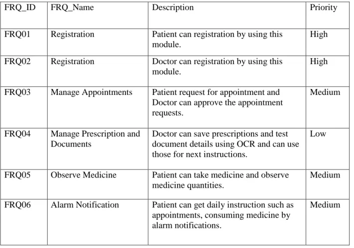
Requirement prioritization is used in software product management for determining which candidate requirements are high, medium and low of a software function module should be included in a certain release. Requirements are also prioritized to minimize risk during development so that the most important or high risk requirements are implemented first.
Table 2.1: Functional Requirements
FRQ_ID FRQ_Name Description Priority
FRQ01 Registration Patient can registration by using this module.
High FRQ02 Registration Doctor can registration by using this
module.
High
FRQ03 Manage Appointments Patient request for appointment and Doctor can approve the appointment requests.
Medium
FRQ04 Manage Prescription and Documents
Doctor can save prescriptions and test document details using OCR and can use those for next instructions.
Low
FRQ05 Observe Medicine Patient can take medicine and observe medicine quantities.
Medium
FRQ06 Alarm Notification Patient can get daily instruction such as appointments, consuming medicine by alarm notifications.
Medium
2.2.
Data RequirementsTable 2.2: Data Requirements
No Description Priority
DR01 Patient name, age, weight, contact, address. High
DR02 Doctor name, designation, specialty, address. High
DR03 Medicine name, quantity. High
DR04 Appointment date and time. High
2.3.
Performance Requirements 2.3.1. Speed and Latency RequirementsTable 2.3.1: Speed and Latency Requirements
No Description Priority
SLR01 When system requires the code for registration it should send verification code to entered number.
High SLR02 When patient send appointment request to the system, Firebase‟s database
should send info to server in real-time
High SLR03 When doctor accept appointment request, Firebase‟s database should add
info to server in real-time
High
2.3.2. Precision and Accuracy Requirements
Table 2.3.2: Precision and Accuracy Requirements
No Description Priority
SLR01 The input data should be accurate when Patient or Doctor provide data to the system.
High SLR02 All data should be in place accurately where it is associated Low
2.3.3. Capacity Requirements
Table 2.3.3: Capacity Requirements
No Description Priority
CR01 The mobile application size must able to load at hosting site. Medium CR02 The Firebase database size must be able to store the system data. Low CR03 System should support 100k user at the beginning version. Medium
CR04 System should support 1000 request per second. Medium
2.4.
Dependability Requirements 2.4.1. Reliability RequirementsTable 2.4.1: Reliability Requirements
No Description Priority
RR01 All confidential data must have to be encrypted. Medium RR02 All data should collect from users by permission and by accepting privacy
policy
Low RR03 No one can use user‟s data for any other purpose except system needs. Low
2.4.2. Availability Requirements
Table 2.4.2: Availability Requirements
No Description Priority
AR01 The system should work 24 hours a day. Medium
AR02 The system should provide the desired data to the user in time. Low
2.4.3. Robustness or Fault-Tolerance Requirement
Table 2.4.3: Robustness or Fault Tolerance Requirements
No Description Priority
FTR01 If the system has been crashed, it should not be more than an hour. Low
2.5.
Maintainability and Supportability Requirements 2.5.1. Maintenance RequirementsTable 2.5.1: Maintenance Requirements
No Description Priority
MR01 The system maintenance should be quick. Low
2.5.2. Supportability Requirements
Table 2.5.2: Supportability Requirements
No Description Priority
SR01 The system should support latest Android Version and Firebase version. Low
2.5.3. Adaptability Requirements
Table 2.5.3: Adaptability Requirements
No Description Priority
AR01 The system should adapt all upgrading version and time. Low AR02 New version of system should support latest Firebase modules. Low
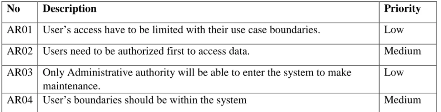
2.6.
Security Requirements 2.6.1. Access RequirementsTable 2.6.1: Access Requirements
No Description Priority
AR01 User‟s access have to be limited with their use case boundaries. Low AR02 Users need to be authorized first to access data. Medium AR03 Only Administrative authority will be able to enter the system to make
maintenance.
Low
AR04 User‟s boundaries should be within the system Medium
2.6.1. Integrity Requirements
Table 2.6.1: Integrity Requirements
No Description Priority
IR01 Only authorized user can update data with their respective accessibility and authorization.
Medium IR02 Only administrative authority can access and update or delete user‟s
information.
Medium
2.6.2. Privacy Requirements
Table 2.6.2: Privacy Requirements
No Description Priority
PR01 The user data should not contain any private issues. Medium
PR02 All the confidential data should be encrypted. Low
2.7.
Usability and Human-Interaction Requirements Table 2.7: Usability RequirementsNo Description Priority
UR01 Patient request for appointment and Doctor can approve the appointment requests.
Medium UR02 Doctor can save prescriptions and test document details using OCR and can use
those for next instructions.
Medium UR03 Patient can take medicine and observe medicine quantities. Medium UR04 Patient can get daily instruction such as appointments, consuming medicine by
alarm notifications.
Medium
2.8.
Look and field Requirements 2.8.1. Appearance RequirementsTable 2.8.1: Appearance Requirements
No Description Priority
AR01 The user interface must be attractive. High
AR02 The user interface must be user friendly. Medium
AR03 The user interface must be user interactive with user experiences. High
2.8.2. Style Requirements
Table 2.8.2: Style Requirements
No Description Priority
SR01 The interface color should be material. Low
Chapter 3
System Analysis
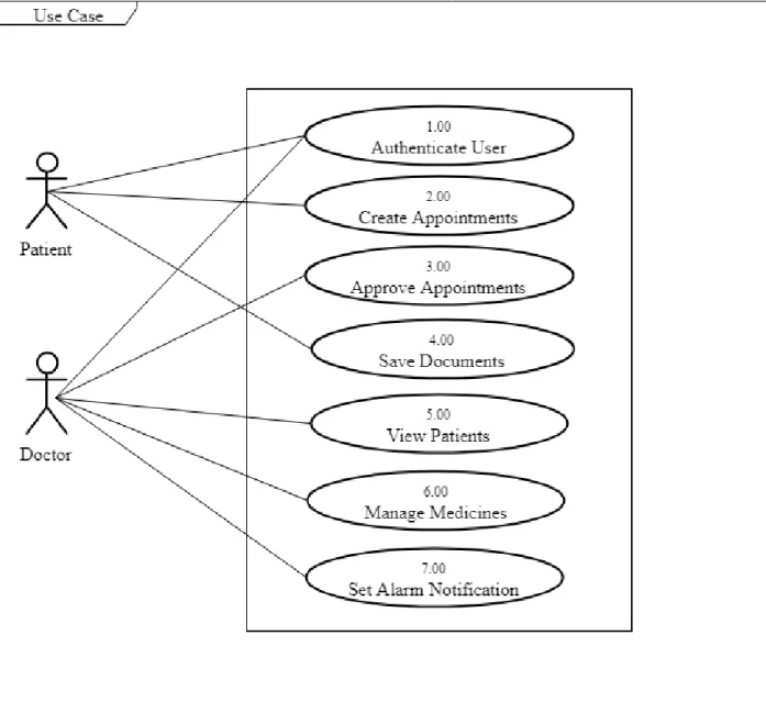
3.1. Use Case
A use case is a methodology used in system analysis to identify, clarify, and organize system requirements. In this context, the term "system" refers to something being developed or operated, such as a mail-order product sales and service website. Use case diagrams are employed in UML (Unified Modeling Language), a standard notation for the modeling of real-world objects and systems [4].
Figure 01: Use Case Diagram
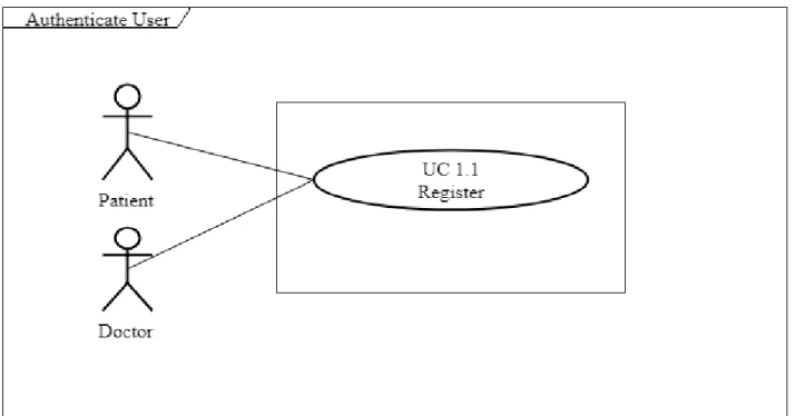
3.2. Use Case Description 3.2.1. Authenticate User
User authentication is a process that allows a device to verify the identity of someone who connects to a network resource. There are many technologies currently available to a network administrator to authenticate users [5].
Figure 02: Use Case: Authenticate User
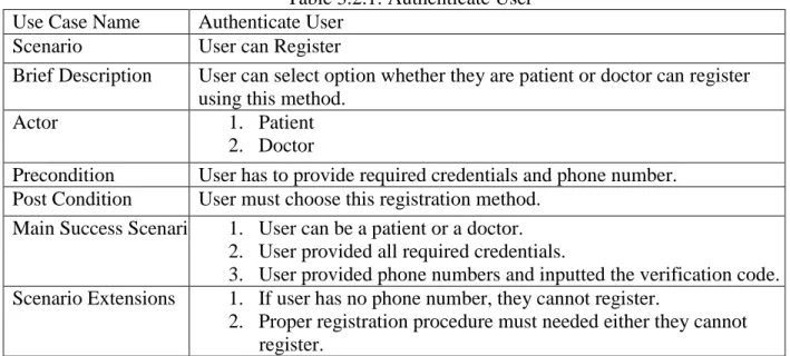
Table 3.2.1: Authenticate User Use Case Name Authenticate User
Scenario User can Register
Brief Description User can select option whether they are patient or doctor can register using this method.
Actor 1. Patient
2. Doctor
Precondition User has to provide required credentials and phone number.
Post Condition User must choose this registration method.
Main Success Scenario 1. User can be a patient or a doctor.
2. User provided all required credentials.
3. User provided phone numbers and inputted the verification code.
Scenario Extensions 1. If user has no phone number, they cannot register.
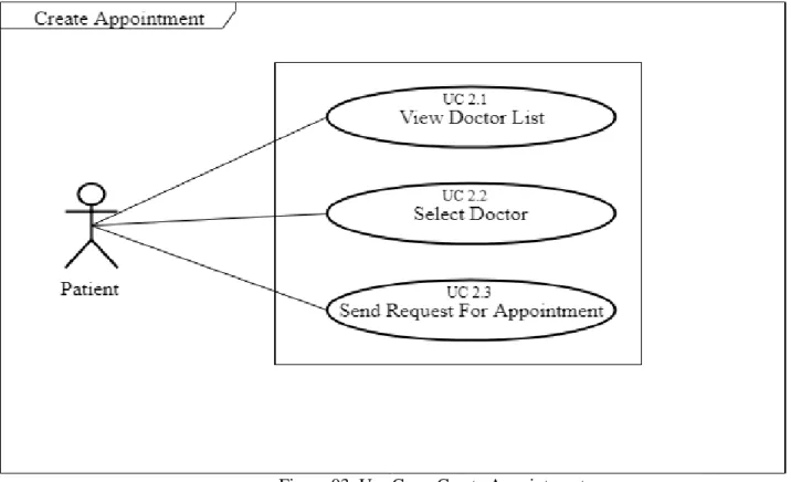
3.2.2. Create Appointment
Creating an appointment is a way to block out time for a consultancy between a Doctor and a Patient. An appointment is useful for an individual to block off time in his/her calendar for consultancy.
Figure 03: Use Case: Create Appointment
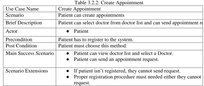
Table 3.2.2: Create Appointment Use Case Name Create Appointment
Scenario Patient can create appointments
Brief Description Patient can select doctor from doctor list and can send appointment request.
Actor ● Patient
Precondition Patient has to register to the system.
Post Condition Patient must choose this method.
Main Success Scenario ● Patient can view doctor list and select a Doctor.
● Patient can send an appointment request.
Scenario Extensions ● If patient isn‟t registered, they cannot send request.
● Proper registration procedure must needed either they cannot send a request.
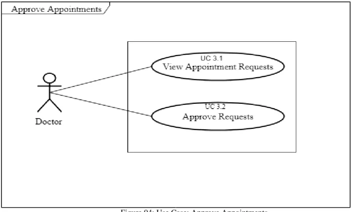
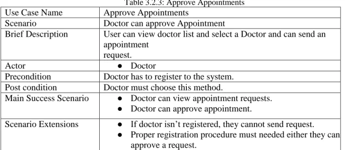
3.2.3. Approve Appointments
Approving an appointment is a way to block out time for a consultancy between a doctor and a patient. An appointment is useful for an individual to block off time in his/her calendar for consultancy.
Figure 04: Use Case: Approve Appointments
Table 3.2.3: Approve Appointments Use Case Name Approve Appointments
Scenario Doctor can approve Appointment
Brief Description User can view doctor list and select a Doctor and can send an appointment
request.
Actor ● Doctor
Precondition Doctor has to register to the system.
Post condition Doctor must choose this method.
Main Success Scenario ● Doctor can view appointment requests.
● Doctor can approve appointment.
Scenario Extensions ● If doctor isn‟t registered, they cannot send request.
3.2.4. Save documents
Using system, Doctor can save files to the documents function of the patient profile. The system will use OCR (Optical Character Recognition) for saving documents for printed hard copy or a png file for hand written documents. The program may use Firebase database or default phone‟s specific folder to save a file. Patient can save documents and Doctor can view those documents for future prescription.
Figure 05: Use Case: Save Documents
Table 3.2.4: Save Documents Use Case Name Save Documents
Scenario Doctor can save documents and also patient can view documents.
Brief Description Doctor can save documents, Doctor and Patient can view those documents for future prescription.
Actor ● Patient
● Doctor
Precondition Doctor has to save documents to the system.
Post condition Doctor must choose this method.
Main Success Scenario ● Doctor can save documents.
● Patient can view those documents.
Scenario Extensions ● If patient didn‟t save documents, doctor cannot view documents.
3.2.5. View Patients
Doctor can view all enrolled patients and can select patient.
Figure 06: Use Case: View Patients
Table 3.2.5: View Patients Use Case Name View Patients
Scenario Doctor can see enrolled patients.
Brief Description Doctor can see enrolled patients list.
Actor ● Doctor
Precondition Appointment request accepted.
Post condition Doctor must choose this method.
Main Success Scenario ● Doctor accepted the appointment request.
● Doctor can view enrolled patient list.
Scenario Extensions ● If doctor didn‟t accept appointment request, doctor cannot view patient list.
3.2.6.Manage Medicines
Doctor can input all prescribed medicines, taking time and quantity of the medicines. Doctor also can set daily alarm notification for consuming medicines. Patient can input the quantity of taken medicines.
Figure 07: Use Case: Manage Medicines
Table 3.2.6: Manage Medicines Use Case Name Manage Medicines
Scenario Patient can input medicine quantity. Doctor can input medicines, taking time and quantity.
Brief Description Patient can input medicine quantity. Doctor can input medicines, taking time and quantity. Doctor also can set daily alarm notification for consuming medicines
Actor ● Patient
● Doctor
Precondition Patients are enrolled.
Post condition Doctor must choose this method. Patient have to give medicine quantity.
Main Success Scenario● Doctor accepted the appointment request. Patients are enrolled.
● Patient gave medicine quantity.
Scenario Extensions ● If doctor didn‟t accept appointment request, doctor cannot view patient list.
3.2.7. Set Alarm Notifications
Doctor will set appointment time, input medicines and input medicine-taking times. Patient will input taken medicine quantity.
Figure 08: Use Case: Set Alarm Notification Table 3.2.7: Set Alarm Notification
Use Case Name Set Alarm Notification
Scenario Doctor will set appointment time, input medicines and medicine-taking times.
Patient will input taken medicine quantity
Brief Description Doctor will set appointment time, input medicines and input medicine-taking times. Patient will input taken medicine quantity
Actor ● Patient
● Doctor
Precondition Enrolled patients are prescribed.
3.3. Activity Diagram
3.3.1. Activity Diagram for Patient
Activity diagram is another important behavioral diagram in UML diagram to describe dynamic aspects of the system. Activity diagram is essentially an advanced version of flow chart that modeling the flow from one activity to another activity [6] [14].
Figure 09: Activity Diagram: Patient
3.3.2. Activity Diagram for Doctor
Chapter 4
System Design Specification
4.1. Sequence Diagram
UML Sequence Diagrams are interaction diagrams that detail how operations are carried out.
They capture the interaction between objects in the context of a collaboration. Sequence Diagrams are time focus and they show the order of the interaction visually by using the vertical axis of the diagram to represent time what messages are sent and when [7].
4.1.1. System Sequence Diagram: Authenticate User: Patient Patient can registration by requesting to the system.
Figure 11: System Sequence Diagram: Authenticate User: Patient
4.1.2. System Sequence Diagram: Authenticate User: Doctor Doctor can registration by requesting to the system.
Figure 12: System Sequence Diagram: Authenticate User: Doctor
4.1.3. System Sequence Diagram: Create Appointment Patient can see the doctors list and can send appointment requests.
Figure 13: System Sequence Diagram: Create Appointment
4.1.4. System Sequence Diagram: Approve Appointments Patient can send appointment request and doctor can approve requests.
4.1.5. System Sequence Diagram: View Patient List Doctor can view patient list.
Figure 15: System Sequence Diagram: View Patient List
4.1.6. System Sequence Diagram: Manage Medicine: Doctor Doctor can manage medicine name, time and quantity.
Figure 16: System Sequence Diagram: Manage Medicine: Doctor
4.1.7. System Sequence Diagram: Manage Medicine: Patient Patient can manage medicine quantity.
Figure 17: System Sequence Diagram: Manage Medicine: Patient
4.1.8. System Sequence Diagram: Manage Medicine Timer Doctor can manage medicine time.
4.1.9. System Sequence Diagram: Upload Documents Doctor can upload patient documents.
Figure 19: System Sequence Diagram: Upload Documents
4.1.10. System Sequence Diagram: View Documents Patient and doctor can view documents.
Figure 20: System Sequence Diagram: Upload Documents
4.1.11. Sequence Diagram: Patient Sequence diagram for patient.
Figure 21: Sequence Diagram: Patient
4.1.12. Sequence Diagram: Doctor Sequence diagram for doctor.
Figure 22: Sequence Diagram: Doctor
4.2. Data Flow Diagram 4.2.1. DFD Level 0
A data flow diagram (DFD) illustrates how data is processed by a system in terms of inputs and outputs. As its name indicates its focus is on the flow of information, where data comes from, where it goes and how it gets stored [8].
Figure 23: Data Flow Diagram: Level 0
4.2.2. DFD Level 1
The Level 1 DFD shows how the system is divided into sub-systems (processes), each of which deals with one or more of the data flows to or from an external agent, and which together provide all of the functionality of the system as a whole [9].
Figure 24: Data Flow Diagram: Level 1
4.2.3. Entity Relationship Diagram
An entity relationship diagram (ERD), also known as an entity relationship model, is a graphical representation of an information system that depicts the relationships among people, objects, places, concepts or events within that system. An ERD is a data modeling technique that can help define business processes and be used as the foundation for a relational database [10].
Rectangle: Uses to define entity
Eclipse: Uses to attribute
Diamond: Uses to define action
Figure 25: Entity Relationship Diagram
4.2.4. Class Diagram
A class diagram in the Unified Modeling Language (UML) is a type of static structure diagram that describes the structure of a system by showing the system's classes, their attributes, operations (or methods), and the relationships among objects [11].
Figure 26: Class Diagram
Chapter 5
User Interface
5.1. User Interface 5.1.1. Patient Profile
5.1.2. All Doctors List
5.1.3. Doctor‟s Profile
5.1.4. Appointment Requests and Approve Procedures
5.1.5. Input Medicines
5.1.6. Medicines Consuming Times
5.1.7. Input Suggestions
Chapter 6
Development Tools and Technologies
6.1. User Interface Technologies
● Android XML SDK version 26.1.1
● UTF-18
● SystemUI.apk
● Framework-res.apk
● Framework.jar
● Material Font
● Material icon
6.2. Implementation Technologies 6.2.1. Java SE 11 (18.9 LTS)
A concurrent, class-based, object-oriented programming language. JDK 11 the version is currently open for bug fixes.
6.2.2. Android.Content.Pm.PackageManager
A deprecated package in API level 24. It is a mocking framework like Mockito [15].
6.2.3. Android 8.1 Framework
Android 8.1 (API level 27) introduces a variety of new features and capabilities for users and developers. Improved memory usage across the platform to ensure that apps can run efficiently on devices with 1GB or less RAM. New hardware feature constants to let you target the distribution of your apps to normal or low-RAM devices through Google Play.
6.2.4. Firebase
Firebase is a mobile and web application development platform developed by Google. Firebase provides a real-time database and backend as a service. The service provides application developers an API that allows application data to be synchronized across clients and stored on Firebase's cloud.
6.2.5. Google Cloud Vision API
Cloud Vision API provides a comprehensive set of capabilities including object detection, ocr, explicit content, face, logo, and landmark detection.
6.3. Platform and Environment 6.3.1. Hardware
● Processor: Intel Core i5.
6.3.3. Version Control
● Github
https://github.com/Mehedi847/medicare_plus
Chapter 7
System Testing
7.1. System Testing
Software testing is a process, to evaluate the functionality of a software application with an intent to find whether the developed software met the specified requirements or not and to identify the defects to ensure that the product is defect free in order to produce the quality product [12] [16].
7.2. System Testing
The importance of the test plan is to show how the system is to be tested and gives precise procedure to be followed during test plan. The test data is identified, what is being tested and the expected outcome as well as actual input. Test plan is one of the standard documents that should be produced in most software engineering projects. If the project does not have any test plan this means that, the system produced is low quality. This may not be acceptable to the user it will not satisfy their needs. The test plan should be written as soon as requirements have been identified.
The system will be tested with sample data to see how it would handle input and output functions as well as extreme data or conditions to determine the system behavior in overloaded situation, which will directly slow the system that behaves in failure, or extreme situation.
7.3. System module need to be tested
Registration
Manage Appointments
Manage Prescription and Documents
Observe Medicine
Alarm Notification 7.4. Test Case
A test case is a set of conditions or variables under which a tester will determine whether a system under test satisfies requirements or works correctly. The process of developing test cases can also help find problems in the requirements or design of an application [13].
● Ensure that logical decisions on their true and false side.
● Practice all the logical decisions on their true and false side.
● Check equivalent partitions and boundary value within their operations bounds.
● Exercise internal data structure to assure their validity.
7.4.1. Test Case of Registration
Test Case: TC01 Test Case Name: Testing the registration panel.
System: Medicare Plus Requirements ID: FRQ_01 ( Registration) Designed by: Saiful Islam Design Date: 28.11.18
Executed by: Mehedi Hasan Shakil Execution Date: 28.11.18
Short Description: This field will handle the registration functionality of the system.
Precondition: Open the application.
Table 7.4.1: Test Case of Registration
Steps Action Input Actual
Result
Expected System Response Pass/Fail
01 Enter all info in required field and a valid phone number.
Name, weight, age, address
Get registered.
Registered in into the system. Pass
02 Valid info and invalid phone number.
Contact number
Not
registered in and an error toast
message.
Not registered in and an error toast message.
Pass
03 Click confirm without any inputted data.
Click confirm
Show “Input field
required”
toast message.
Showed “Input field required” toast message.
Pass
7.4.2. Test Case of Manage Appointments
Test Case: TC02 Test Case Name: Manage Appointment.
System: Medicare Plus Requirements ID:FRQ_03 (Manage Appointments) Designed by: Mehedi Hasan Shakil Design Date: 30.11.18
Executed by: Saiful Islam Execution Date: 30.11.18
Short Description: This field will handle the appointment functionality of the system.
Precondition: Registered the application.
Table 7.4.2: Test Case of Manage Appointments
Steps Action Input Action Result Expected System Response
Pass/Fail
01 Select doctor from doctor list and send a request.
Select doctor list
Doctor selected and send
appointment request.
Send an appointment request.
Pass
02 Approve appointment.
Click approve Not added in enrolled list.
Added in enrolled list. Fail
03 Approve appointment.
Click approve Added in enrolled list.
Added in enrolled list. Pass
7.4.3. Test Case of Observe Medicine
Test Case: TC03 Test Case Name: Manage Medicine
System: Medicare Plus Requirements ID: FRQ_05 ( Observe Medicine) Designed by: Saiful Islam, Mehedi Hasan
Shakil
Design Date: 04.11.18
Executed by: Saiful Islam, Mehedi Hasan Execution Date: 04.11.18
Table 7.4.3: Test Case of Observe Medicine
Steps Action Input Action
Result
Expected System Response
Pass/Fail
01 Input medicine name, time and quantity to the module.
Medicine name, time and quantity
Successfully inputted into the system.
Successfully inputted into the system.
Pass
02 Input medicine name, taking time and quantity to the module.
Medicine name, time and quantity
Successfully inputted into the system.
Successfully inputted into the system.
Pass
03 Input taken medicine quantity and time.
Medicine quantity
Didn‟t input successfully.
Inputted successfully. Fail
04 Input taken medicine quantity and time.
Medicine quantity
Inputted successfully.
Inputted successfully. Pass
7.5. Features not yet tested
Table 7.5: Features not yet tested
No Name User
1 Get documents by OCR using phone‟s camera.
Patient
2 Show documents. Patient/Doctor
3 Alarm Notification Patient/Doctor
Chapter 8
Project Summary
8.1. GitHub Link
https://github.com/saifjewel/medicarePlus
8.2. Limitations
● The system has only few functionalities for international perspective.
● Sometimes the system needs high speed mobile internet.
8.3. Obstacle & Achievements Obstacle:
● Learning new technology and environment
● Limited time and budget Achievements:
● Learnt new technology
● Successfully built a project for production level
8.4. Conclusion
In our society within every three months, we have to deal appointments with consultants for various kind of diseases. After every appointment, we have many important papers or documents and sometimes we have been lost those or those gone messy. Again, we need to take medicine before or after meal at different times, but we often forget, exact which medicine should take, and we get confused. That misunderstanding seems not to be taken medicine as well. Again, sometimes medicines are finished but we cannot notice. Then there are many problems have been faced. Sometimes these problems also create difficulties for consultants and affect their regular consultancy. The system will offer help to decrease those problems and make our daily life easier.
8.5. Future Work
Though the system was developed as fine but the future work will include some major changes, as-
● Payment gateway will be integrated
● Real time communication media like chat
● Notification will be introduced.
● Web Platform
References
[1] Proposed system model
https://www.quora.com/What%E2%80%99s-meant-by-a-proposed-system-in-projects [Accessed: 02 December 2018]
[2] Gantt chart
https://searchsoftwarequality.techtarget.com/definition/Gantt-chart [Accessed: 02 December 2018]
[3] SRS
https://searchsoftwarequality.techtarget.com/definition/software-requirements- specification [Appointment: 10July 2018 to 01 December 2018]
[4] Use case diagram
https://whatis.techtarget.com/definition/use-case-diagram [Accessed: 02 December 2018]
[5] User authentication
https://www.watchguard.com/training/fireware/82/authent2.htm [Accessed: 02 December 2018]
[6] Activity diagram
https://www.visual-paradigm.com/guide/uml-unified-modeling-language/what-is- activity-diagram/ [Accessed: 02 December 2018]
[7] Sequence diagram
https://www.visual-paradigm.com/guide/uml-unified-modeling-language/what-is- sequence-diagram/ [Accessed: 02 December 2018]
[8] Data flow diagram
https://www.smartdraw.com/data-flow-diagram/ [Accessed: 02 December 2018]
[9] Data flow diagram level 1
https://en.wikipedia.org/wiki/Data_flow_diagram [Accessed: 02 December 2018]
[10] ERD diagram
https://searchdatamanagement.techtarget.com/definition/entity-relationship-diagram-
ERD [Accessed: 02 December 2018]
[11] Class diagram
https://www.visual-paradigm.com/guide/uml-unified-modeling-language/what-is- class-diagram/ [Accessed: 02 December 2018]
[12] Software system
https://www.softwaretestingmaterial.com/software-testing/ [Accessed: 02 December 2018]
[13] Test case
http://softwaretestingfundamentals.com/test-case/ [Accessed: 08 October 2018]
[14]. Module Diagram:
https://www.draw.io [Accessed: 08 October 2018]
[15]. Android Package Manager
https://dzone.com/articles/depth-android-package-manager [Accessed: 28 October 2018]
[16]. Software System Testing:
http://softwaretestingfundamentals.com/system-testing [Accessed: 02 December 2018]