This is to certify that this project and thesis entitled "DESTRUCTION OF SUBSTATION 132/33 KV" was done by the following students under my direct supervision and this work was done by them in the laboratories of the Department of Electrical and Electronic Engineering. under the Faculty of Engineering of Daffodil International University in partial fulfillment of the requirements for the degree of Bachelor of Science in Electrical and Electronics Engineering. Mahfuzul Hasan Session ID: Fall 2016 has been accepted as satisfactory in partial fulfillment of the requirements for the degree of Bachelor of Science in Electrical and Electronics Engineering on January 1, 2020.
LIST OF TABLES
List of Abbreviations
List of Symbols
ACKNOWLEDGEMENT
ABSTRACT
INTRODUCTION
- Introduction
- Company Profile
- Objective
- Methodology
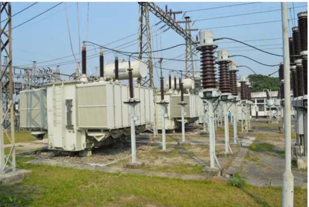
Before doing this place, we tend to have purely theoretical data on these subjects, but by the completion of associate place in Kallyanpur, we have also obtained sensible data. This report is focused on 132/33 KV substation at Kallyanpur near around Shymoli, Dhaka North City, Dhaka. Primary information: knowledge is gathered by personal observation and dealing with the substation engineers at Kallyanpur substation.
Secondary information: company website and various single line diagrams provided by the engineers that we usually work with.
SUB-STATION
- Introduction
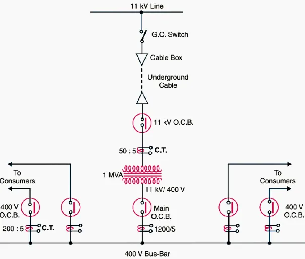
- Single Line Diagram of a sub-station
- Classification Of sub-station
- According To Service Requirement
- According To Constructional Features
- Component of Substation
- Selection of Site
- Present Power Generation
- Difference between Outdoor and Indoor Substation
Here we discuss two main ways of classifying substations, according to service requirements and construction characteristics. A substation may be asked to change voltage level or improve factor or convert air conditioning power to DC control and so on. The site chosen should be as close to the hope focus as can reasonably be expected.
The location of the substation should be as close to the city as possible, but should not have open cities, airports and military/police facilities. The land should have an adequate floor plan zone to accommodate substation equipment, structures, staff quarters, material storage areas such as storage yards and warehouses and so on with streets and room for future development.
Component of Substation
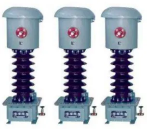
- Instrument Transformer
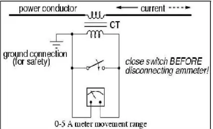
- Current Transformer
- Voltage Transformer
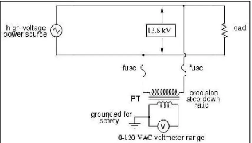
- Potential Transformer
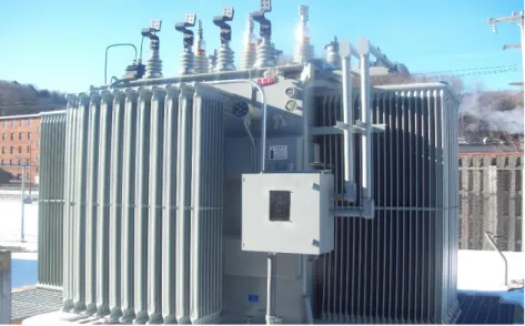
- Power Transformer
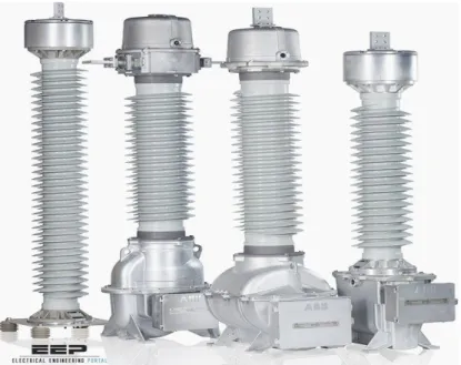
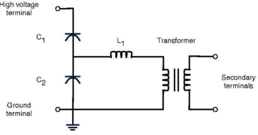
- Capacitor Voltage Transformer
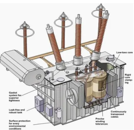
- Main Parts of a Transformer
- Difference between Current and Potential Transformer
- Insulator
- Conductor
- Isolator
- Circuit Breaker
- Comparison of Circuit Breaker and Isolator
- Bus Bar
- Lightening Arresters
- Earthling
- Capacitor Banks
- Wave Trapper
- Automatic Circuit Recloser
- Oil Circuit Recloser
- Relay
A power transformer can reasonably be a transformer accustomed to transfer power to any part of an electrical or electronic circuit between the generator and thus the dispersion of the primary circuits. As mentioned earlier, the main purpose of the associated level isolator is safety, because if a fault occurs in one section of the circuit or power supply, the electrical isolator is used as a switch that isolates that section from various sections of the system until repairs are made. In similar situations, isolators additionally ensure the safety of employees during regular maintenance and repair of system capabilities.
The electrical switch is used to break the circuit if a fault occurs in any of the instruments. An electrical busbar is defined as a conductor or a group of conductors used to assemble power from incoming feeders and distribute it to outgoing feeders. In case of propagation of a fault, the electric fuse is switched off and therefore the damaged part of the bus is finally disconnected from the circuit.
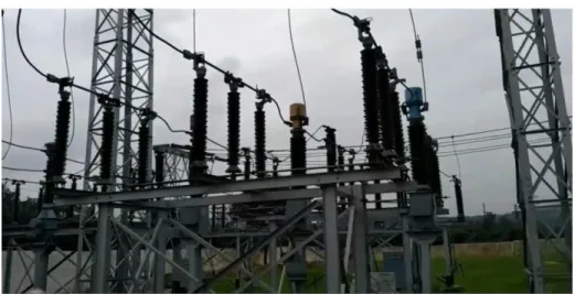
The lightning rod is grounded to the earth for the purpose of destroying lightning to the ground. These are located at the passage from the transmission line to the substation and as close as possible to the transformer terminals. A lightning arrester or flood arrester is a defensive gadget that directs the power voltage on the power frame to the ground.
One end of the inverter is associated with the terminal of the hardware to be secured and the opposite end is adequately grounded. The length of the hole is set so that ordinary stress is not sufficient to cause a bend, but a dangerously high stress will separate the air protection and structure a circular segment. The characteristic of the non-direct opposition is that its obstruction increments as the voltage (or current) increments and vice versa.
The earth conductor of the tangle can be covered under the earth to a careful depth of the entanglement of the tangle 0.5 meters. The wave trap is one of the substation components placed on the incoming lines for catching high frequency waves. Besides that due to maintenance of the substation to isolate the line first it can be isolated by the line where the arc is properly extinguished.
Transmission of Substation
- Introduction
- Overhead transmission
- Classification
- Overhead power transmission lines components
- Types of OHTL Supports
- Self-supporting; which might be of the following types (examples are shown in figure 5)
- Guyed or non-self-supported: although those types of supports were introduced at the second quarter of the 20th century, but their use declined with time for the transmission
- Suspension supports: used for sections were the line is running straight with some allowed deviation usually not to exceed 10 degrees
- Terminal supports: usually used at substation entry as they are designed to take full mechanical tension on one side and no tension (or slack) on the other side
- General considerations for OHTL supports design
- The line electrical requirements such as
- The line minimum mechanical strengths requirements and required safety factors
- Environmental & and climatic conditions including the proposed preliminary routes/
- Wind Loads: this step includes the determination of wind loads affecting both, the support and conductors
- Conductors load: this step includes the calculation of mechanical loads resulting from conductor’s tensions (the maximum working tension and Every day stress), short Circuit
- Induced vibration effects
- Finalize the design based on combined Loads: this is necessary to achieve a reasonable design that matches the requirements without being oversized and achieved by the
- Applying the safety factor
- Design verification through prototyping and type testing of the supports
- What is Underground Electric Transmission?
The invention of the Strain Isolator was a critical factor in allowing higher voltages to be used. In the late 19th century, the limited electrical strength of Telegraph-style Pin insulators limited the voltage to no more than 69,000 Volts. The main function of the OHTL supports (also called: towers, structures or pylons) is to provide the necessary mechanical support for the transmission conductor at the design electrical clearance from ground and also from other phase conductors.
Another use of guided supports is for the rapid restoration of the transmission system in the event of the collapse of the transmission supports or for the diversion of transmission circuits during projects or modification works and for this purpose, some specially designed supports called Systems of Emergency Recovery (ERS) that can be mounted on short-term use in various configurations. Additionally, OHTL supports can be classified based on the number of circuits they carry (supports); and thus, it can be single circuit support, dual circuit support or quad circuit support and in some rare cases, the OHTL support is designed to carry one or more transmission circuits on top of the support and a circuit / distribution circuits or insulated fiber communication cables in the lower part, but the use of this type of supports will only be possible with OHTL with short spaces between supports. In this section, the basic steps for the design of airline supports are briefly defined, remembering that in the design process, and although it is to some extent a standardized process, the design is greatly influenced by the data and requirements provided by the service. themselves which should be as accurate as possible to reflect the local working conditions of the line that the project has to meet.
The minimum required distance in the middle of the span of the lowest conductor above ground level or to other conductors at the intersection with the conductors of other conductors. The minimum required insulator age path and thus the minimum length of the insulator assembly. During the design of the support, it should always be considered that the design of the design meets the load requirements within the economic requirements of the utility.
Finalize the design based on the combined loads: this is necessary to achieve a reasonable design that meets the requirements without oversizing and achieved by the design that meets the requirements without oversizing and achieved by assuming that not all of the above factors will be in higher together. If an electrical fault ruptures the underground pipe and generates a dielectric fluid in the nearby mud, then liquid nitrogen trucks are assembled to repair the damaged part of the pipe location. Pipe and soil statistics are frequently monitored throughout the repair period.
Underground power transmission cable makes better use of land without the sight of cables and poles, leading to improved property values.
Distribution of Substation
- Distribution Transformer
- Uses of distribution transformer
- Main Element of Overhead Line
- Conductor
- Pole
- Types of Pole
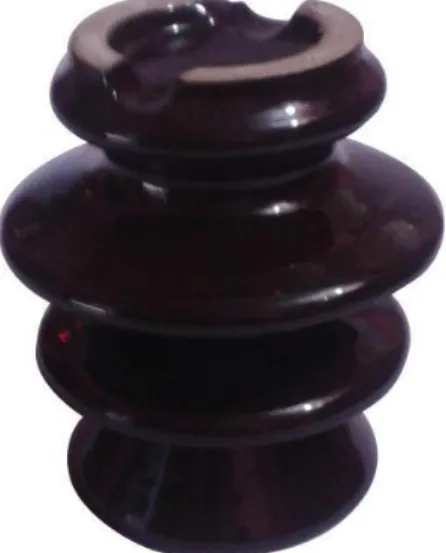
- Insulators
- Types of Insulator
- Instrument Transformer
- Feeder
The supporting structures for overhead line conductors are various types of shafts and towers called line supports. The line supports used for the transmission and distribution of the electric power are of various types, that is. The overhead line conductors must be supported on the poles or tower in such a way that current from conductors does not flow to earth through supports as line conductors must be properly insulated from supports.
The insulator must be non-porous, free of dirt and cracks, otherwise permeability will decrease. For high voltage activity, the low variation meter is used with a series connected high resistance. For these functions specially designed precision size connection instrument transformers are used in connection with ordinary A.C instruments of low variation.
In power building, a feeder line is a piece of an electrical circulation arrange, usually a spiral circuit with the center of the road voltage.
Protection of Substation
- Transformer Protection
- Feeder Protection
- Lightening Arrester Protection
- Fire Protection
- Earth Screen
- Surge Absorbent
- Neutral Grounding Resistance (NGR)
A surge protector may be a device used in an electrical power system to protect the system's insulation and conductors from the harmful effects of lighting. The fire protection device must be intact within the store yard for the protection of the kit items throughout storage. The power plant and therefore the substation usually have a lot of expensive instruments.
It consists of a network of copper conductors mounted throughout the substation or power plant. The screen is correctly connected to the planet at at least 2 points via an incidental resistance. With the prevalence of the direct hit at the station, the screen provides a coffee resistance path by connecting the light shot to the bottom.
Flood-retentive can be a hedging gadget that lessens the sharpness of the wavefront of a flood by entraining flood vitality. Although every flood diverter and flood preserver removes the flood, the style under which it is done is very surprising inside the 2 gadgets. The flood diverter redirects the flood to the ground, yet the flood receiver consumes the vitality of the flood.
The non-partisan establishment of obstruction is used to limit the planet's current shortage throughout the release state below the express value. Unbiased obstruction setup is used in 11KV generating station to limit internal current as much as possible.
CONCLUSION AND RECOMMENDATION
Conclusion
Recommendation