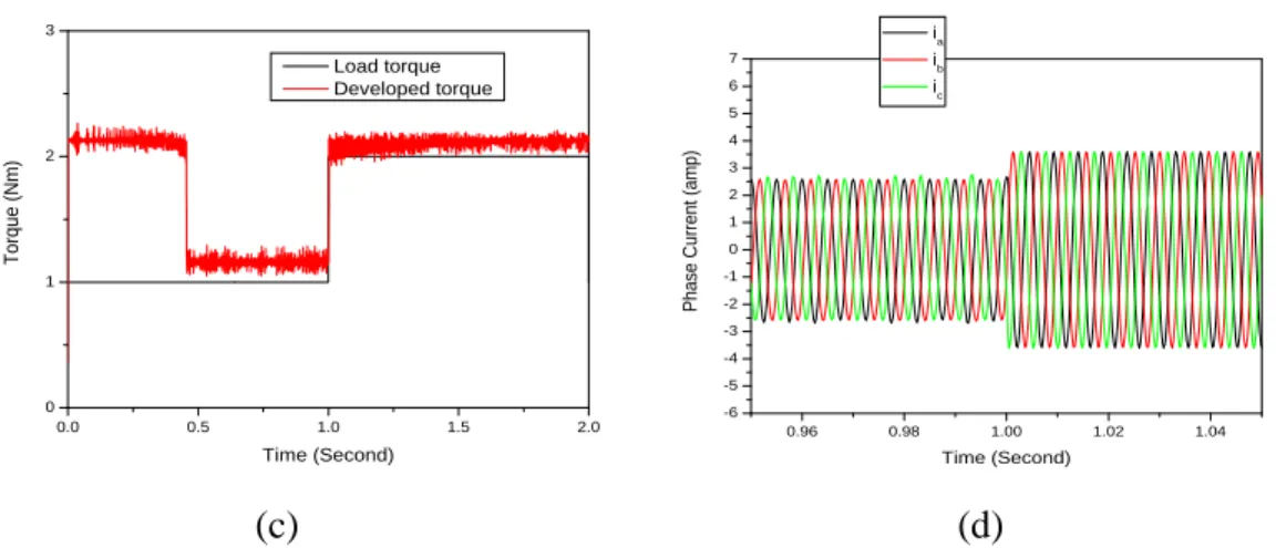
5.4 (a) Rated rotor angle, (b) Speed, (c) Developed electromagnetic torque45 and (d) Three-phase currents for the proposed IPMSM. 5.5 (a) Rated rotor angle, (b) Speed, (c) Developed electromagnetic torque 46, and (d) Three-phase currents for the proposed IPMSM drive.
Introduction
Motivation
This algorithm used the stator voltages and currents measured from the IPMSM drive to obtain the estimated speed. The main objective of this project work is to investigate the performance of IPMSM drive with 4S3P inverter without position sensor.
Previous Work
Equations of the IPMSM are derived in the rotor reference frame and the equivalent circuit is presented without dampers. It was implemented based on the output of the synchronous reference voltage from the PI current controller to the PWM inverter.
Outline of the Present Work
In the above works, none of them have considered a real simulation of the drive system in Simulink operating in constant torque and flux weakening regions.
Introduction
Interior Permanent Magnet Synchronous Motor Drive System
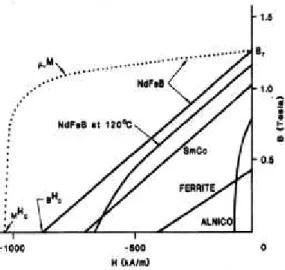
Interior Permanent Magnet Materials
- Direction of field flux
- Flux density distribution
- Interior Permanent Magnet radial field motors
Depending on the placement they are either called as surface permanent magnet motor or inside permanent magnet motor. The permeability of the permanent magnet is almost that of air, so the magnetic material becomes an extension of the air gap.
Conclusion
They do not have the slip losses that occur when the rotor rotates at a slightly slower speed than the stator, because the process of electromagnetic induction requires a relative motion called "slip" between the rotor conductors and the stator rotating field, which is specific to IM. operation. The slip makes the IM asynchronous, which means that the rotor speed is no longer exactly proportional to the supply frequency [22].
Introduction
Mathematical Model of IPMSM
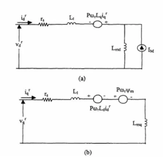
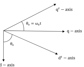
Now the quantities in the d-q stationary frame can be converted to the d − q synchronous rotating frame with the help of Fig. Kuv andv are the d and q axis voltages i and i are the d and q axis currents, ψ and ψ are the d and q axis flux linkages, respectively, r is the stator resistance per phase and ω is the stator frequency. L and L are the d- and q-axis inductances, L and L are the d- and q-axis magnetizing inductances, and L is the leakage inductance per phase.
According to equation (3.23), a permanent magnet synchronous motor can be represented by the d-axis and q-axis equivalent circuit diagrams as shown in the figure. The torque developed by the machine can be obtained by considering the power input to the two sources as shown in the figure. Where T is the load torque (in Nm), B is the friction damping coefficient (in Nm/rad./s) and J is the inertia constant of the rotor (in kg-m.
Vector Control Strategy for IPMSM Drive
In the case of the surface-mounted permanent magnet synchronous motor, L ≅ L, so the contribution of the second term in Equation (3.26) is negligible. Therefore, the torque equation of the surface-mounted permanent magnet synchronous motor becomes linear and thus the control task is easier. However, in the case of the internal permanent magnet synchronous motor (IPMSM), L is greater than L.
Thus, the complexity of the IPMSM machine control arises due to the nonlinear nature of the torque equation (3.26). It should be noted that the torque expressions of equations (3.31) and (3.32) are identical and decoupled. In the case of the IPM motor, the d-axis current is negative and demagnetizes the main flux provided by the permanent magnets.
Parks Transformation and Dynamic d-q Modeling
IPM Motor Control
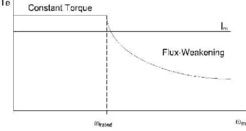
The limit is set by the rated speed of the motor, at which speed the constant torque operation ends and the flux decay begins as shown in figure 3.5.
Field Oriented Control of IPM Motors
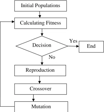
Genetic Algorithm (GA)
Where x and x are the old chromosomes, α is the random value from 0 to 1, x and x are the new chromosomes. It is a process of providing an occasional random change of the value at a particular string position. In the project, Time Variant Mutation (TVM) operator is used to mutate all variables of offspring [32].
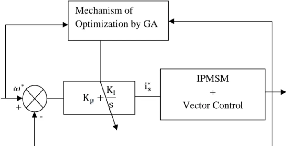
Care should be taken that this type of mutation may initially violate the domain of object variables. In this project work, Genetic Algorithm is used to optimize the gains of the PI controller in the speed loop of the control system to compare with the performance of the PI based control system.
Comparative analysis between GA and PI based Synchronous Motor Drive
Mathematical Model of 4S3P Inverter
The phase voltage equations of the motor can be written as a function of the switching logic of the switches and the DC switching voltage [33] by. Where,V,V,V are inverter output voltages: V is voltage across the DC switching capacitors; S,S is switching function for each phase leg.
Controller Models
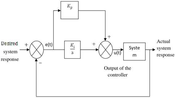
PI Controller
This accumulated error signal is multiplied by a gain factor I and becomes the output term I of the PI controller. For a controller with proportional control action, the controller output value u(t) is proportional to the actuating error signal e(t). For an action integral controller, the controller output value u(t) changes at a rate proportional to the actuating error signal e(t).
Hysteresis current controller
Operation Principle of Hysteresis Modulation
Typical Hysteresis Current Controller
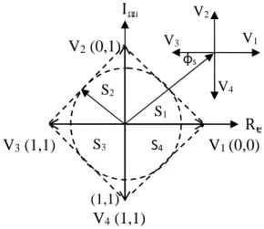
The space vector modulation technique differs from hysteresis modulation in that separate comparators are not used for each of the three phases. Instead, the reference voltage space vector Vs is produced as a whole, sampled at a fixed frequency, and then constructed by appropriately timing adjacent non-zero converter space vectors V1 to V6 and zero space vectors V0, V7. In this diagram, the conduction state of the three legs of the converter is represented by three logic variables, SA, SB, and SC.
A logic 1 means the top switch is conducting and a logic 0 means the bottom switch is conducting.
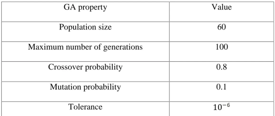
Tuning of the PI Speed Controller Using the Genetic Algorithm Approach
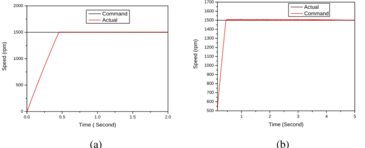
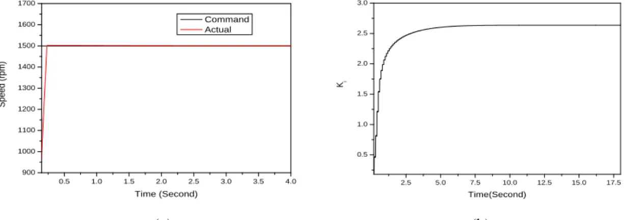
After giving the above parameters to the GA, the PI controller can be easily tuned and thus the performance of the system can be improved. The parameters of the PI speed controller obtained according to the optimization procedure with the GA technique are given below in Table 3.3. Applying GA, at t= 0.23 sec, the motor reaches the command speed shown in Fig.
Some fluctuations in electromagnetic torque are noted, which are due to switching of the units. About half the time of natural algorithm, the GA's speed response curve reaches the command speed.
Advantages of using GA based PI
Conclusion
Introduction
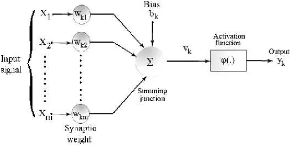
Models of a Neuron
Unlike a synapse in the brain, the synaptic weight of an artificial neuron can lie in a range that includes negative as well as positive values. An adder to sum the input signals, weighted by the neuron's respective synapses; the operations described here constitute a linear combinator. The enable function is also referred to as a squashing function in that it squashes (limits) the allowable amplitude range of the output signal to some finite value.
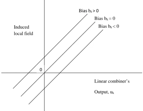
The use of bias bk has the effect of applying an affine transformation to the output uk of the linear combiner in the model of Figure 3.1, as shown by:. In particular, depending on whether the bias bk is positive or negative, the relationship between the induced local field or activation potential vk of neuron k and the linear combiner output uk is modified in the way that will be illustrated later; hereafter the term. In this figure, the effect of the bias is accounted for by doing any two points of view:.
Learning in Neural Networks
Real Time Recurrent Learning Algorithm
Real Time Recurrent Neural Network (RTRNN)
The RNN weights are dependent on the sampling frequency of the control system: this means that a retraining of the RNN is required if the sampling frequency varies.
Proposed IPMSM Control Scheme
- Adjusting the PI Gains
- Flux Program
- Coordinate Transforms .1 Vector Rotator
- Clarke Transform
- Hysteresis current controller Techniques
- Ramp Comparator Controller
- Improved Ramp Comparator Controller
The stationary axes a-, b-c- their two phase equivalents α-, β- and the rotating axes of the IPMSM are shown in fig. In the case of the hysteresis regulator, the switching frequency varies over the fundamental period. In the case of the fixed-band controller, the maximum switching frequency of the inverter is reduced, but the harmonic current is increased.
A mixed-band hysteresis regulator is used to achieve a compromise between the maximum switching frequency of the converter and the harmonic content of the current. Due to the fixed frequency of the triangular wave, the switching frequency of the inverter remains fixed. To overcome the aforementioned problems of the conventional ramp controller, an improved ramp comparator controller is used.
Conclusion
Where, i is the actual current of phase 'a', i∗ is the command current, i = i∗+H, is the upper band, i = i∗- H, is the lower band and H is the hysteresis band. A typical three-phase conventional ramp comparator controller is also shown in Fig.4.10 with the SW switch 'on' and bypassing the phase shifter. In the ramp comparator controller, the error signals between the actual motor currents and the corresponding command currents are compared with a high-frequency triangular waveform of fixed frequency and amplitude.
To avoid the multiple crossings of error signals with a triangular waveform, a hysteresis band is added to the controller. However, the disadvantages of this controller are that the actual motor current has some amplitude and phase errors, which become acute at high speed. In this controller, the current error signals are compared with three 120° phase-shifted triangular waveforms with the same fixed frequency and amplitude.
Introduction
RNN based Stator Flux and Rotor Position Estimation
Starting Performance of the IPMSM Drive
Performance under Different Operating Conditions
- Sudden Change of Load Torque
- Variation of Stator Parameters
- Speed Reversal
- Ramp Speed Change
- Sudden Disturbance Torque
- Presence of Computational Errors
The estimated rotor angle and the speed responses for changing load torque are shown in Fig. Sudden change of load torque does not affect the position estimation and causes a negligible oscillation in speed. A sudden load perturbation (1.5 N.m) for a very short duration of 0.1 second was applied to the IPMSM actuator.
Simulation studies show that the proposed control scheme is still able to accurately estimate the rotor angle. A sudden load disturbance was applied to the IPMSM drive for a very short duration of 0.1 second. Depending on the performance, it can be claimed that the performance of the proposed control scheme is insensitive to calculation errors within the range of -8% to 8%.
Conclusion
Conclusion
Based on the results of the previous chapters and the above discussion, it can be concluded that the proposed control scheme provides high performance control for synchronous motor drives.
Proposed for Future Research
Neumann, "Interior Permanent-Magnet Synchronous Motors for Adjustable Speed Drives," Industrial Applications, IEEE Transactions on, vol. Hirasa, "Loss Minimization Control of Permanent-Magnet Synchronous Motor Drives," Industrial Electronics, IEEE Transactions on, vol. Schmidt, "Modelling and Analysis of Permanent Magnet Synchronous Motor Considering Saturation and Core Loss," 1997.
Seung-Ki, "Speed control of internal permanent magnet synchronous motor drive for the flux attenuation," Industry Applications, IEEE Transactions on, vol. Margaris, "Loss minimization in vector-controlled internal permanent-magnet synchronous motor drives," Industrial Electronics, IEEE Transactions on, vol. Aydin, “Axial flux-mounted permanent magnet disk motors for smooth torque drive application,” in Electrical and Computer Engineering, vol.