Development of Sonar Sensor System for
Autonomous Underwater Vehicles Application
M.Shahrieel M.Aras
1, Nurul Syahirah Khalid
2, Hendra Hairi
3, Hyreil Anuar Kasdirin
41Faculty of Electrical Engineering,Universiti Teknikal Malaysia Melaka, Email : [email protected] 2
Faculty of Electrical Engineering,Universiti Teknikal Malaysia Melaka, Email: [email protected] 3 Faculty of Electrical Engineering,Universiti Teknikal Malaysia Melaka, Email: [email protected] 4 Faculty of Electrical Engineering,Universiti Teknikal Malaysia Melaka, Email: [email protected]
Abstract - This project is about the development of sonar
sensor system in purpose for Autonomous Underwater Vehicles (AUV) application. The concept of this project is using the ultrasonic sensor as a main device to transmit and receive the signal from the obstacle. The ultrasonic sensor will be combined to the ultrasonic circuit. Usually, the ultrasonic sensor is often used in robots for obstacle avoidance, map building and especially in navigation. Ultrasonic range sensor is works by emitting a short burst of 40 kHz sound. In addition, a small amount of sound energy is reflected by objects in front the device and returned to the detector or the receiver. The receiver sends this reflected signal known as echoes to the microcontroller to determine how far away the objects. However, to know how far away the objects it is using the speed of sound and time it took for the signal to be reflected. Unfortunately, echoes are not completely a product of distance. Different the medium will give the different speed and different result. It uses a Proowave Ultrasonic TXR and MikroC software as a compiler.
Keyword- Ultrasonic sensor; Sonar sensor, Echoes
I. INTRODUCTION
A sonar sensor is actually a device that used to transmit and to receive a signal from the obstacle [1]. In other words, sonar is a short term that taken from the ‘Sound Navigation and Ranging’ [2]. A sonar sensor is essentially an inexpensive device. Nowadays, the sonar sensor are widely use in over the world for the specific purpose. Many project and research are building up based for the purpose of the Autonomous Underwater Vehicles (AUV). This is because, sonar sensor has its own special characteristic and waterproof that can penetrate in any type of water [8]. However, the microcontroller will do the job by giving a command to the sonar sensor to work. The suitable programs should be creating based on the objective of the project.
II. DESIGN METHODOLOGY
This chapter consists on detailed discussion of the methodology. It is divided by two important sections. The first section is project design flow on hardware process and the second is about project design on software that include in the development of sonar sensor system for Autonomous Underwater Vehicles (AUV) project. After that, the two separate design flow should be combine to make the system operate. The design flowchart should be design clearly according to the objective of the project. This is very important to make sure that all the work can flow smoothly and can minimize the problem. All the hardware and the software that include in the project should be considered before start the design flow chart. Referring on the Figure 1, the hardware development project consists of two separate things.
the obstacle. After that, it is need to design a simple prototype of AUV. The design can be done by using Solid Work software. Then, a suitable material for AUV must be fabricated. The system that developed can place on the prototype of AUV that build at a suitable position.
Figure 1: Flow Chart of Combination of Hardware and Software Project Design
III. BASIC OPERATION
Ultrasonic is sound with frequencies above 20 kHz. Since the sensor that use in this project is at 40 kHz, they are definitely ultrasonic and not audible [7]. Before start the project, it necessary to know the basic of the operation the hardware or the software. The main hardware that needed in this project is ultrasonic sensor while the software that need is this project is mikroC function as a compiler. Basically, the microcontroller tells the ultrasonic sensor to go. Then, ultrasonic sensor emits a mostly inaudible sound; time passes, and then detects the return echo [10]. It then immediately send a voltage signal to the microcontroller,
which by keeping track of the time that passes and calculate the distance of the objects detected. Figure 2 shows the connection of the hardware that involved in this project development.
Figure 2: The connection of the hardware A. Communication Protocol
Figure 3 shows the waveform of the ultrasonic sensor on the operation. The ultrasonic sensor detects objects by emitting a short ultrasonic burst and then “listening” for the echo [5]. Under control of a host microcontroller (trigger pulse), the sensor emits a short 40 kHz (ultrasonic) burst. This burst travels through the water, hits an object or the obstacle and then bounces back to the sensor [5]. The ultrasonic sensor provides an output pulse to the host that will terminate when the echo is detected, hence the width of this pulse correspond to the distance to the target. Table 1 shows the communication protocol.
Figure 3: Waveform of Communication Protocol. START
Hardware Development Software Development
PIC training kit circuit Learning about the software
Write a program
Test a programming
Is a programming
success? PING ultrasonic
distance circuit
Is the circuit work?
Test and troubleshoot actual
circuit
Is the circuit work?
Replaced the sensor by the waterproof sensor
Test and troubleshoot the circuit
Is the circuit work?
Combine hardware and software Run system operation
END Test circuit
NO
YES NO
NO YES
YES
YES
TABLE 1.
THE COMMUNICATION PROTOCOL
Host device
Input Trigger Pulse
tOUT 2us (min),5 us typical
Ultrasonic Sensor
Echo Holdoff tHOLDOFF 750 us
Burst Frequency tBURST 200 us@ 40 kHz
Echo return Pulse Minimum
tIN-MIN 115 us
Echo Return Pulse Maximum
tIN-MAX 18.5 ms
Delay before next
measurement
200 us
B. Object Positioning
Not all the position of the object can measure by the ultrasonic sensor system. Figure 4, 5 and 6 shows the object positioning. The ultrasonic sensor cannot accurately measure the distance to an object that are is more than 3 meters, that has reflective surface at a shallow angle so that sound will not be reflected back towards the sensor and is too small to reflect enough sound back to the sensor.
Figure 4: The distance of obstacle and the sensor is more than 3 meters.
Figure 5: The angle of obstacle and the sensor is less than 45o.
Figure 6: The object that detecting by the sensor is too small.
In addition if the speed of sound in the water and time taken are known, then the distance are easily calculate by the formula that shown below. The reason why the time taken is need divided by two because, the signal needs to travel from the transmitter and going back to receiver. Equation 1 shows how to calculate the distance from the object [4].
Distance =Speed of sound * (Time passed/2) (1)
IV. RESULT
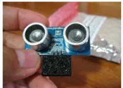
This session will be discussed about the results that have been done for development of sonar sensor system for AUV Application project. First of all, study on the back ground of suggested project. After that, search and get information about the main hardware use in this project. Then, find the datasheet and get the information of the main component use in this project such as PING Ultrasonic Distance Sensor, Proowave Ultrasonic TXR and PIC 16F877A. The Figure 7 shows the PING Ultrasonic Sensor Distance circuit. The PING sensor has a male 3-pin header that function used to supply ground, power and signal. The header may be plugged into a directly into solderless breadboard, or into a standard 3-wire extension cable. Refer to the Figure 8 shows the pin definition of PING ultrasonic distance sensor circuit. Table 2 refers the pin definitions of the circuit.
Figure 8: Pin Definition of PING Ultrasonic Distance TABLE 2.
PIN DEFINITIONS
GND Ground (Vss)
5V 5 VDC (Vdd)
SIG Signal (I/O pin)
A. Developed a Controller Board and Ultrasonic Distance Circuit
Based on the project, the controller board for PIC16F877A is developed. The board is divided into 2 sections which are; the burner section and the controller section. All the distance that detected by the ultrasonic sensor will be displayed on the 2x16 LCD that already attached to the microcontroller board. The size of this board is about; 10cm X 30 cm. Figure 9 shows the circuit of controller board.
Figure 9: Circuit of controller board.
Then, the microcontroller part will be combined with the ultrasonic distance sensor circuit. The ultrasonic sensor will be replaced with the proowave ultrasonic TXR sensor. Figure 10 shows the proowave ultrasonic TXR sensor.
Figure 10: Proowave Ultrasonic TXR B. Design a Flow Chart of Program.
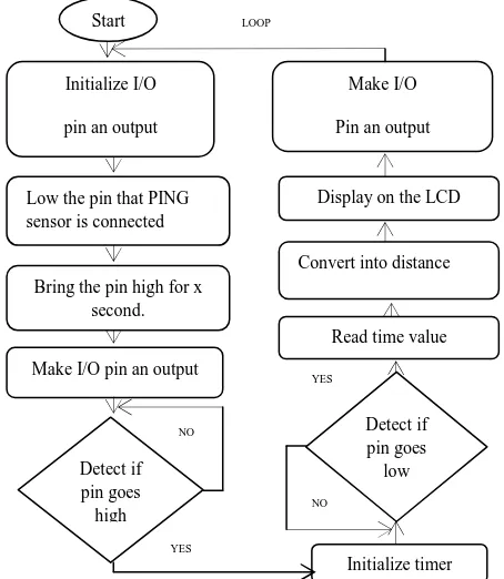
Before start write a program, it is compulsory to design a flow chart based on the program. The purpose to do that is to make sure that the yield of the program is correct. Figure 11 shows of the flow chart of the program.
Figure 11: Idea the Flow Chart of the Program Transmitter Receiver
Start
Initialize I/O
pin an output
Low the pin that PING sensor is connected
Bring the pin high for x second.
Make I/O pin an output
Detect if pin goes high
Initialize timer Detect if pin goes low Read time value Convert into distance Display on the LCD
Make I/O
Pin an output
Burner LCD
NO
NO
YES
C. Prototype of AUV, Ultrasonic Distance Sensor and Controller Board Position.
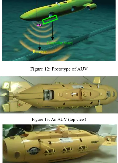
Figure 12 shows the design of the prototype AUV with the position of the sensor and controller board. Refer to the Figure 12, the transmitter and receiver sensor are located at the bottom inside the AUV prototype. Then, the controller board will be place beside the sensor location in a short distance to minimize the usage of wire connection and also can reduce the power loss.Figure 13 and 14 shows the real AUV that will be attached with sonar sensor system.
Figure 12: Prototype of AUV
Figure 13: An AUV (top view)
Figure 14: An AUV (side view) V. CONCLUSION
From this project, a lot of thing that can be learn about the sonar sensor system. Students will be able learn the main theoretical of the sonar sensor system work for underwater. Besides that, student will be able learn how to make a connection of the hardware that use in this project. For the example, the connection between the PIC
microcontroller and the ultrasonic sensor distance circuit. In addition, student also knows how to use the PIC16F877A.
The programming that used MikroC as a compiler will make the students more advanced and more understand how to build a program by using this software. Other things after carry out this project, it can expand the knowledge on wavefront propagation. The designing of the prototype of AUV need to use a SolidWork at a first stage make a student learn a new software that are really important in engineering field.
ACKNOWLEDGEMENT
We wish to express our gratitude to honorable Faculty of Electrical Engineering, Universiti Teknikal Malaysia Melaka especially to higher management for give the financial as well as moral support complete this project successfully.
REFERENCES
[1] Chuhran, Christopher D., “Obstacle Avoidance Control In The
Vertical Plane For The REMUS Autonomous Underwater Vehicle”
MSME Thesis, Naval Postgraduate School, Monterey, CA. ,2005. [2] Furukawa, Tyler H. “Reactive Obstacle Avoidance For
The REMUS Autonomous Underwater Vehicle Utilizing A Forward Looking Sonar”, MSME Thesis , Naval Postgraduate School,
Monterey, CA., 2006.
[3] R. Kuc and M. W. Siegel, “Physically based simulation
model for acoustic sensor robot navigation,” IEEE
Trans Pattern Anal. Machine Intell., vol. PAMI-9, no. 6, pp. 766-778, Nov. 1987.
[4] J. Budenske and M. Gini, “Why is it so difficult for a robot to pass
through a doorway using ultrasonicsensors?,” IEEE Conference on
Robotics and Automation, San Diego CA, 1994
[5] H. Akbarally and L. Kleeman, "3D robot sensing from sonar and
vision", IEEE International Conference on Robotics and Automation
1996, Minneapolis, Minnesota, April 1996.
[6] Healey, A. J., "Obstacle Avoidance While Bottom Following for the
REMUS Autonomous Underwater Vehicle" Proceedings of the
IFAC-IAV 2004 Conference, Lisbon, Portugal. http://web.nps.navy.mil/~me/healey/papers/IAV2004.pdf [accessed 10 September 2009]
[7] D. J. Danko, “Autonomous Underwater Vehicle Obstacle Detection
And Assessment Using Forward Looking Sonar” MSME Thesis
Naval Postgraduate School, September 2004
http://www.cs.nps.navy.mil/research/auv/theses/danko/04Sep_Danko .pdf [accessed 6 August 2009]
[8] Horner, D. P., Healey, A. J., “AUV Experiments in Obstacle
Avoidance”, Proceedings of IEEE Oceans Conference, 2005.
http://web.nps.navy.mil/healey/papers/Oceans2005.pdf [accessed 8 August 2009]
[9] Healey, A. J., Horner, D. P., "Collaborative Vehicles in Future Naval
Missions, Obstacle Detection and Avoidance ", Keynote Paper,
Proceedings of the IFAC Conference on Maeuvering and Control of Marine Craft, MCMC, 2006, Lisbon, Portugal, September 20-23, 2006 http://web.nps.navy.mil/~me/healey/papers/MCMC06.pdf [accessed 10 October 2009]
[10] Healey, A. J., “Guidance Laws, Obstacle Avoidance , Artificial
Potential Functions”, Chapter 3, Advances in Unmanned Marine
Vehicles, IEE Control Series 69, Eds. Roberts and Sutton, March, 2006
http://web.nps.navy.mil/~me/healey/papers/IEEBOOKCHPT.pdf [accessed 12 October 2009]
Transmitter
Receiver