162
SOUND TRANSMISSION LOSS OF A DOUBLE-LEAF
SOLID-MICROPERFORATED PARTITION UNDER
NORMAL INCIDENCE OF ACOUSTIC LOADING
A.Y.ISMAIL,A.PUTRA AND MD.R.AYOB
Faculty of Mechanical Engineering, University Technical Malaysia Melaka (UTeM), Hang Tuah Jaya, Durian Tunggal 76100 Melaka, Malaysia.
ABSTRACT: The micro-perforated panel (MPP) is recently well-known as an alternative
‘green‘ sound absorber replacing the conventional porous materials. Constructed from a solid panel which provides a non-abrassive structure and also an optically attractive surface, there gives a feasibility to implement such a panel inside a vehicle cabin. This paper is the preliminary study to investigate the sound transmission loss (TL) of a solid panel coupled with a micro-perforated panel to form a doube-leaf partition which is already known as a lightweigth stucture for noise insulation in vehicles and buildings. The mathematical model for the TL subjected to normal incidence of acoustic excitation is derived. The results show that its performance substantially improves at the troublesome frequency of mass-air-mass resonance which occurs in the conventional double-leaf solid partition. This is important particularly for the noise source predominant at low frequencies. This can also be controlled by tuning the hole size and number as well as the air gap between the panels.
ABSTRAK: Panel bertebuk mikro (micro-perforated panel (MPP)) kebelakangan ini
dikenali sebagai alternatif penyerap bunyi yang mesra alam menggantikan bahan berliang lazim. Dibina daripada satu panel padu yang memberikan satu struktur tak lelas dan juga satu permukaan yang menarik, ia memberikan kemungkinan penggunaan panel tersebut di dalam kabin kenderaan. Tesis ini merupakan kajian permulaan dalam mengkaji hilang pancaran bunyi (sound transmission loss (TL)) oleh satu panel padu yang digandingkan dengan satu panel bertebuk mikro. Kaedah ini menghasilkan satu sekatan lembar kembar yang sememangnya dikenali sebagai struktur ringan penebat bunyi di dalam kenderaan dan bangunan. Model matematik diterbitkan untuk TL tersebut dengan menjalankan pengujaan akustik yang tuju normal. Keputusan menunjukkan bahawa prestasi meningkat dengan ketara pada frekuensi yang susah semasa resonans jisim-udara-jisim berlaku di dalam sekatan padu lembar kembar lazim. Ini penting terutamanya untuk sumber bunyi yang pradominan pada frekuensi rendah. Ia juga boleh dikawal dengan menalakan saiz dan jumlah lubang serta luang udara di antara panel-panel tersebut.
KEYWORDS: sound transmission loss; double-leaf; partition; micro-perforated panel
1.
INTRODUCTION
163
known method for reducing the noise is by installing a partition panel. In general, the partition has a main function to reflect most of the noise and transmit the rest. This is caused by large changes of acoustic impedance in the transmission path created by the partition. A double-leaf partition is known as the lightweight structures in a vehicle such as car doors, train walls or aircraft fuselages. This double-panel is found to increase the transmission loss significantly compared with the single panel partition [1]. However, for noise source predominantly dominates at low frequencies, a double-partition gives a poor performance due to the so-called mass-air-mass resonance. The experimental results for sound transmission loss (TL) of single and double-leaf partitions can be seen in Fig.1. This presents that the double-leaf gives the troublesome resonance frequency for noise insulation at around 100 Hz.
Fig. 1: Comparison of sound transmission loss between single and double-leaf partition [2]. Several works have been done to improve the performance of the double-leaf partition including to overcome the problem at mass-air-mass resonance. This includes the introduction of a Hemholtz resonator between the gap [2], by embedding long T-shaped resonators along the edge of the double panel partition [3], by placing loudspeaker and installing actuator between the gap to actively control the acoustic mode [4] and filling the absorbent material inside the gap [5].
164
Many studies have been done to improve the performance of MPP in terms of its sound absorption including by coupling it into a double-leaf system [8], increasing the thickness to obtain better mechanical structure properties [9], modifying the hole shape [10] and partitioning the back cavity [11].
This paper is the preliminary study to investigate the performance of a solid plate coupled with a MPP in terms of its sound transmission loss (TL). The use of the MPP in this system is to provide a good sound absorption inside the cabin. On the other hand, the presence of the MPP is also expected to overcome the phenomenon of the mass-air-mass resonance for a double-leaf. The viscous force of the air flow inside the hole creates a friction force between the air and the inner wall of the holes. This becomes an additional damping which reduces the resonances of the system. For the rest of this paper, the system is referred as the solid-microperforated partition (SMPP) system. In the next section, the mathematical model of the TL for the SMPP system is derived.
2.
THEORY
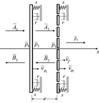
Figure 2 shows a mechanical system of a SMPP with uniform, unbounded and non-flexible panels having mass per unit area µ supported by viscous dampers r and elastic suspensions s impinging by normal incidence of sound wave.
The incident and reflected sound pressure with frequency
at the solid (left) panel are given byjkx
i Ae
p ~1
~ (1)
pr B1ejkx
~
~ (2)
where k /cis the acoustic wave number and cis the speed of sound. The curl sign indicates complex number.
Using Euler equation v~1/ j
dp/dx
at x = 0- for Eq. (1) and Eq. (2), the particle velocity can be written as~ 1
A~1 B~1
c
v
(3)
165
Fig. 2: Mechanical system of a double-solid-microperforated partition.
Since the left panel is solid, the particle velocity along the plate surface v~ is same with panel velocity v~p. Eq. (3) can be rearranged as
1 1
~ ~ ~
1 A B
v
Zf p (4)
where Zf c is the impedance of the air and 1 ~
p
v is the solid panel velocity. The acoustic pressure acting on the solid panel surface ~p1and ~p2 at x = 0 and on the perforated panel surface at x = d are given by
r
i p
p B A
p ~ ~ ~ ~
~
1 1
1 (5)
2 2 2
~ ~
~ A B
p (6)
jkd jkd
e B e
A
p3 2 2
~ ~
~ (7)
v Zf t
p
~ (8)
The mean particle velocity v in Eq. (8) is obtained due to the presence of holes in the right panel. The particle velocity is no longer the same as the panel velocity, but it now includes the effect of the particle velocity inside the holes. According to Takahashi and Tanaka [12], this is given by
fp v
v
v ~ 1 ~
2
(9)
where v~f is the fluid velocity inside the holes, 2 ~
p
v is the right panel velocity and is the perforation ratio.
166 impedance Zo,R represents the viscous effect of air interaction with the panel surface in the
hole and imaginary part Z~o,I represents the acoustic reactance from the inertia of the air inside the holes. The following equation of the net force acting on the plate can be expressed as
v v
Z v pZo,R ~f ~p ~o,I~f
2 (12)
Re-arrange Eq. (12) and substitute to Eq. (9) gives the mean particle velocity as a function of the pressure difference p
Z
The equation of motion for the right panel due to the acoustic loading is given by
2
where the second term on the right hand side of Eq. (14) is the viscous force inside the hole. Re-arrange Eq. (14) and using Eq. (12) yields
2
where is the modified panel impedance due to the perforations given by
Equation (7) can be expanded into
A B
kd j
A B
kd167
Again using Euler equation for Eq. (7) and substituting Eq. (6) yields the pressure at x = 0+ (right side surface of the solid panel)
The pressure difference at the perforated panel is
t p p p ~3~
(21)
By substituting Eq. (20) and Eq. (8) into Eq. (21) gives
Substituting Eq. (5), Eq. (19) and Eq. (24) into Eq. (18) yields the incident pressure
168 By substituting the velocity ratio from Eq. (23)
and the transmission loss is given by
log 10
TL (29)
3.
RESULTS AND DISCUSSION
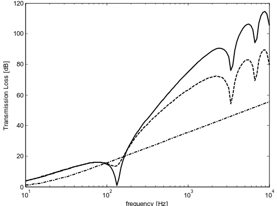
Figure 3 shows the theoretical results of the TL for the conventional solid double-panel (SDP) and SMPP. The result for the single panel is also presented for comparison. The calculation is made for 1 mm thick steel plate with density 7800 kg/m3. The material properties of the MPP as the rear panel is the same, with hole diameter do = 0.1 mm, 50 mm
air gap and perforation ratio 0.5%. It can be seen that at low frequencies below 100 Hz, both results give identical values.
169
Around 150 Hz the common problem of ‘drop’ value for the conventional SDP occurs due to the system resonance. The double-leaf shows its superiority over the single panel across the frequency range except at the resonance. Around this particular frequency, both the panels and air inside the cavity move in phase which is then known as ‘mass-air-mass’ resonance. The transmission loss is found to drop to almost 0 dB which indicates a bad performance for a noise barrier especially for a noise dominating around this frequency. The dips around 3.5 and 7 kHz are the cavity resonances which occur at the corresponding acoustic wavelength of nλ = 2d with n is any non-zero positive integer.
For the SMPP, a better performance is obtained around this troublesome resonance frequency. The air pressure passes through the hole creates a viscous shear stress due to friction between the air and the wall inside the holes. This friction force which has opposite direction to the motion of the panel gives additional damping to the cavity that reduces the coupling between the structural and the acoustic cavity modes. However, above this resonance, the TL from SMPP is lower than that from the SDP.
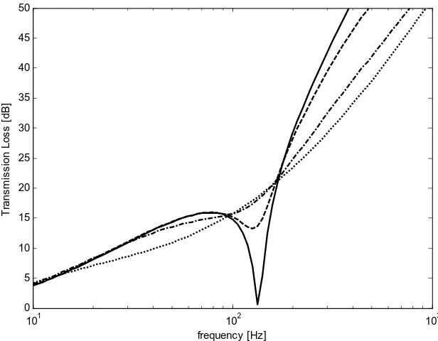
Fig. 4: Sound transmission loss of SMPP with different hole diameter for 0.5% perforation ratio and 50 mm air gap under normal incidence of acoustic loading
(—SDP, – – do = 0.1 mm, – • – do = 0.2 mm, ٠٠٠ do = 0.4 mm).
Figure 4 presents the results for SMPP with different hole diameters and constant perforation ratio of 0.5% and gap distance 50 mm. This is plotted up to 1 KHz to focus only around the resonance region. The SDP decreases the TL by roughly 15 dB in average around the resonance. However, it can be seen that the use of a MPP for the rear panel improves the TL around the resonance. The improvement can be achieved by increasing the hole size, but in consequence, decreases the performance above the resonance. It can also be seen that doubling the diameter from 0.2 mm to 0.4 mm gives almost no effect on the TL at the resonance.
101 102 103
0 5 10 15 20 25 30 35 40 45 50
frequency [Hz]
T
ra
n
s
m
is
s
io
n
L
o
s
s
[
d
B
170
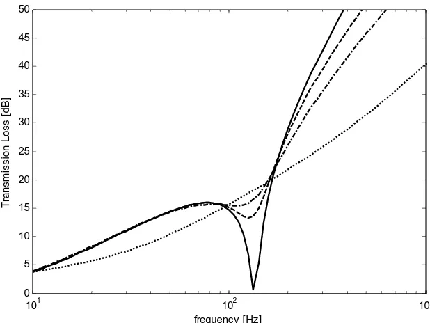
Figure 5 plots the results for constant hole diameter by varying the perforation ratios. The improvement of TL around the mass-air-mass resonance can also be seen by increasing the perforation ratio.
The effect of the air gap is presented in Fig. 6. It can be seen that the decrement of the air gap increases the resonance and at the same time also reduces the ‘drop value‘ significantly. The TL at the mass-air-mass resonance improves as the air gap is reduced. At high frequencies, the TL reduces as the gap increases.
For clarity of analysis, the level of improvement or decrement of the TL can be represented by the insertion gain (IG) i.e. the ratio of the transmitted power after to before the introduction of micro-holes at the rear panel which is given by
sdp smpp
sdp smpp
TL TL
log 10
IG
(30)
where TLsmpp is the transmission loss of the SMPP and TLsdp is for the SDP.
Fig. 5: Sound transmission loss of SMPP with different perforation ratios for 0.1 mm hole diameter and 50 mm air gap under normal incidence of acoustic loading
(—SDP, – – τ = 0.5%, – • – τ = 1%, ٠٠٠τ = 1.5%).
101 102 103
0 5 10 15 20 25 30 35 40 45 50
frequency [Hz]
T
ra
n
s
m
is
s
io
n
L
o
s
s
[
d
B
171
Fig. 6: Sound transmission loss of SMPP with different air gaps for 0.1 mm hole diameter and 0.5% perforation ratio under normal incidence of acoustic loading
(—SDP, – –d = 10 mm, – • –d = 20 mm, ٠٠٠d = 40 mm).
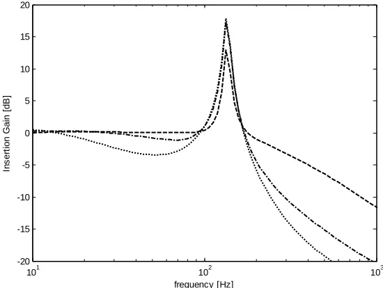
Figure 7 shows the IG for SMPP with different diameters as in Fig. 3. It can be seen that the improvement around the resonance is about 15-18 dB. Deterioration above the resonance can be seen to increase with frequency.
Fig. 7: Insertion gain of SMPP with different hole diameters for 0.5% perforation ratio and 50 mm air gap under normal incidence of acoustic loading
( – – do = 0.1 mm, – • – do = 0.2 mm, ٠٠٠ do = 0.4 mm).
101 102 103
0 5 10 15 20 25 30 35 40 45 50
frequency [Hz]
T
ra
n
s
m
is
s
io
n
L
o
s
s
[
d
B
]
101 102 103
-20 -15 -10 -5 0 5 10 15 20
frequency [Hz]
In
s
e
rt
io
n
G
a
in
[
d
B
172
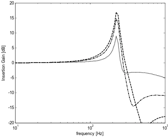
Figure 8 shows the IG for different perforation ratios. Same with previous results, the improvement can be seen by 15-18 dB at 150 Hz.
The IG for different air gaps are also presented in Fig. 9. It can be seen that doubling the air gap reduces the TL at the resonance by roughly 4 dB. However, as in Figs. 7 and 8, the improvement is only around the mas-air-mass resonance.
Fig. 8: Insertion gain of SMPP with different perforation ratios for 0.1 mm hole diameter and 50 mm air gap under normal incidence of acoustic loading
(– – τ = 0.5%, – • – τ = 1%, ٠٠٠τ = 1.5%).
Fig. 9: Insertion gain of SMPP with different air gaps, for 0.1 mm hole diameter, 0.5% perforation ratio under normal incidence of acoustic loading
(– –d = 10 mm, – • – d = 20 mm, ٠٠٠d = 40 mm).
101 102 103
-20 -15 -10 -5 0 5 10 15 20
frequency [Hz]
In
s
e
rt
io
n
G
a
in
[
d
B
]
101 102 103
-20 -15 -10 -5 0 5 10 15 20
frequency [Hz]
In
s
e
rt
io
n
G
a
in
[
d
B
173
4.
CONCLUSION
Preliminary study on the possibility to apply the MPP as the noise barrier in a double-leaf partition has been presented. In order to improve the poor performance at the resonance for transmission loss of the conventional double-leaf, the presence of micro-perforated holes in the rear panel is found to be effective. However, the improvement only happens at a very narrow frequency band around the mass-air-mass resonance. It is found that this improvement can be increased by increasing the hole size or the perforation ratio and by reducing the air gap. On the other hand, application of the MPP seems to sacrifice the performance at high frequencies. Nevertheless, this is still beneficial especially for the noise source dominating at low frequencies. Moreover, the model proposed assumes normal incidence of sound excitation. For more real application, which is diffuse field, the effect will be greater in terms of the frequency range. This will be investigated on the future work.
ACKNOWLEDGEMENT
This research is funded by The Fundamental Research Grant Scheme (FRGS) of the Ministry of Higher Education (MOHE) Malaysia at the University Technical Malaysia Melaka.
REFERENCES
[1] Fahy, F., Gardonio, P., Sound and Structural Vibration : Radiation, Transmission and response. Academic Press, 2007.
[2] Mao, Q., Pietrzko, S., “Control of sound transmission through double wall partition using optimally tuned Hemholtz resonators” Applied Acoustics, 2005.
[3] Li, D., Zhang, X., Cheng, L., and Yu, G., “Effectiveness of T-shaped acoustic resonators in low frequency sound transmission control of a finite double-panel partition.” Journal of Sound and Vibration, Vol:329, pp. 4740-4755, 2010.
[4] Li and Cheng, “Mechanism of active control of sound transmission through a linked double wall system into an acoustic cavity,” Applied Acoustics, Vol : 69, pp. 614-623, 2008.
[5] Alba, J., Ramez, J., and Snachez, V., “Improvement of the prediction of transmission loss of double panel with cavity absorption by minimization techniques” Journal of Sound and Vibration, Vol:273, pp.793-804, 2004.
[6] Maa, D., “Theory and design of microperforated panel sound absorbing construction (in chinese).” Scientica Sinica, Vol:18, pp.55-71, 1975.
[7] Fuchs, H. V., Zha, X., “Micro-perforated structures as sound absorber – A review and outlook” Acta Acustica united with Acustica, Vol:92, pp.139-146, 2006.
[8] Sakagami, K., Morimoto, M., and Koike, W., ”A numerical study of double leaf microperforated panel absorber.” Applied Acoustics, Vol:67, pp.609-619, 2006.
[9] Pfretzschner, J. and Cobo, P., “Microperfoated insertion units : An alternative strategy to design microperforated panels.” Applied Acoustics, Vol:67, pp.62-73, 2006.
[10] Sakagami, K., Morimoto, M., Yairi, M., and Minemure, A., “A pilot study on improving the absorptivity of a thick micoperforated panel absorber,” Applied Acoustics, Vol:60, pp.179-182, 2008.
[11] Liu and Herrin, “Enhancing microperforated panel attenuation by partitioning the adjoining cavity,” Applied Acoustics, Vol:71, pp.120-127. 2010.
174
NOMENCLATURE
c Sound speed in air m/s
d Gap distance m
do Hole diameter m
j Imaginary part -
k Wavenumber rad/m
p Acoustic pressure N/m2
Pressure difference N/m2
r Damping coefficient per unit area Ns/m
s Stifness per unit area N/m
t Panel thickness m
TL Transmission loss dB
va Air viscosity kg/s.m
Particle velocity m/s
Panel velocity m/s
Z Total acoustic impedance Ns/m3
Zo Hole impedance Ns/m3
Zo,R Real part of hole impedance Ns/m3
Zo,I Imaginary part of hole impedance Ns/m3
zf Fluid impedance Ns/m3
µ Mass per unit area kg/m2
ω Angular frequency rad/s
ρ Air density kg/s.m
τ Transmission coefficient -
p
v~
![Fig. 1: Comparison of sound transmission loss between single and double-leaf partition [2]](https://thumb-ap.123doks.com/thumbv2/123dok/592150.70703/4.612.173.457.223.449/fig-comparison-sound-transmission-loss-single-double-partition.webp)