1086 lightweight structure for noise insulation, such as in car doors, train bodies, and aircraft fuselages. Unfortunately, the insulation performance deteriorates significantly at mass-air-mass resonance due to coupling between the panels and the air in the gap. This paper investigates the effect of a micro-perforated panel (MPP), inserted in the conventional double-panel partition, on sound transmission loss at troublesome resonant frequencies. It is found that the transmission loss improves at this resonance if the MPP is located at a distance of less than half that of the air gap. A mathematical model is derived for the diffuse field incidence of acoustic loading.
Keywords: Transmission loss; double-panel; noise; MPP; acoustics.
INTRODUCTION
A double-leaf structure is a common structural design in many engineering applications. Body structures of cars, trains, and airplanes, as well as the walls of buildings are some examples of double-leaf partitions in practice. The double-leaf has been found to be a better noise barrier compared with the single-leaf. However, there remains a problem with the double-panel, which is the weak sound transmission loss (STL) performance at low frequencies due to the “mass-air-mass” resonance. At this frequency range, this causes the double-leaf to lose its superiority over the single-leaf structure (Fahy and Gardonio, 2006). Several works have been published on attempts to overcome this problem. This includes the application of absorptive materials inside the gap of a double-leaf to increase damping (Tang et al., 1998, Bravo et al., 2002). This treatment was found to be effective in increase STL at low frequency, including that of the mass-air-mass resonance. Another work suggested installing Hemholtz resonators in the air gap (Mao and Piertzko, 2005). This resonator acts like a single-degree of freedom system, the natural frequency of which depends on its geometry. It is found that by optimally tuning the resonator, the STL at resonance is improved significantly.
1087
the actuator to the panels, both strategies gave effective reduction of sound transmission. Similarly, a long T-shaped resonator was embedded along the edge of the double panel to control actively the acoustic path inside the gap (Li et al., 2010). This was also been found effective in increasing STL at an even broader frequency range.
In 1975, Dah You Maa in China found that when a thin panel with sub-millimeter-sized holes was introduced and located in front of a rigid panel with an air gap, the micro-perforated panel (MPP) acts as a sound absorber following a Helmholtz resonator mechanism. The diameter of the holes must be within the range 0.05−1 mm and the perforation ratio must be between 0.5% and 1.5% for optimum absorption (Maa, 1975). As the MPP is made from a panel, it provides several advantages, such as being non-fibrous, non-abrasive, and non-polluting. Several works have been conducted concerning the improvement of sound absorption performance of the MPP, e.g., by arranging it to be a double-leaf (Sakagami et al., 2006), by increasing its thickness (Pfretzner and Cobo, 2006), and by modifying its hole geometry (Sakagami et al., 2008). This paper proposes the insertion of an MPP within a double-panel partition. The proposed system might be important for a condition where any abrasive and toxic material, such as commercial glass wool and glass fiber cannot be presented for health reasons. The next section describes the derivation of the mathematical model and the simulation results that show the effect of the MPP insertion, in terms of the location of the MPP in the gap, as well as its hole size and perforation ratio on the performance of the sound transmission loss, particularly at the mass-air-mass resonance.
GOVERNING EQUATIONS
Propagating Acoustic Pressure
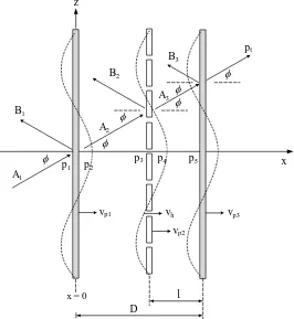
Figure 1 shows a mechanical system consisting of double solid panels with an MPP inserted in between (abbreviated here as DL-MPP), which is excited by an oblique incidence of sound with an arbitrary angle φ. The solid panels are separated by distance
D and the MPP is located at distance l from the back solid plate. Each of the unbounded solid and MPP panels has mass per unit area M and m, respectively. The component of the incident wavenumber vector directed parallel to the panel is kz= ksinφ. As the panel
is uniform and infinite, the flexural or bending wave induced in the panel must also have the same wavenumber kz. The incidence and reflected pressures upon the panel are
given by: panel surface p2 can be obtained. Note that for the analysis of propagating pressure in
1088
velocity v and the sound pressure exciting the panel can be obtained by using the Euler equation v = −1/jρω(dp/dx). For both surfaces ofeach panel, at x = 0 for the front panel,
for the solid plate, the mean particle velocity on its surface is equal to the velocity of the panel v = vp. This is valid for light fluid such as air, but not for heavy media such as
water. For convenience, the distance between the panel is assumed much smaller compared with the acoustic wavelength (kd < < 1). The cavity pressures can therefore be assumed uniform between each gap:
p2≈ p3 = A2 + B2 = pb (8)
1089 Eq. (5) can be expanded to:
zf vm= (A2,3[cos k(D −l)– jsin k(D −l)] − B2,3[cos k(D −l) + jsin k(D −l)]) cos φ
(10)
By using Eq. (8), Eq. (10) can be rewritten as:
zf vm= A2 − B2 − jk(D − l) cos φ pb (11)
zf vm= A3 − B3 − jk(D − l) cos φ pc (12)
As the cavity pressure is uniform, the pressure between each gap can thus be expressed in terms of the front panel velocity:
pb= zf(vp1 − vm)/jk(D − l) cos φ (13)
pc= zf(vm− vp1)/ jkl cos φ (14)
Hole Impedance and Mean Particle Velocity
As the acoustic pressure impinges on the MPP, the air particles penetrate the holes and excite the remaining solid surface of the panel. The combination between the panel velocity and particle velocity inside the holes creates the mean particle velocity given by Takahashi and Tanaka (2002):
vm= vp(1 − ) + vh (15)
where vh is the particle velocity inside the hole and is the perforation ratio. The air
inside the holes moves like a moving piston owing to its inertial property. At the same time, the air also interacts with the inner surface of the holes creating a friction force. These mechanisms are represented by the hole impedance. According to Maa (1975), this is given by:
Zo = Zo,R+ Zo,I (16)
with
Zo,R= 32υat[(1+Xo2/32)1/2 + (1.71Xo/8)do/t] /do2 (17)
Zo,I= jωρt [1+(9 + Xo2/2)-1/2 +0.85do/t] (18)
where Xo= (do/2) (ωρ/υa)1 /2
, dois the hole diameter, t is the MPP thickness, and υa is the
viscosity of air, i.e., 1.8 × 10⁻⁵ Ns/m2. The resistive or real part of the impedance Zo,R
represents the viscous effects, i.e., the interaction of the fluid particle with the wall inside the holes, while the reactive or imaginary part Zo,I represents the acoustic
1090
Zo,R(vh − vp) + Zo,I vh = Δp (19)
Substituting Eq. (15) into Eq. (19) gives:
vm= γvp + Δp/Zo (20)
where γ = 1−( Zo,I/Zo) is the complex non-dimensional term.
Sound Transmission Loss
The equation of motion for the solid back panel is given by:
zp3vp3 = pc– pt (21)
where zp3 = −j(Gk4sin4φ−Mω2)/ω is the bending mechanical impedance with G =
Et3/12(1−ν), which is the bending stiffness of the panel, E is the Young’s modulus, and
ν is the Poisson’s ratio. Substituting both pt in Eq. (7) and pc in Eq. (14) into Eq. (21)
and then dividing both sides by vp3 yields the panel velocity ratio:
vp2/vp3 = [1 + jkl cos φ(1 +zp3 cos φ/zf)]/(γ+zp2/Z) (22)
The equation of motion for the MPP is expressed as:
zp2vp2= Δp (23)
where zp2 = −j(Gk4sin4φ−mω2)/ω. Substituting Eqs. (13), (14) and (20) into Eq. (23)
and again dividing both sides by vp3 yields:
vp1/vp3 = (vp2/vp3) (jk(D − l)zp2zf) + [1 + jkD(1 +zp3zf )] (24)
It can be seen that the velocity ratio of the solid panels vp1/vp3 depends on the
location of the MPP within the air gap.
The equation of motion for the front solid panel (similar to Eqs. (21) and (23)) is expressed as:
zp1vp1 = p1– pb (25)
By substituting Eqs. (3), (13) and (14) into Eq. (25), the ratio of incident to transmitted pressure is given as:
pi/pt = ((vp1/vp3)[1 + jk(D − l) cos φ(1 +zp1/zf)]
−(vp2/vp3) (γ +zp2/Z)) cos φ /j2k(D − l) (26)
The case for normal incidence of acoustic loading can be obtained by setting
1091
As for plane waves, the sound power W is proportional to the sound intensity I, which is simply a ratio of the squared magnitude sound pressure to the air impedance, i.e., I = |p2| /zf. The transmission coefficient is therefore given by =|pt/pi|2. For diffuse
fields, this can be governed by integrating over angles of incidence, which is given by (Fahy and Gardonio, 2007):
t d = t (j )sin 2j dj
0 p /2
ò
(27)The transmission loss in dB unit is:
STL = 10log10(1/ ) (28)
ANALYTICAL RESULTS
Figure 2 shows the sound transmission loss for the case of normal incidence for partitions consisting of DL [1], triple-leaf (TL), and DLMPP for an MPP located exactly in the middle of the two panels (l = 0.5D) for an air gap D = 100 mm. The mass-air-mass resonance of the DL can be seen to occur around 170 Hz, where the STL is nearly 0 dB. The presence of the MPP in this case does not affect this resonance because this corresponds to the gap of the double solid plates. By inserting another solid panel between the double-panel (TL), the second resonance appears at 280 Hz, which is due to the gap between the middle and the back panel. This worsens the problem, although the STL at mid-high frequency increases significantly owing to the increase of mass within the system.
Figure 2. Sound transmission loss of DL (—), TL (−・−) and DLMPP
1092
As the objective is to improve the STL of the conventional double-leaf partition (DL) at the mass-air-mass resonance, Figure 3 shows the STL for the DL and DLMPP for different locations of the MPP relative to the solid plate. This is plotted for the case of diffuse field incidence, which can be seen to yield a broader frequency range of resonance effects due to the summation of resonance dips at various angles of incidences. This shows that for other locations of the MPP, as the MPP shifts closer to the panel either at the front or to the back solid panel, the STL can be observed to increase at the resonance. The additional damping, due to the viscous force in the MPP holes, influences the air layer in front of the solid plate, which breaks the coupling between the solid panels and the air.
Figure 3. Sound transmission loss of DL (—) and DLMPP for different locations of MPP in the gap subjected to diffuse field incidence of acoustic loading (do= 0.1 mm,
= 1.5%).
1093
Figure 4. Sound transmission loss of DLMPP for different hole diameters ( = 0.5%) subjected to diffuse field incidence (l = 0.1D).
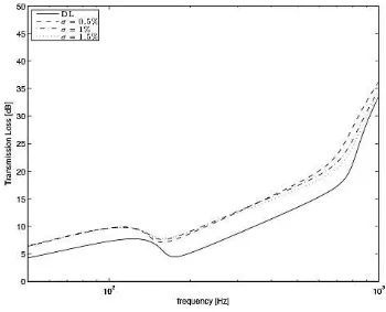
Figure 5. Sound transmission loss of DLMPP for different perforation ratios (do= 0.1
1094
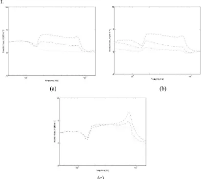
For clarity of the analysis, the level of improvement of the TL (around the resonance) can be represented by the insertion loss, i.e., the ratio of the transmitted sound power before and after the MPP insertion, which is given by:
F =10 log t DL t DLMPP
æ
è
ç ö
ø
÷=STLDLMPP- STLDL (29)
where STLDLMPP is the transmission loss of the DL-MPP and STLDL is for the
double-leaf.
(a) (b)
(c)
Figure 6. Insertion loss of DLMPP system with different MPP parameters: (a) locations in the gap (do= 0.1 mm, = 1.5%, −−l = 0.1D,
- ×-
l = 0.25D, l = 0.5D), (b) holediameters (l = 0.1D, = 1.5%, −−do= 0.1 mm,
- ×-
do= 0.2 mm, do= 0.4 mm), and(c) perforation ratio (l = 0.1D, do= 0.1 mm, −− = 0.5%,
- ×-
= 1%, = 1.5%).1095
CONCLUSIONS
Models of sound transmission loss of a DLMPP system under diffuse field incidences of acoustic loading have been developed. It is found that the MPP insertion reduces the effect of resonance found in the conventional double-leaf partition. However, this is only effective when the MPP distance is less than half of the air gap and it improves as it approaches the solid plate. Reducing the size of the hole improves the STL at resonance, while changing the perforation ratio gives almost no effect on the STL performance at resonance. The model can be used for designing a multi-layer partition where problems of mass-air-mass resonance might be experienced due to a predominantly low frequency noise source.
ACKNOWLEDGMENTS
The authors gratefully acknowledge the financial support for this project by The Ministry of Higher Education Malaysia (MoHE) under Fundamental Research Grant Scheme, FRGS/2010/FKM/TK02/3-F0078.
REFERENCES
Bravo, J.M., Sinisterra, J., Uris, A., Llinaresand, L. and Estelles, H. 2002. Influence of air layers and damping layers between gypsum boards on sound transmission. Applied Acoustics, 63: 1051-1059.
Fahy, F.J. and Gardonio, P. 2006. Sound and structural vibration: radiation, transmission and response. London: Academic Press, 2nd edition.
Li, D., Zhang, X., Cheng, L. and Yu, G. 2002. Effectiveness of T-shaped acoustic resonators in low-frequency sound transmission control of a finite double-panel partition. Journal of Sound and Vibration, 329: 4740-4755.
Li, Y.Y. and Cheng, L. 2008. Mechanism of active control of sound transmission through a linked double wall system into an acoustic cavity. Applied Acoustics, 69: 614-623.
Maa, D.Y. 1975. Theory and design of microperforated panel sound absorbing constructions (in Chinese). Scientia Sinica, 18: 55-71.
Mao, Q. and Pietrzko, S. 2005. Control of sound transmission through double wall partition using optimally tuned Hemholtz resonators. Applied Acoustics, 91: 723-731.
Pfretzner, J. and Cobo, P. 2006. Microperforated insertion units: An alternative strategy to design microperforated panels. Applied Acoustics, 67: 62-73.
Sakagami, K., Morimoto, M. and Koike, W. 2006. A numerical study of double-leaf microperforated panel absorbers. Applied Acoustics, 67: 609-619.
Sakagami, K., Morimoto, M., Yairi, M. and Minemura, A. 2008. A pilot study on improving the absorptivity of a thick microperforated panel absorbers. Applied Acoustics, 60: 179-182.
Takahashi, D. and Tanaka, M. 2002. Flexural vibration of perforated plates and porous elastic materials under acoustic loading. Journal of The Acoustical Society of America, 112: 1456-1464.