OBJECT LOCATOR FOR PEOPLE WITH DEMENTIA (DEMICATOR)
JOYE TER JI-XI
This Report Is Submitted In Partial Fulfillment Of Requirements For The Bachelor Degree of Electronic Engineering (Industrial Electronics) with
Honours
Faculty of Electronic and Computer Engineering Universiti Teknikal Malaysia Melaka
v
vi
ACKNOWLEDGEMENT
I would like to take the opportunity to express my heartfelt gratitude to the
people who helped me in making this project a success.
First and foremost, I would like to thank my supervisor, Associate Professor
Tan Kim See for his invaluable guidance and advice. His support and encouragement
brought me on the right path especially in times of need, motivating me to carry on
with the project even when things look unsure at times, Also, my heartfelt
appreciation to my co-supervisor, Dr Kok Swee Leong, for without his help, I would
not have been able to make tremendous progress in this project.
In addition, I would like to say a big thank you to my housemates and my
parents for all their wonderful support. They had given me a lot of feedback and
suggestions, some of which became the inspiration of the features of my product.
Without their unceasing words of encouragement, the project could not have been
what it is today.
Lastly, I would like to thank my course-mates, Sau Seong and Ee Leng for
their time in helping and showing me how to solve some difficult circuit problems.
Their patience in answering my never-ending questions and their selfless ways in
helping me throughout this semester is one of the many the factors that help me to
vii
ABSTRACT
Misplacing small but essential items, such as keys, wallets and medicine
container is not uncommon among people who are at a certain age or state of health.
Senior citizens with poor short term memory and those who are affected by memory
impairment are the main concern, such as those suffering from Dementia syndrome.
Sometimes, during emergency, it can be a matter of life or death if the keys to the
main door cannot be found in time. This project purpose is to come up with an
efficient electronic locator to provide a solution to the stated problem above. The
design of the locator system, named DemiCator, comprise of a base station, remote
control and five receiver tags which are attached to the missing items. So if a person
wishes to find the item which has been misplaced, they can simply carry the remote
control around to locate the keys, or fix it on the at the wall to locate the medicine.
The corresponding tags will indicate the position to the users. If the remote control
gets misplaced, user can use the base station to locate the remote control. The base
viii
ABSTRAK
ix
TABLE OF CONTENT
CHAPTER TITLE PAGE
PROJECT TITLE i
VERIFICATION FORM ii
DECLARATION iii
DEDICATION v
ACKNOWLEDGEMENT vi
ABSTRACT vii
ABSTRAK viii
TABLE OF CONTENT ix
LIST OF TABLE xii
LIST OF FIGURES xiii
LIST OF ABBREVIATIONS AND
SYMBOLS xv
I INTRODUCTION
1.1 What is Dementia? 1
1.2 Project Background 2
1.3 Objectives 4
1.4 Problem Statement 4
1.5 Scope of Work 5
1.5.1 Base Station 5
1.5.2 Remote Control 6
1.5.3 Tags Receiver 6
1.6 Project Methodology 7
1.6.1 Flow Chart Process Detail 7
x
1.6.1.2 Literature Review 8
1.6.1.3 Construction of Prototype 8
1.6.1.4 Finalization 8
1.6.2 Report Structure 10
1.6.2.1 Chapter 1 - Introduction 10
1.6.2.2 Chapter 2 - Literature Review 10 1.6.2.3 Chapter 3 - Project
Methodology 10
1.6.2.4 Chapter 4 - Results and
Discussions 10
1.6.2.5 Chapter 5 - Conclusion and
Recommendation 11
II LITERATURE REVIEW
2.1 Survey Concerning Misplaced Item 12
2.1.1 Conclusion 14
2.2 Prompting People with Dementia to Carry
Out Tasks. 14
2.2.1 Method 14
2.2.2 Early Findings 15
2.2.3 Conclusion and Project
Implementation 16
2.3 Available System in the Market 17
2.3.1 Sound-Based Key Finder 17
2.3.1.1 Limitation 18
2.3.1.2 Conclusion 19
2.3.2 Paired Lost Item Finding System 19
2.3.2.1 Invention Background 20
2.3.2.2 Limitation 21
2.3.2.3 Conclusion 22
2.3.3 Brookstone‟s SmartFinder Remote
Control Key Finder 22
2.3.3.1 Invention Background 22
2.3.3.2 Limitation 23
xi
III METHODOLOGY
3.1 Introduction 27
3.2 Project Planning 27
3.3 System Design 31
3.3.1 Base Station Design 31
3.3.2 Remote Control Design 32
3.3.3 Tags 33
3.4 Design Process 33
IV RESULTS AND DISCUSSION
4.1 Introduction 38
4.2 Circuit Design 38
4.2.1 Base Station 39
4.2.2 Remote Control 40
4.2.3 RF Transmitter and RF Receiver
Module 43
4.3 Hardware Section 44
4.4 Project Operation 46
4.4.1 Range Test of Remote Control and
Tags 47
4.4.2 Range Test of Base Station and
Remote Control 49
V CONCLUSION AND SUGGESTION
5.1 Future Recommendation 52
REFERENCES 53
APPENDIX A 56
xii
LIST OF TABLES
NO DESCRIPTION PAGE
2.1 List of items most likely misplaced by people every day. 13
2.2 Comparison between ZigBee and ZigBee PRO Series 1
specification.
25
2.3 ZigBee module pins. 26
4.1 Range test inside the house between remote control with
tag D and tag E.
48
4.2 Range test outside of the house within compound
between remote control with tag D and tag E.
48
4.3 Range test inside of the house and outside of house
between base station and remote control.
xiii
LIST OF FIGURES
NO DESCRIPTION PAGE
1.1 Schematic diagram of DemiCator system. 3
1.2 Flow chart of the general workflow process of PSM 1
and PSM 2.
9
2.1 An advertisement of Whistle Key Finder via Area Plus
website.
18
2.2 Schematic representation of the operation of the paired
locator to find the other locator.
20
2.3 Brookstone‟s SmartFinder remote control key finder
with two key fobs.
23
2.4 ZigBee‟s Data Flow Diagram in a
UART-interfaced environment.
26
3.1 K-Chart of the project working scope for base station
and remote control.
29
3.2 K-Chart of the project working scope for remote control
and tags.
30
3.3 Block diagram of the base station. 31
3.4 Block diagram of the remote control. 32
3.5 Block diagram of the tags. 33
3.6 Flowchart of the base station process. 35
3.7 Flowchart of the remote control process. 36
3.8 Flowchart of the tag receiver process. 37
4.1 Schematic diagram of base station circuit using ISIS
Proteus.
xiv
4.2 Completed circuit board of base station unit with
transmitter ZigBee.
39
4.3 Schematic diagram of remote control circuit. 40
4.4 Completed circuit board of remote control unit. 41
4.5 Energizer 522 9v alkaline battery discharge curve using
standard industrial test at 21oC f for high drain devices.
42
4.6 Block diagram of KTS418 and KRS418. 43
4.7 The complete design of base station, remote control and
tags.
44
4.8 A description of the features on the remote control. 45
4.9 Working operation between base station and remote
control.
46
4.10 Testing ground of the range test for the DemiCator
system.
xv
LIST OF ABBREVIATION AND SYMBOLS
DemiCator – Object Locator for People with Dementia
FTLD – Fronto Temporal Lobar Degeneration
LCD – Liquid Crystal Display
LED – Light Emitting Diode
PIC – Programmable Integrated Circuit
PSM 1 – Projek Sarjana Muda 1
PSM 2 – Projek Sarjana Muda 2
RF – Radio Frequency
RX – Receiver
s – second
SS – Search Signal
TX – Transmitter
UTeM – Universiti Teknikal Malaysia Melaka
V – Volt
CHAPTER 1
INTRODUCTION
1.1 What is Dementia?
Dementia is commonly associated with age related disease. On contrary to
popular belief, it is not a normal part of aging. Dementia is not a specific disease;
rather it is an overall term to describe a range of symptoms involving memory loss or
other thinking skill. It is a term used to describe the symptom of illnesses that cause the progressive declination of a person‟s cognition and ability to function, resulting in loss of memory, intellectual, rationality and social skill [1]. These changes can
affect the physical, social and emotional life of the patient, their family, carers and
friends negatively [1].
Researches have shown that there are many forms of Dementia, and each has their own causes. Among the most common form of Dementia includes Alzheimer‟s disease, vascular dementia, Fronto Temporal Lobar Degeneration (FTLD) and
dementia with Lewy bodies [1]. The most common cause of dementia is caused by
Alzheimer, which accounts of 50% to 70% of all dementia cases [1]. But whatever
form of illness that causes the patient to have Dementia, the result is relatively
similar: the death and damage of nerve cells in the brain [2]. Shrinking of brain cells
2
There are some reversible dementia conditions, for example thyroid problem
and memory problem due to lack of essential vitamins [3]. But most of the time,
treatments for dementia will not stop or reverse the disease, as such in the case of Alzheimer‟s disease. This is an example of a progressive and degenerative disease, meaning that symptoms start out slowly and get worse gradually [3]. There are
medications to slow the progress, but currently there are no cures for Alzheimer‟s
disease.
1.2 Project Background
Dementia patients have the habit of misplacing small but essential items, such
as keys, mobile phones and medicine. Many frustrating minutes or even hours are
wasted searching for the items. Even mobile phone has its predicament moments of
locating it, such as in silent mood or the battery is drained. On a normal day,
searching for the misplaced items would just be bothersome and irritating event. One could find the item at one‟s own pace, or alternatively, use a spare unit until the lost item is found. But during the state of emergency, it is a different story. It could
be a matter between life and death. For example, if it happened that the dementia
patient has fallen down and need to go to the hospital immediately, not being able to
locate the house keys or car keys could be life threatening. Many other instances
such as asthma attack and heart attack, time is a prime factor to save the victim.
Losing invaluable time to search for misplaced inhaler or medicine could be perilous
if the item is not found immediately. And being a dementia patient, it is very likely
they would forget where they had placed these items.
The project purpose is to come out with an electronic locator to provide a
solution to the problem as stated above. It is designed especially for people with
dementia to help them regain some amount of independence as well as to ease the
stress of their caregivers. This project relates to the system for finding lost objects
specifically for people with dementia problem. There are three parts in this system,
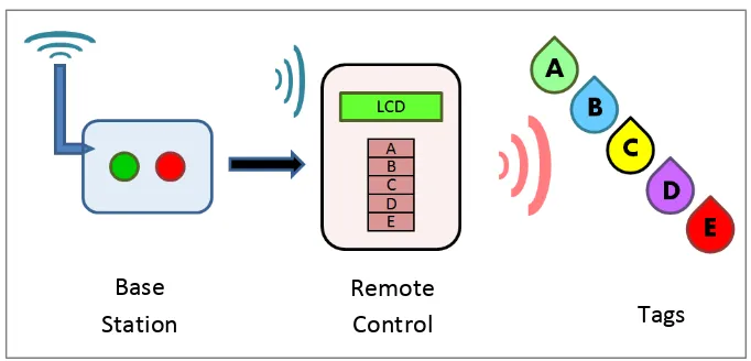
which are the base station, remote control and the tags receiver. Figure 1.1 shows the
3
Figure 1.1: Schematic diagram of the designed product.
The design of the locator system comprised of a base station, remote control
and five tag receivers. Base station will send out a search signal to the remote control,
and the remote control is used to find the tags which are attached to the missing
items. The transmission between the base station and remote control uses ZigBee,
while the transmission between remote control and tags uses RF (radio frequency)
module. The project is designed in this way because RF module is much cheaper to
use for multiple receivers compared to ZigBee. ZigBee features match its price by
having further, more reliable sensing range.
The reason this system consists of three sections is because this structure
offers flexibility for the users to choose whether to fix the remote control in a
specific location, or to make it mobile. This feature will be useful if it happened that
user house is too big for the RF module in the remote controller to sense the tags,
user can then take the remote down from the wall and walk around to search for the
missing item.
How this system works is when a person wishes to find an item which has
been misplaced, they can simply press the button A, B, C, D or E on the remote
control to locate the keys, medicine, wallet or anything that are likely to be
misplaced. A LCD (liquid crystal display) will indicate which button had been
pressed, along with an LED (light emitting diode) which will light up to show that
the search signal has been transmitted. The transmitter will send out the correct
signals to communicate with the corresponding items. The tag on the lost item will
Base
Station
Remote
4
indicate its position by beeping so that it can easily be found. The same concept is
used between the base station and the remote control. If the remote control is being
misplaced, user can press the green button on the base station to locate the remote
control. With an assistive technology like this, it will certainly help in decreasing the
frustrations of Dementia patients and their caregivers.
1.3 Objectives
The objectives of this project are firstly, to design an item locator consisting
of a transmitter and a receiver to locate a misplaced item. The idea is to place the
transmitter in a fixed position where it is easily seen, for example on the wall or on
the door. Then it is used to detect the receiver that might be misplaced within the
range of a house. After this phase of the project is completed, the next objective is to
construct the design by integrating software together with all the required hardware
components. The last objective is to test the functionality of the completed project
within an indoor environment.
1.4 Problem Statement
There are several challenges in this project. Firstly, in terms technical aspect,
the medium of transmission connection between the transmitter and receiver could be
a problem. As the transmitter is going to be fixed on the wall or the door, the search
signal may be out of range from the receiver if the house is too big.
Secondly, the physical size of the remote control and tags post a big
challenge as they have to be of appropriate size to be carried around comfortably. If
the designs are too large, they will not be convenient to carry around, hence lowering
their market value.
Finding a sustainable power source could be a problem. As the remote
controller, which is also the receiver part, has been integrate with many functions,
5 power to sustain the circuit‟s power consumption. And as the remote control is also portable, it is not practical to use heavy bulky battery like lead acid battery.
Lastly, the environment might be a setback if there are a lot of interference
signal in the surrounding, or if the surrounding is too noisy. If the system is placed
near to objects with magnetic field, it might interfere with the communication
between the transmitter and receiver. On the other hand, if surrounding is too noisy,
it might prevent the buzzer from being heard. Also, in terms of physical obstruction,
if any objects are placed on top of the receiver such as pillows or clothes, it could
prevent the buzzer or LED from being heard and seen.
1.5 Scope of Work
This project focuses on assisting people with forgetfulness problem to locate
their frequently misplaced items in the most effective way. The implementation also
includes making it as user friendly as possible, so that Dementia patients will not
have to struggle to remember instructions. It is built to be installed in the house
within the perimeter range of the signal strength between the transmitter and receiver:
the base station and the remote control, or remote control and the tags. Also, the
house must be a place where it is not too noisy until that the buzzer cannot be heard.
The working scope of this project involves three elements, which are explained in
detail in the following subtopic.
1.5.1 Base Station
Base station function is used to find the remote control if ever remote control
gets misplaced. To transmit a search signal from the base station, user has to press
the green button or red button on the keypad. The green button will cause the remote
control to start beeping, while the red button will make the beeping stop. Each time
user presses a button, a LED will light up to acknowledge that the ZigBee transmitter
6
1.5.2 Remote Controller
The remote controller is designed to be flexible. User can fix the remote
controller on the wall, or take it around while searching for lost items. On the remote
control, there is a Zigbee receiver that corresponds with the search signal send from
the base station. The remote will emit a beacon signal, which is audible beeping and
flashing of light. Once the remote is found, user can stop the indicators either from
the base station or the remote control itself.
Also, on the remote control there is a RF transmitter that can detect five
different missing objects whenever user presses an input button on the remote. Each
of the five buttons corresponds to five different tags receiver. And every time the
input button is pressed, a red LED light will indicate the transmitter signal has been
send. At the same time, a LCD will display out which the missing items that have
been attached to the tag.
Other than that, the remote controller can indicate to user when the battery is
weak. It will inform user the amount of percentage left in the battery before it cannot
be used. This is so to warn users to change the battery before it goes completely
empty. This feature is useful as the remote is mobile. If the battery is drained, user
will not be able to use the base station to search for the remote if the remote goes
missing.
1.5.3 Tags Receiver
There are a total of five tags altogether that can be attached to five potential
misplaced items. To find these items, user has to press the button on the remote
control to transmit a search signal. The corresponding tags will „tell‟ users the item‟s
location by beeping for eight seconds, thus enabling users to locate the lost locator
and the attached item. When the receiver‟s battery supply is going to running out, the
buzzer will give out a different tone of continuous buzzing which will not stop until
7
1.6 Project Methodology
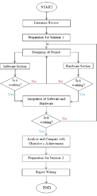
Flow chart in Figure 1.2 is a graphical representation of the project flow to
make the project process clearer. The flow chart is a combination of PSM 1 (Projek
Sarjana Muda 1) and PSM 2 (Projek Sarjana Muda 2). For PSM 1, the requirement
is that students have to suggest their proposal title and do literature reviews, whereby
related work done by others in the past are read and reviewed. At the end of PSM 1,
students supposed to know what their project design is, what components they are
going to use and how they are going to integrate it with software.
For PSM 2, students are required to use their research done in PSM 1 to
design their product out using hardware and software, integrating it together and
testing it whether it is working or not. If it did not work as planned, students have to
go back to designing the project to see what had gone wrong. This process is usually
repeated numerous times as the integration of hardware and software rarely works
out perfectly for the first time. That is why it is advisable to complete the process of
the designing part as quickly as possible because if ever the product does not worked
as intended, there is still time to modify the circuit.
1.6.1 Flow Chart Process Detail
The detail of the flow chart process for is divided into four main sections:
Project Planning, Literature Review, Construction of Prototype and Finalization.
Explanations for each section are described in detail for better understanding.
1.6.1.1Project Planning
First, there must be a problem that have occurred that brought on to the idea
of the proposed project. This is when students know the concept and then look up at
the theories to support the implementation of the project. Then, a flow chart is drawn
8
1.6.1.2Literature Review
Literature review on the past works done by other researchers is considered
the critical points of current knowledge. Typically, the findings are in line with the
particular proposed project, and it helps in contributing theoretical and
methodological facts. It also been used to help students look up for suitable
components to use and what improvement can be made from the existing product.
Other than that, it serves as a background reading to build a stronger base for the students‟ ideas. Literature review is considered as secondary source and can be seen as an abstract accomplishment.
1.6.1.3Construction of Prototype
After researching and knowing which components are available in component
shops, the prototype of project is constructed by integrating both software simulation
and hardware. Once the software simulation is completed, it is integrated into the
hardware. Then the integrated circuit is tested to see whether it is working properly
or not. If it is not, students have to detect the problem, solve it and improve it if
possible, and then test the circuit again to make sure it is working.
1.6.1.4Finalization
Finalization is done after making sure all the components are in working
order, the circuit is working as desired and the system fulfils all the stated objectives.
Once the project has been finalize, it is best not to make any major modification onto
it. Presentation of PSM 2 demonstrates the outcome of the project. After that,
students have to hand in the complete report of their project as stated in the
9