Procedia Engineering 68 ( 2013 ) 245 – 250
1877-7058 © 2013 The Authors. Published by Elsevier Ltd.
Selection and peer-review under responsibility of The Malaysian Tribology Society (MYTRIBOS), Department of Mechanical Engineering, Universiti Malaya, 50603 Kuala Lumpur, Malaysia
doi: 10.1016/j.proeng.2013.12.175
ScienceDirect
* Corresponding author. Tel.+6 06-234-6885 ; fax: +606-234-6884. E-mail address: [email protected]
The Malaysian International Tribology Conference 2013, MITC2013
Comparison of Soot Particle Movement Based on Crank Angle
M.H.M. Hanafi
a*, W.M.F Wan Mahmood
b, Mohd Fadzli Bin Abdollah
a, S.A. Rafeq
a,
N.F.M. Nor
a, Z. M. Zulfattah
a, S.A. Shamsudin
a, A. Ibrahim
aa Center of Advanced Research on Energy, Faculty of Mechanical Enginering, Faculty of Mechanical Engineering, Universiti Teknikal Malaysia
Melaka, 76100 Durian Tunggal, Melaka, Malaysia
bFaculty of Engineering and Built Environment, Universiti Kebangsaan Malaysia, 46300 UKM Bangi, Selangor, Malaysia
Abstract
In a diesel engine, soot was produced due to incomplete fuel combustion in a combustion chamber. Some of this soot sticks to the cylinder wall and interferes with lubricant oil. This soot causes the lubricant oil to contaminate and this increases its viscosity. Contamination of lubricant oil is one of the major causes of engine wear. Therefore, the focus of this study is on soot movement in diesel engine that is the initial step to avoid contamination of lubricant oil. This work uses the data of the formation of soot particles from Kiva-3v obtained from previous investigation and then simulated it by a Matlab routine. Kiva-3v produced velocity vectors of the soot, fuel, temperature, pressure and others. Matlab routine uses trilinear interpolation and fourth order Runge Kutta method in order to calculate soot movement in a combustion chamber. In addition, the influence of drag force is considered in the calculation to achieve a higher accuracy. The objective of this study is to compare soot particle movement between 8° ATDC and 18° ATDC. Results show that 8° ATDC has a high risk to contaminate lubrication oil in certain location compare to 18° ATDC.
© 2013 The Authors. Published by Elsevier Ltd.
Selection and peer-review under responsibility of The Malaysian Tribology Society (MYTRIBOS), Department of Mechanical Engineering, Universiti Malaya, 50603 Kuala Lumpur, Malaysia.
Keywords: After Top Dead Center (ATDC), Soot, Kiva -3v, Drag force; (Direct Injection) DI Diesel engine and lubricant oil
Nomenclature
ܨௗ drag force ȡ density of fluid
ݒ velocity of the object relative to the fluid A cross sectional area
ܥௗ drag coefficient
rho radial direction of x axis
ș angular
z axial direction of z axis
© 2013 The Authors. Published by Elsevier Ltd.
Introduction
For some years, an outbreak of activities related to the fossil fuel is significant in some sectors especially transportation. However, fossil fuel is very limited on the earth and it is beginning to diminish. As a result, it may not be possible to provide the amount of energy demanded by the world in the future. Nevertheless, world fossil fuel consumption has been increasing due to the world energy demand. Diesel engine is one example of using fossil fuel (diesel) to run its operation. It has been extensively and widely used as an alternative power source due to some characteristics such as energy efficiency, durability, packaging efficiency and fuel safety [1]. In fact, diesel engine is an internal combustion engine which uses the heat of compression to initiate ignition to burn the fuel that has been injected into the combustion chamber. Despite these advantages, the diesel engine produces a lot of gas emissions such as soot, nitrogen oxides (NOx), sulfur oxides (SOx) and noise emissions [2]. Soot which causes contamination of lubrication oil is one of the major influences of increased in engine wears [3]. The wear mechanism due to the soot is still not fully understood. Hence a fundamental study in this area is needed.
Generally, internal combustion of engine produces soot due to incomplete fuel combustion. The methods used to injected and ignited fuel are among the causes of soot formation. In diesel engines, fuel is injected during the compression stroke and ignited spontaneously from the compression pressure [4]. Bonatesta et al. [5] investigated on soot distribution in a diesel engine by using CFD software, Kiva-3v. Kiva-3v is a reliable software to simulate the soot formation in a diesel engine combustion chamber [5]. The software implements a two stage of Hiroyasu soot model in the simulation. The two stage soot models are for soot formation and soot oxidation [6]. Soot particle size prediction along its path by using combination of Hiroyasu’s soot formation and Nagle and Strickland-Constable soot oxidation rate expression as discussed in [7]. However this study, did not take wall deposition mechanisms such as electrophoresis, inertial deposition, gravitational sedimentation and thermophoresis into consideration. According to [8], in order to identify and understand soot formation, wall deposition mechanisms are important to be explored. The studies by Hong et al. [9] carried out a model for soot formation process in diesel engine but the result of the model was different from the experimental result. Besides that Christopher et al. [10] also carried out a simplified model for soot formation by using CFD simulation. Mancaruso et al [11] carried out an experimental method to analyze combustion process in transparent engine. By this method, soot concentration can be investigated and identified clearly. The objective of this study is to analyze soot movement at 8° ATDC and 18° ATDC in a cylinder of a diesel engine and to predict the possibility of soot particles to stick to the wall of the cylinders.
Kiva-3v, and Engine specification
Kiva-3v was used in previous investigation to obtain data of in-cylinder soot formation. The data obtained from the Kiva-3v simulation included velocity vectors of the soot, fuel, temperature and pressure [7]. It employed a two step model: Hiroyasu’s soot formation [12] and Nagle and Strickland-Constable soot oxidation [13] rate expressions. The engine has a bowl-in-piston and flat cylinder head face configuration, with a seven-hole injector installed vertically and centrally.
Table 1 Specifications of the Engine
Parameters Specifications Engine Type 4 valve DI diesel Bore × Stroke 86.0 × 86.0 mm Squish height 1.297140330 mm Compression Ratio 18.2:1
Displacement 500 cm3
Piston Geometry Bowl-in-piston
Table 2 Specifications of the mesh configuration
Parameters Mesh configuration Total number of cells 201,900
Number of cells
Azimuthal 150 Radial 37 (20 in bowl region) Axial 39 (15 in bowl region)
Resolution
Azimuthal ( °) 2.4°
Radial (mm) 0.83 – 1.15 Axial (mm) 0.99 – 3.63
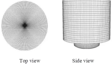
Fig. 1 shows the top and side view of the mesh configuration of the piston. The data from experimental result by [7] was used for the simulation and model validation.
Fig. 1. Mesh configuration of piston bowl-in.
Soot Particle Tracking
By using MATLAB, the data for soot concentration that was used by [7] was employed to investigate the soot movement in the combustion chamber. The mathematical algorithm used in the MATLAB routine are trilinear interpolation and fourtth order Runge-Kutta. In this study, the drag force equation is included in the simulation to determine soot movement. The drag force equation is:
To analyze the movement of the soot particles, it is necessary to identify the initial position of the soot particle. This can be found based on the zone of soot distribution with certain crank angle ATDC [6]. After selecting the crank angle and zone, the starting coordinate in radial (rho), angular (ș) and axial direction (z) were also decided. Soot particle movement paths have been studied by considering reasonable crank angle. In this paper the reasonable crank angles investigated are at 8° ATDC and 18° ATDC. The 8° ATDC is the intermediate of fuel injection which contains soot particle moves towards the bowl wall. While 18° ATDC is the point where fuel injection is already completed in the combustion chamber and soot formation process is dominating. Comparisons of the soot particle based on these angles were carried out from the results of the simulation.
Results and Discussion
8° ATDC 18° ATDC
Fig. 2. Radial sensitivity: rho= 1.5 cm-2.2 cm, ș =25° and z=8.8 cm.
The data collected from this study were based on two crank angles: 8° ATDC and 18° ATDC. By considering rho sensitivity, where rho=1.5cm-2.2cm, ș =25° and z=8.8cm, both of the results were obtained as shown in Fig 2. The results of the 8° ATDC showed that when rho is 1.5cm, soot particle movement went closer to the cylinder wall. Soot particle that are closer and stick to the cylinder wall has a high potential to contaminate lubrication oil. Other soot particle movements do not have the tendency to get closer to the cylinder wall. Result by 18° ATDC also demonstrates a lower tendency for soot particle movement as 8° ATDC.
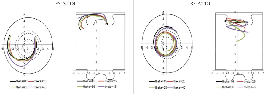
8° ATDC 18° ATDC
By considering angular sensitivity, the results of the 8° ATDC and 18° ATDC combustion setting showed that their soot particle movements were totally different as illustrated in Fig 3. Soot particles formed during the 8° ATDC have a high possibility to go near the cylinder wall. The result based on 18° ATDC shows that soot particle moves to middle area of the cylinder wall. This can avoid the soot particle from mixing with the lubrication oil.
8° ATDC 18° ATDC
Fig. 4. Radial sensitivity: rho= 1.8 cm, ș =25° and z=8.5-9.1 cm.
Analysis of the soot particle movement by considering the sensitivity of radial were also carried out as shown in Fig 4. The result showed is almost similar to Fig 3. Almost all of the soot particles move downwards in a counter clockwise motion. Besides, the result indicated that soot particles have a higher risk to approach the wall for the 8° ATDC setting compared to 18° ATDC.
Conclusion
The study shows that at 8° ATDC combustion configuration has a high potential to contaminate lubrication oil in certain locations. Nevertheless further investigation in term of wall deposition mechanism and soot particle size is needed. In addition the overall result shows that during 18° ATDC, soot particle does not moves closer to the cylinder wall, hence it will not affect and contaminate the lubrication oil. As a result, this potentially increases the performance and efficiency of diesel engine.
Acknowledgement
The authors would like to acknowledge the funding from Universiti Teknikal Malaysia Melaka (UTeM) PJP/2012/FKM(8A)/S01082 and Universiti Kebangsaan Malaysia. Greatest thanks to ALLAH and a special thanks to all colleagues involved in this study.
References
[1] R. Charles. Diesel Technology and American Economy.D02378-00 Report, Diesel Technology Forum, One Dulles Tech Center, October 2010.
[2] A.N. Shah., G.Y. Shan,., T.J-Wei,., Carbonyls emission comparison of a turbocharged diesel engine fuelled with diesel, biodiesel, and biodieselediesel blend, Jordan Journal of Mechanical and Industrial Engineering 3 (2) (2009) 111e118.
[3] S. George., S. Balla, M. Gautam, Effect of diesel soot contaminated oil on engine wear, Wear 262 (2007) 1113–1122.
Engine, Third European Combustion Meeting ECM 2007.
[6] K. Boussouara and M. Kadja, Numerical investigation of soot formation in diesel jet flame with KIVA-3V, Revue des Energies Renouvelables Vol. 12 N°1 (2009) 55 – 62.
[7] W. M. F. W. Mahmood, 2011. Computational Studies of Soot Paths to Cylinder Wall Layers of a Direct Injection Diesel Engine. PhD Thesis Department of Mechanical, Materials and Manufacturing Engineering 2011, The University of Nottingham. [6] Francisco J. Collado, Preliminary design of surrounding heliostat fields, Renewable Energy 34 (2009) 1359-1363..
[8] B.R. Suhre and D.E. Foster, In-cylinder soot deposition rates due to thermophoresis in a direct injection diesel engine. SAE Papers, 1992(921629).
[9] S. Hong,, M.S. Wooldridge, H.G. Im, D.N. Assanis, and H. Pitsch, Development and application of a comprehensive soot model for 3D CFD reacting flow studies in a diesel engine. Combustion and Flame, 2005. 143: p. 11-26.
[10] W. Christopher, L. John and D.R, Nicholas. A simplified model for soot formation and oxidation in CFD simulation of non-premixed hydrocarbon flames. Fire Safety Journal 40 (2005) 141–176.
[11] E. Mancaruso, L. Sequino, and B.M. Vaglieco. GTL and RME Combustion Analysis in a Transparent CI Engine by means of IR Digital Imaging.Proceedings of ecos 2012 - the 25th international conference onefficiency, cost, optimization, simulation and environmental impact of energy systems june 26-29, 2012, perugia, Italy.
[12] H. Hiroyasu,., and K. Nishida,., Simplified Three-dimensional Modeling of Mixture Formation and Combustion in a D.I. Diesel Engine. SAE Papers, 1989(890269).