Smart Classroom Using LabVIEW
DE CHEE KEONG
This report is submitted in partial fulfillment of the requirements for award of Bachelor of Electronic Engineering (Industrial Electronics) With Honours
Faculty of Electronic and Computer Engineering Universiti Teknikal Malaysia Melaka
ii
UNIVERSTI TEKNIKAL MALAYSIA MELAKA
FAKULTI KEJURUTERAAN ELEKTRONIK DAN KEJURUTERAAN KOMPUTER
BORANG PENGESAHAN STATUS LAPORAN
PROJEK SARJANA MUDA II
Tajuk Projek : Smart Classroom Using LabVIEW
Sesi
Pengajian : 1 0 / 1 1
Saya DE CHEE KEONG mengaku membenarkan Laporan Projek Sarjana Muda ini disimpan di Perpustakaan dengan syarat-syarat kegunaan seperti berikut:
1. Laporan adalah hakmilik Universiti Teknikal Malaysia Melaka.
2. Perpustakaan dibenarkan membuat salinan untuk tujuan pengajian sahaja.
3. Perpustakaan dibenarkan membuat salinan laporan ini sebagai bahan pertukaran antara institusi pengajian tinggi.
4. Sila tandakan ( √ ) : 5.
SULIT*
*(Mengandungi maklumat yang berdarjah keselamatan atau kepentingan Malaysia seperti yang termaktub di dalam AKTA RAHSIA RASMI 1972)
TERHAD** **(Mengandungi maklumat terhad yang telah ditentukan oleh organisasi/badan di mana penyelidikan dijalankan)
TIDAK TERHAD
Disahkan oleh:
__________________________ ___________________________________
(TANDATANGAN PENULIS) (COP DAN TANDATANGAN
PENYELIA)
Tarikh: Tarikh:
iii
―I hereby declare that this report is the result of my own work except for quotes as cited in the references.‖
Signature :
Author : DE CHEE KEONG
iv
―I hereby declare that I have read this report and in my opinion this report is sufficient in terms of the scope and quality for the award of bachelor of Electronic Engineering
(Industrial Electronics) With Honours.‖
Signature :
Supervisor‘s Name : MDM. YUSMARNITA BINTI YUSOP
v
vi
ACKNOWLEDGEMENT
For the first of most, I feel thankful for the blessing of God. ―He‖ gave me the strength to carry on my final year project to the completion.
I would like to sincerely thank my supervisor, Mdm. Yusmarnita Binti Yusop, who provided me with guidance and encouragement throughout the pursuit of this degree. Because of her encouragement, support and patience during this project give me a big strength to fulfill the final year project. I very appreciate her guidance and encouragement. If not, I can‘t success to fulfill the tasks of final year project.
Besides that, I want to say thousands of thank you to all my friends that help me and giving opinion along the implementation of the project.
vii
ABSTRACT
viii
ABSTRAK
ix
TABLE OF CONTENTS
CHAPTER TITLE PAGE
PROJECT TITLE i
BORANG PENGESAHAN STATUS LAPORAN ii
STUDENT DECLARATION iii
SUPERVISORY DECLARATION iv
DEDICATION v
ACKNOWLEDGEMENT vi
ABSTRACT vii
ABSTRAK viii
TABLE OF CONTENTS ix
LIST OF TABLES xiii
LIST OF FIGURES xiii
LIST OF ABBREVIATION xv
LIST OF APPENDIX xvi
I INTRODUCTION
1.1 Background 1
1.2 Objective 3
1.3 Problem Statement 3
1.4 Scopes of Work 4
1.5 Project Significant 4
x
1.7 Report Structure 5
II LITERATURE REVIEW
2.1 Introduction 7
2.2 LabVIEW 8
2.2.1 LabVIEW Programming 8
2.2.2 Dataflow Programming 9
2.2.3 Graphical Programming 10
2.2.4 Advantages Of Using LabVIEW 11
2.3 Data Acquisition (DAQ) 12
2.3.1 NI DAQ USB 6009 13
2.3.2 Advantages of Using NI USB-6009 14
2.4 SMS 14
2.4.1 Benefits of SMS 16
2.5 Sensor 17
2.5.1 Comparison between Sensors 18
2.5.1.1 RFID 18
2.5.1.2 Pressure Sensor 19
2.5.1.3 Passive Infrared Sensor (PIR) 20
2.5.1.4 Infrared Sensor 21
2.5.1.4.1 Object Detection using IR Light 22 2.5.1.4.2 Advantage of using IR Sensor 23
2.6 GSM Modem 24
2.7 AT Commands Interface 25
2.7.1 Basic Commands and Extended Commands 26
2.8 Relay Operation 27
2.9 Rectifier 28
xi
2.9.3 Full-Wave Bridge Rectifier 31 2.10 Light-emitting diode (LED) 32
2.10.1 Physics of LED 34
2.10.2 LED Lamp 35
2.10.3 High Brightness LED 36
III PROJECT METHODOLOGY
3.1 Introduction 38
3.2 Flow Chart Diagram 39
3.3 System Block Diagram 41
3.3.1 Hardware Part Development 41 3.3.2 Software Part Development 42 3.3.2.1 Software Design Flow 43
3.3.2.1 Front Panel 44
3.3.2.2 Block Diagram 45
3.3.2.3 Control and Indicators 46
3.3.2.4 Control 46
3.3.3 Schematic for Circuit Design 47
IV RESULT AND DISCUSSION
4.1 Introduction 50
4.2 Analysis of Overall System 50
4.3 Software Analysis 51
4.3.1 Analysis of Front Panel 51
4.4 Analysis of Energy Saving 53
xii
V CONCLUSION AND RECOMMENDATION
5.1 Conclusion 59
5.2 Recommendation 60
xiii
LIST OF TABLES
NO TITLE PAGE
2.1 Approximate Power Saving With IR Sensor 23 4.1 Comparison between the before and after the Smart Switching
System is applied 53
LIST OF FIGURE
NO TITLE PAGE
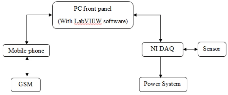
1.1 System Block Diagram 2
2.1 A While Loop in G is intuitively represented by a graphical loop, which executes until a stop condition is met 10
2.2 NI DAQ USB 6008/6009 13
2.3 RFID (Radio-frequency identification) 18
2.4 Pressure Sensor 19
2.5 Passive Infrared Sensor (PIR) 20
2.6 Infrared Sensor 21
2.7 Basic Operation of IR Sensor 23
2.8 GSM Modem 24
2.9 Relay 27
2.10 Half-wave Rectifier 30
xiv
2.12 Bridge Rectifier 31
2.13 LED Schematic 34
2.14 HB LED 37
3.1 Methodology Flow Charts 39
3.2 System Block Diagram 41
3.3 Software Design Flowcharts 43
3.4 Window of Front Panel 44
3.5 Window of Block Diagram 45
3.6 Basic Controls 47
3.7 Schedule Mode Circuit Diagram 48
3.8 Schematic Diagram of Infrared Sensor and Comparator 48 3.9 Schematic of the Sensor Mode operation 49
4.1 Front Panel of Smart Switching System (Schedule) 51 4.2 Front Panel of Smart Switching System (Sensor) 52
4.3 (a) System switching circuit & (b) 240V switching circuit. 54
4.4 Comparator with IR sensor 54
xv
LIST OF ABBREVIATION
LabVIEW - Laboratory Virtual Instrumentation Engineering Workbench
xvi
LIST OF APPENDIX
NO TITLE PAGE
A DAQ Datasheet 62
B Analysis of Block Diagram 68
CHAPTER 1
INTRODUCTION
This chapter will give reader a basic introduction of how the idea of the project generated. In this chapter will show the introduction, objectives, problems statement, scopes of work, methodology, and simple brief for the report structure.
1.1 Background
From the previous project, we can know that there are no people (student or lecturer) who concern to switch off supply after the lecture session was finished. The supply always be forgotten to be switch off while there have no student in the classroom. The supply will always turned off by the BPA staff in the evening. This smart switching system will used to control the power supply by using sensor or follow the preset time
schedule in order to reduce energy waste.
2
energy and money. Besides that, when the lecturer wants to use the lecture room need to arrange the time table switch on the power system.
The new Smart Classroom Using LabVIEW is easier to use. By using a sensor and LabVIEW software, we can switch the power system by using SMS or sensor. When sensor detect there has a person, the power system will switch on and it will turn off when the sensor sense no body at there. Besides that we can also switch on and off the power system by using SMS.
This project presents the design of a smart switching system for classroom advanced with using sensor for the object detection. First of all, the LabVIEW software is used to create a front panel of virtual instrument. The front panel will let user to choose whether they want to use sensor or schedule mode. When schedule mode had been choose, the system will read the time and switch the power supply follow the schedule. When the sensor mode had been choosing, the sensor will start to read the appearance of students and lecturers, if it detect appearance, it will send signal to DAQ and switch the power supply, else it will remain off.
[image:18.612.151.535.517.678.2]Finally, the Smart Classroom Using LabVIEW project will let us have more convenient and save our energy, money and of course our environment.
3
1.2 Objectives
The main objective of this project is to upgrade the smart switching system and by adding a sensor circuit in to it. Hence there have many objectives that need to be achieving for this project.
i. To design an alternative control by using SMS application to communicate the PC thus the power loads can be turn on or off manually.
ii. To design the hardware as interface between software and hardware by using GSM modem, NI DAQ, and others electronic components.
iii. To study and understand the basic concepts of the LabVIEW software.
iv. To monitor the status of power loads through the front panel and provided SMS notification with any system operation failure.
v. To save the usage of electricity by through efficiency control system and low power dissipation load.
vi. To design a sensor switching system provide automatic switch on/off via PC.
1.3 Problem Statement
4
1.4 Scopes Of Work
This project covered few parts, which are:
i. Study of LabVIEW software programming language.
ii. Study and understand the LabVIEW block diagram of previous project.
iii. The study of NI DAQ 6009 which used for interfacing between hardware and software.
iv. The Prototype development to perform the system operation.
All the scopes above function in a system to control the power system.
1.5 Project Significant
There have few problems that we will face during the development of this project:
i. Overcome the problem of interfacing between LabVIEW software and GSM modem.
ii. Redesign the program of previous project and include the sensor circuit into it. iii. Will be able to shut on and off the supply by sensor detecting.
iv. Interfacing between the sensor with the DAQ device.
1.6 Project Methodology
5
sensor and DAQ. Second part is software design such as LabVIEW front panel and block diagram design. For literature review stage, the research had been done on the sensors comparison, comparison between the Programming, designing the sensor circuit, research on senior‘s project and so on. For hardware part, construct the sensor circuit and interfacing the sensor with the DAQ, study how to solve over current and system overall testing. If the output meets the requirement and specifications, the project can consider as success. If the output did not fulfill the requirement and specifications, so troubleshooting and seeking information is need for redesign the overall project. For more details, will be explained and discussed in project methodology which is Chapter III.
1.7 Report Structure
This report is documentary delivering the ideas generated, concepts applied, activities done, and finally the product of project itself. It consists of five chapters. Following is a chapter-by-chapter description of information in this report.
Chapter I : Introduction
This first chapter is more on the general overview of the project. In this chapter, the background of the problem and the emergence of the project are stated first. Besides, the project objectives, scope of project and the methods used are also included.
Chapter II : Literature Review
6
Chapter III : Project Methodology
In project methodology, the materials, subjects, and equipment or apparatus used are identified. Besides, the methods or procedures during the project implementation are also stated. Insufficient, the justification for choosing the method or approach is also stated.
Chapter IV : Results and Discussion
In this chapter, the observation and result obtained from the data analysis are presented. Then, the project discovery is arranged tidily using the aid of figures and tables. Besides, the result or discovery is explained and compared with previous studies. Then, the result from the comparison is discussed.
References & Appendices
CHAPTER II
LITERATURE REVIEW
This chapter will discuss about the literature discourse and the review of smart switching system. This chapter is regarding the background study of the project to perform and documented about the theoretical concept applied in completing the project. It included SMS, LabVIEW, DAQ and so on. Then is the reason of choosing the specific software and hardware.
2.1 Introduction
Nowadays, the world looks to sensors to play a bigger role in the control systems. Sensors are already an accepted platform for system supervisory control. The well-function of the sensor and the easy-to-use for switching system make it work more efficiency. In this project, sensor circuit and National Instrument LabVIEW software is implemented to reduce the waste of energy and provide more effective management system in FKEKK.
8
circuits, advantages of the LabVIEW software, Infrared Sensor, the energy saving by the sensor and so on. The study is needed for solving the problems that‘s we face to.
2.2 LabVIEW
LabVIEW (short for Laboratory Virtual Instrumentation Engineering Workbench) is a platform and development environment for a visual programming language from National Instruments. The purpose of such programming is automating the usage of processing and measuring equipment in any laboratory setup. The graphical language is named "G" (not to be confused with G-code). Originally released for the Apple Macintosh in 1986, LabVIEW is commonly used for data acquisition, instrument control, and industrial automation on a variety of platforms including Microsoft Windows, various versions of UNIX, Linux, and Mac OS X.
2.2.1 LabVIEW Programming
In this project, LabVIEW has been used as the main platform. LabVIEW is a modern graphical programming language that has been widely adopted throughout industry, academia, and government lab as the standard for data acquisition, instrument control software, and analysis software [1]. LabVIEW is not a panacea; for simple tasks it is unsurpassed, but, like any programming language, programming complicated applications is difficult. While LabVIEW does not resemble other languages, many of the programming guidelines you may have learned previously still apply: breaking functionality down into subroutines, testing subroutines individually, avoiding side effects like global variables, paying attention to memory management, and using efficient data structures are always worthwhile.