ISSN 1818-4952
© IDOSI Publications, 2013
DOI: 10.5829/idosi.wasj.2013.21.8.2126
Corresponding Author: Chee Fai Tan, Integrated Design Research Group (IDeA), Faculty of Mechanical Engineering, Universiti Teknikal Malaysia Melaka, Melaka, Malaysia.
Design of a Feature Recognition System for CAD/CAM Integration
Chee Fai Tan, V.K. Kher and N. Ismail
1 1 2
Integrated Design Research Group (IDeA), Faculty of Mechanical Engineering,
1
Universiti Teknikal Malaysia Melaka, Melaka, Malaysia Faculty of Engineering, Universiti Putra Malaysia, Selangor, Malaysia
2
Abstract: This paper presents a methodology for implementing the feature recognition system for achieving the Computer Aided Design/ Computer Aided Manufacturing (CAD/CAM) integration goals. The Feature-based modeling is being used to model the solid models. The features being considered in this paper is hole form feature. The input of the feature recognition system is the Standard for the Exchange of Product Model Data (STEP) files. The set of feature recognition rules is generated by using ruled based technique.
Key words: CAD/CAM Form feature STEP Feature-based modeling Feature recognition
INTRODUCTION applications is based on the possibility to associate During the past 10 years, research on CAD/ CAM Product and process information can be retrieved from the integration had focused on product representation feature-based model to support manufacturing tasks such techniques or product modeling that contains more as process planning, assembly planning and fixture complete product information and providing better design [1].
interfacing opportunities between CAD and CAM Data exchange and system integration have become systems. One of the most popular modeling approaches important consideration in computer-aided systems in for manufacturing activities involves the use of feature order to improve productivity. This had led to the based models [1]. The commercial CAD/CAM marketplace development of neutral format that is used to facilitate is still very much in its infancy, with many vendors product data exchange between manufacturing fulfilling limited niches, each with their own particular components. In the early 1980s, National Institute of suite of integrated software modules and data structures. Standards and Technology (NIST) have adopted STEP A de facto CAD/CAM integration scheme has yet to to represent product data throughout its life-cycle. emerge [2]. For the CAD/CAM integration, the basic The standard is an extension of previously defined parts are the feature and feature-based representation. standards such as IGES, VDAF and DXF. STEP provides In general, the feature can be viewed as higher level a wider coverage of product model to encompass several entities that integrate the information between design and computer-aided applications and as a basis towards fully manufacturing. For example, the topological and integrated system [3]. There are two main approaches that geometrical information consists in CAD, feature can be have been developed in conjunction with feature based used to represent how the part can be manufactured. models [4]:
Feature based modeling is viewed from the
manufacturing viewpoint as more suitable for modeling Design-by-features in which the designer create the because it deals with shape attributes related to part directly as a combinations of standard features; manufacturing. With feature based models, shape and
information and other information (such as functional and Feature recognition which involves computationally non-geometrical information) can be stored. The potential recognizing features from conventional geometrical of feature based CAD in supporting manufacturing models.
Block Cylinder
Hole
Boss
Through slot The feature recognition approach is to extract the
information that are needed from the CAD database. Feature recognition is a step to reduce the lead time between design and manufacturing. Abdalla [5] had proposed a technique that has the capability to extract required feature directly from the database of a CAD solid
modeling system. The technique has the capability to (a) Design features extract the necessary topological and geometrical
information from the solid modeler. There are many approaches that have been proposed to recognize and extract the feature from B-rep solid models, which are Artificial Intelligent (AI), Graph-based, Syntactic Pattern recognition and Neural Network (NN) [4].
This paper focuses on feature recognition of form feature from 3D CAD models such as hole by using STEP file. The UniGraphics (UG) CAD system had been adopted in this paper for the feature-based modeling environment
and generation of STEP files. The STEP files that consist (b) Manufacturing features of geometrical information will used in feature recognition
system. The feature recognition rules are generated by Fig. 1: Design Features and Manufacturing Features [6] using ruled based technique.
Form Feature and Feature: A feature is an entity or region of a closed oriented surface bounded by one geometric form. Its attributes (dimensions, shape, etc.) or more edge loops.
are very important for various industrial functions, such
as analysis, evaluation and process planning. The feature For B-rep models, it was found out that the more attributes must be represented explicitly in terms of forms useful data are the topological and the geometrical that match available manufacturing knowledge. Example information. The topology data describes the of form features are holes, slots, cuts, rounds and notches connectedness between the components while geometry
[5]. specifies the dimensions and location of each component
Recently, there are two classifications of features, [6]. which are manufacturing features and design features.
The manufacturing features used by production planning Feature-Based Modeling: Recently research towards engineers in manufacturing process planning, whereas the CAD/CAM integration has concentrated on feature-based design features is the features that defined by design models to design the part model. Part description in engineers at the design stage [11-13]. Fig. 1 shows the current CAD model is in the form of basic geometry differences between the two features. Feature contains (faces, lines, points) and topology that is unsuitable for manufacturing oriented information where it is the basis direct application in manufacturing process such as for integration between CAD/CAM [6]. The feature process planning. This problem can be overcome by representation in this paper is using boundary defining a part in terms of high level geometric entities representation (b-rep). According to Ismail [1], the like holes, steps and slots,. which are called features [7]. elements of the B-rep data structure has the following The feature-based modelings for this paper is under the
characteristics: UG CAD system. The form features are modeled using
A vertex (vi) is a unique point in x, y, z coordinates. A system, the designer has to create a base feature and add vertex is typically shared by three faces or surfaces). the features by subtracting them from the base feature. An edge (ei) is a finite, a non self-intersecting, The form features being considered in this paper are directed space curve bounded by two vertices. holes. According to Salomons [8], from a design point of A set of connected edges that form the close view, feature based modeling has much better potential boundary of a non-self-intersecting face is known as for computer support of the design process than current a loop or also referred to as an edge loop. non-feature-based CAD system. Features able to help the A face is a finite connected, non-self-intersecting
Model part using design-by-features approach
Convert to STEP file
Extracting geometrical data from STEP files
Development of feature recognition system
Form Feature
Hole
Through Blind
designer to speed up their design process based on standardization. The feature is able to reduce the design cost, shorter time to market, better design quality as well as able to integrate different applications such as process planning and analysis.
System Implementation: The solid model will produce a STEP file using Unigraphics postprocessor. The STEP file contains the geometrical data of the solid model. The information in the STEP file maintains the structure and dimensions of the solid model and B-rep information of the solid. The STEP representation format can be used in different CAD system.
The feature recognition system in this paper is Fig. 2: The methodology for feature recognition implemented in three modules which are as follows.
Module 1 - generate the STEP file. The UG STEP generation tools being used to translate the part to standard STEP representation and store as STEP file. Module 2 – interrogate and extract the geometric information of STEP file. The data is then processed and input to the feature recognition system.
Module 3 – feature recognition using geometrical and rule-based technique.
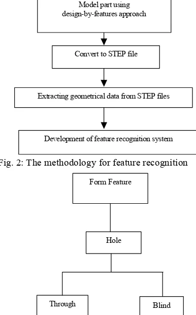
Fig. 2 Shows the methodology for feature recognition
in this paper. Fig. 3: Taxonomy of features (Hole)
In this paper, the hole has been proposed to use in
feature recognition system. The taxonomy of a hole is RESULT AND DISCUSSIONS shown in Fig. 3. The STEP file contains the entities such
as circles, lines, planes and text. Every entity has The B-rep is a explicit feature representation. A associated with various attributes like color and linetype. B-rep solid model is constructed using entities like line To take an example, the line entity in STEP may look (or edges), faces and points (or vertices). Fig. 4 and
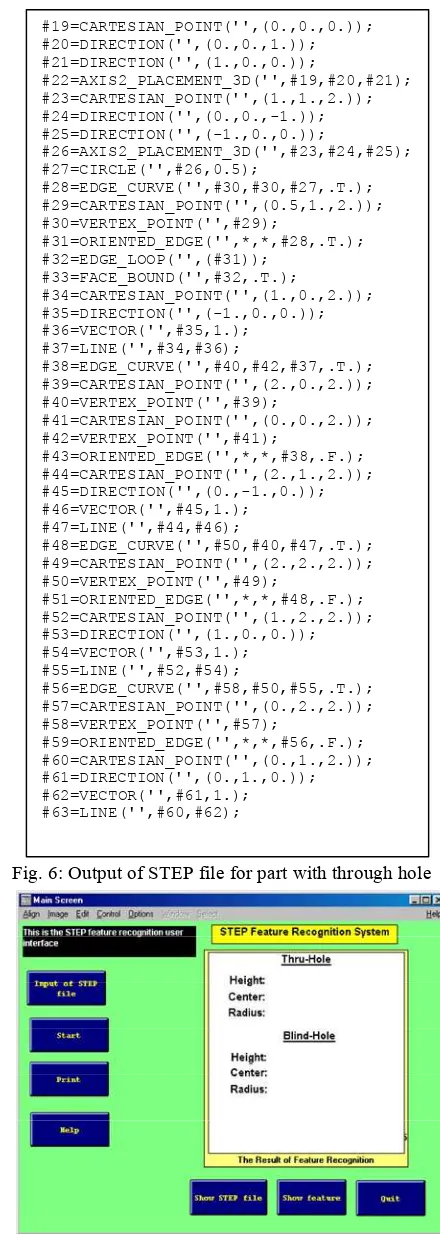
as follows: Fig. 5 shows the examples of B-rep model of through and
#37= LINE(‘’,#34,#36); the entity type The B-rep models are converted to STEP #39=CARTESIAN_POINT(‘’,(2.,0.,2.)); the first point representation format through UG postprocessor [10]. #41=CARTESIAN_POINT(‘’,(0.,0.,2.)); the second point The output of the 3D model for Figure 4 in the STEP #35=DIRECTION(‘’,(-1.,0.,0.)); the extrusion direction representation format is shown in Fig. 6.
The rule-based approach uses AI technique to paper. The type of a form feature can be recognized by develop a set of rules. According to Ismail [9], the using the following approach:
algorithms identify a feature based on certain
pre-specified rules that are characteristic to the feature. IF [A] THEN [B] The following set of heuristic rules is used to describe a
through hole feature [9]: where A are the condition and B are the results. The IF circular edges are found and recognize the through hole and blind hole. The Point incir_edge1 and cir_edge2 is 1 recognition of through hole was proposed through the
THEN identify through hole following rule:
blind hole which is proposed to be recognize in this paper.
The rules for feature recognition are proposed in this
#19=CARTESIAN_POINT('',(0.,0.,0.));
Fig. 4: B-rep model of a part with through hole
Fig. 5: B-rep model of a part with blind hole IF
Total circle number = 2 & Total cylindrical number = 1 & Face type = cylindrical_surface &
The two circle are subtract from the adjacent plane The two circle are adjacent to cylindrical_surface THEN
Feature type = hole (through)
The blind hole was recognized through the following proposed rule:
IF
Total circle number = 2 &
Face type of one circle = plane & Fig. 7: The User interface main menu
Total cylindrical number = 1 & 3. Shaharoun, A.M. and J.A. Razak, 1999. STEP-Based Face type = cylindrical_surface & Central Repository for Product Data Sharing Among One circle is subtract from the adjacent plane Computer-Aided Systems in Manufacturing One circle is adjacent and perpendicular to cylincrical - Applications. Proceeding of Worlds Engineering
surface Congress 1999- Towards the Engineering Vision:
THEN 4. Shah, J.J. and M. Mantyla, 1995. Parametric and
Feature type = hole (blind) Feature-Based CAD/CAM. John Wiley and Sons,
Inc. Tseng.
The proposed rules for through hole and blind hole 5. Abdalla, H.S. and J. Knight, 1994. An Expert System will input to the feature recognition system. The rules will for Concurrent Product and Process Design of use to define the STEP file accordingly. The user interface Mechanical Parts. Proceeding Institution Mechanical for feature recognition system also being developed in Engineers, 208: 167-172.
this paper. Fig. 7 show the user interface and the 6. Ismail, N., C.F. Tan and S.M. Sapuan, 2000. Form parameter selection menu respectively. Feature for Concurrent Engineering. 2000 TENCON
CONCLUSION for the New Millennium, 3: 468-471.
A prototype feature recognition system has been Features from B-rep Solid Models. ASEAN Journal of proposed to support the CAD/CAM integration. Science and Technology Development, 14(2): 35-49. Currently the form features recognized through holes 8. Salomons, O.W., 1995. Computer Support in the and blind holes. The part is modeled using the design-by- Design of Mechanical Products. Ph.D Thesis, features approach of the UG CAD system module. Then University of Twente.
geometric description of part is presented in STEP neutral 9. Ismail, N. and N. Abu Bakar, 1997. Recognition of data format. For the purpose of feature recognition Machined Features from Solid Database of Prismatic process, the STEP format must be sorted first. The Components. Pertanika Journal of Science and rule-based technique had been proposed for this paper Technology, 5(2): 231-240.
in order to extract the features data. The user interface 10. Unigraphics User Menual Version 13, 1997 also being proposed for the feature recognition system. (Electronic Data System Corporation, Unigraphics For future research, the recognition of complex hole Division, MO USA).
features and other features such as slots, pockets, 11. Sunil, V.B. and S.S. Pande, 2008. Automatic bosses, step and ribs can be developed. Recognition of Features from Freeform Surface CAD REFERENCES 12. Ran, J.Q. and M.W. Fu, 2010. Design of Internal Pins 1. Ismail, N., N. Abu Bakar, M.R. Osman and Recognition of Undercut Features. Computer-Aided
S.M. Sapuan, 1999. Feature Recognition Approach Design, 42(7): 582-597.
for Computer Aided Manufacturing. Proceeding of 13. De Martino, T., B. Falcidieno and F. Giannini, 1994. Worlds Engineering Congress 1999- towards the An Adaptive Feature Recognition Process for Engineering Vision: Global Challenges and Issues, Machining Contexts. Advances in Engineering
pp: 325-329. Software, 20(2-3): 91-105.
2. Regli, W., 1995. Geometric Algorithms for Recognition of Feature from Solid Models. Ph.D thesis, University of Maryland.
Global Challenges and Issues, pp: 215-219.
Proceedings: Intelligent Systems and Technologies 7. Ismail, N. and A.N. Bakar, 1997. Recognition of
![Fig. 1: Design Features and Manufacturing Features [6]](https://thumb-ap.123doks.com/thumbv2/123dok/551881.64910/2.612.314.491.100.300/fig-design-features-and-manufacturing-features.webp)