FUNCTIONAL MODELLING APPROACH IN THE DESIGN
OF AN ELECTRICAL SHOE DRYER
Mohd Nizam Sudin
1*, Faiz Redza Ramli
1, and Chee Fai Tan
2Received: April 17, 2013; Revised: October 22, 2013; Accepted: October 24, 2013
Abstract
Functional basis is a design language consisting of a set of functions and a set of flows that are used to form a sub-function. This paper presents the application of functional basis to develop a functional model during the conceptual design of an electrical shoe dryer. In this research, reconciled functional basis was employed to develop the functional model of the electrical shoe dryer. Later on, the means to achieve the required sub-functions are identified based on the designer’s experience. In the embodiment design stage the identified means of the required functions are arranged to form the final layout of the electrical shoe dryer. In conclusion, the application of functional basis in the development of an electrical shoe dryer is able to facilitate design engineers to address the required functions into the final product.
Keywords: Functional model, function chain, conceptual design, function-based design
Introduction
The reasons behind the existence of products are the products’ functions (Stone and Wood, 2000). Functions are usually defined by statements consisting of a verb and a noun, for example “reduce pressure,” “transmit torque”, and “increase speed” (Pahl and Beitz, 1996). In function-based design methodology, functional modelling is the critical step of the design process (Suh, 1990; Pahl and Beitz, 1996). Functional modelling provides an abstract representation for understanding the overall product function. Functional modelling also guides design activities such
as decomposition, physical modelling, product architecting, concept generation, and team organization (Hirtz et al., 2002). Functional modelling has been used to analyse the critical sequences of events that must occur for complex space programs (Hutcheson et al., 2006); identifying modules for product architecture (Stone et al., 2000), identifying potential risks during the conceptual design (Krus and Grantham Lough, 2007), and supporting conceptual design through a function-based design synthesis approach
(Xu et al., 2006). Thus, the research is aimed
1 Innovative Machine and Mechanism Research Group (INNOMA), Faculty of Mechanical Engineering,
Universiti Teknikal Malaysia Melaka (UTeM), Melaka, Malaysia. E-mail: [email protected]
2 Integrated Design Research Group (IDeA), Faculty of Mechanical Engineering, Universiti Teknikal
Malaysia Melaka (UTeM), Melaka, Malaysia. * Corresponding author
towards understanding the advantages of a functional design approach to support the conceptual design of a product. This paper reports the application of this approach during the conceptual design of an electrical shoe dryer. In addition, the drawback of this approach is highlighted from the perspective of the authors to initiate ideas for improvement.
Glossary of Terms
• Product function: the general input/
output relationship of a product having the purpose of performing an overall task
• Sub-function: a description of part of
a product’s overall task
• Function: a description of an operation
to be performed by a device
• Flow: a change of material, energy,
or signal with respect to time
• Functional model: a description of a
product in terms of elementary functions
• Functional structure: a graphical
representation of a functional model
• Functional basis: a design language
consisting of a set of functions and a set of flows that are used to form a sub-function (Stone and Wood, 2000).
Background
Perhaps the most difficult and critical phase of engineering design is the fuzzy front-end of the process known as conceptual design. This difficulty is perhaps due to the evolving strategies and methodologies that exist for this design phase. However, over the past few decades, design methods have matured and systematic approaches to conceptual design have emerged (Pahl and Beitz, 1996; Otto and Wood, 2001; Ulrich and Eppinger, 2004). In the prescriptive design model, (Pahl and Beitz, 1996; Pugh, 1997), the conceptual design phase is the second phase in the design process. The conceptual design phase is an important phase as it takes up to 80% of the total development cost of a product (Ullman, 2003) and it is the phase where the initial design solution is devised so as to fulfil the
required functions (Pahl and Beitz, 1996). There are many methods proposed in engineering design books for the conceptual design phase. Cross (2000), proposed several
creative techniques to facilitate creative
thinking, e.g. a morphological chart, analogy, and the method. In general, all these techniques aim to increase the flow of ideas by removing mental blocks that hinder creativity (Cross, 2000). Rational methods that are more commonly regarded as systematic approaches to design, cover all aspects of the design process from problem classification to detailed design. The functional modelling approach is one of them and the one that concentrates on what has to be achieved by a new design and not on how it is to be achieved. diagram showing the interactions between sub-functions, 4) draw the system boundary to define the functional limit of the product and, 5) search for appropriate components to perform the sub-functions and their interactions (Cross, 2000). One of the well-known functional
modelling frameworks is that of (Pahl and
Beitz, 1996) which was developed based on the concept of flow. This framework modelled the overall function of a product and decomposed it into sub-functions based on the flow of energy, material, and signal.
designer to see what types of functions are performed without being distracted by any particular form the artefact may take and increases the clarity of the design problem and the tracking of input and output flows (Pahl and Beitz, 1996). Functional models, when applied during preliminary design, provide flexible models for problem abstraction, definition for small, easily solved sub-functions casts doubt on the effectiveness of this approach (Pahl and Beitz, 1996; Ullman, 2003).
Early efforts for standard design language to describe functions and flows were made by Pahl and Beitz (1996). They listed 5 generic functions and 3 types of flows, at a very high level of abstraction. Hundal (1990) formulated 6 function classes complete with more specific functions in each class in order to make function-based design computable. form a sub-function that is capable of describing the mechanical design space. It is a tool to generate a functional model of a product. Functional basis is intended to be broad enough to span the entire mechanical design space while not being repetitive. Functional basis consists of 2 sets of terminology: the firstcontaining action verbs to describe function, and the second containing nouns to describe flow. Functional basis spans all engineering domains while retaining independence of terms. specialization. The primary class represents the broadest definition of distinct function
while the tertiary class provides a very specific description of function. The secondary level of the function set, containing 21 action verbs, is the most often used class of the basis (Hirtz
et al, 2002). Examples of the primary class
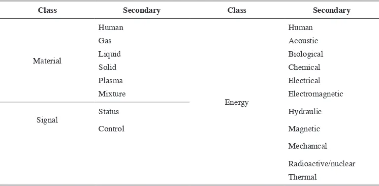
and secondary class of function and flow are shown in Tables 1 and 2, respectively. Similar to the function set, there are 3 distinct classes within the flow set of the functional basis. Within the primary class of the flow set, there are 3 main categories used to describe flow: applying functional models will facilitate design engineers to come up with a conceptual design of a product based on the customers’ needs.
Methodology
This section presents the application of Stone and Wood’s functional model derivation
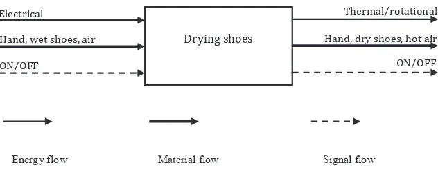
Task 1: Generate Black Box Model
product (or transformation of another flow) was considered and expressed in the verb- object format. Next, the functional model wasarranged with respect to time. The concept of parallel and sequential dependencies of flow and sub-functions wasapplied in this case. In the sequential function chain the sub-functions were performed in a specific sequence to generate the desired result (Stone and Wood, 2000).
Task 3: Aggregate Functional Chains into a Functional Model
The final task of functional model derivation was to assemble all functional
chains into a single model. To accomplish this task, the interface between the functional chains was identified.
Task 4: Derive Sub-solutions
In this task the potential solution of each sub-function wasidentified based on the designer’s experience and with the aid of the product catalogue.
Results and Discussion
In the development of the black box model of an electrical shoe dryer, one of the researchers acted as a customer and attempted to tell the
Table 1. Function examples from the reconciled functional basis of Hirtz et al. (2002)
Class Secondary Class Secondary Class Secondary
Branch Separate Control magnitude
Actuate Signal Sense
Distribute Regulate Indicate
Change Process
Stop
Channel Import Support
Export Stabilize
Transfer Convert Convert Secure
Guide Thermal
Connect Couple Provision Supply
Mix Store
Table 2. Flow examples from the reconciled functional basis of Hirtz et al. (2002)
Class Secondary Class Secondary
Material
Human
Energy
Human
Gas Acoustic
Liquid Biological
Solid Chemical
Plasma Electrical
Mixture Electromagnetic
Signal
Status Hydraulic
Control Magnetic
Mechanical
researchers about the the needs as a customer in relation to the product. At the end, a list of customer needs was produced and formed the basis for the black box development. For the of material, energy, and signal.
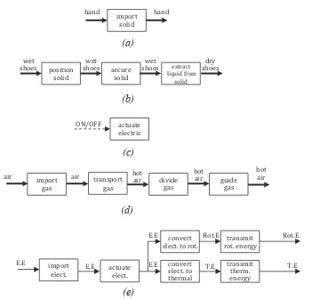
Five flow chains were developed for an electrical shoe dryer of which 3 flows were of material, 1 flow of energy, and 1 flow of signal. The 5 function chains for an electrical shoe dryer are shown in Figure 2. To designate a flow, the researchers thought of the necessary operations in the flow of hand, wet shoes, air, electrical energy, and ON/OFF from the ON/OFF. The functional chains were expressed in the standard design language (functional basis) as in Table 1. Functions and flows were combined in verb-object form for describing sub-functions.
For an electrical shoe dryer, the flow of air produces a sequential function chain as 4 sub-functions must operate on the flow of air before it exits the product, as shown in Figure 3(a). Parallel functional chains consist
of sets of sequential functional chains sharing 1 or more flow. Graphically, they are represented by a flow which branches in a functional model. Figure 3(b) shows the parallel functional chain of an electrical shoe dryer. In it, the flow of electricity branches to form parallel chains of sub-functions. The 2 chains operate independently of each other (the first is concerned with converting electricity to rotational energy and the second is concerned with converting electricity to thermal energy).
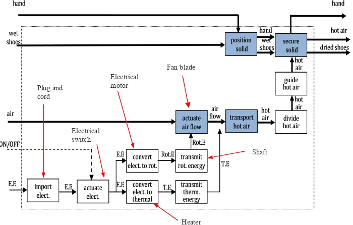
There are 4 interface points in the ‘transport gases’. At this interface the rotational energy is transmitted for actuating air flow, meanwhile thermal energy is transmitted to the flowing air to generate hot air. The flow of hand and wet shoes meet at the ‘position solid’ as the human hand is required to take the wet assembly of functional chains that are called a functional model of an electrical shoe dryer, as shown in Figure 4, expressed as the functional basis.
The first standard products/components to satisfy the sub-functions are identified.
Energy flow Material flow Signal flow
Drying shoes
ON/OFF
Hand, wet shoes, air
Electrical Thermal/rotational
Hand, dry shoes, hot air ON/OFF
(a)
(d) functional chain for the flow of air, and (e) functional chain for the flow of electrical energyimport
elect. actuate elect.
convert elect. to rot.
convert elect. to thermal
transmit therm. energy transmit rot. energy
import
gas transport gas
guide gas position
solid secure solid
E.E E.E E.E
E.E
T.E Rot.E
T.E Rot.E
air air hot air
hot air wet
shoes hand
hot air dry shoes hand
wet shoes
ON/OFF
divide gas
hot air
Figure 4. Functional model of an electrical shoe dryer expressed in the functional basis
Figure 5. The standard products/components for an electrical shoe dryer
Electrical motor
Heater Plug and
cord
Electrical switch
Fan blade
Shaft
Figure 5. The standard products/components for an electrical shoe dryer
As shown in Figure 5, there are 6 standard products/components that are able to satisfy the functions. For example, the sub-function to ‘convert electricity to rotational energy’ was satisfied by an electric motor and the function to ‘actuate electrical energy’ was satisfied by an electrical switch. Later on, the sketch of these products/components is drawn and the required basic properties i.e. structure,
form, material, dimensions, and surface of the product were determined to satisfy the other sub-functions. Figure 6 shows the initial concept design of an electrical shoe dryer.
Conclusions
(a)
Figure 6. Initial concept design of an electrical shoe dryer: (a) 2D design and (b) 3D design
in facilitating design engineering at the functional model of the product. The functional basis of Hirtz et al. (2002) was employed as the design language to describe sub-functions and flows of the product. In general, the application of the functional modelling approach is able to provide design engineers with the overall image of the product without the existence of the physical entity of the product. In addition, with the help of graphical representation this approachis able to facilitate the design engineer to implement the required function into the product. It was obvious that, in the derivation of functional modelling, the product and, thus, needs improvement.
Acknowledgment
Wiley & Sons Ltd., Bognor Regis, UK, 212p. Hirtz, J., Stone, R., McAdams, D., Szykman, S., and
Wood, K. (2002). A functional basis for engineering design: reconciling and evolving previous effort. Res. Eng. Des., 13(2):65-82. Hundal, M.S. (1990). A systematic method for
developing function structures, solutions and concept variants. Mech. Mach. Theory, 25(3):243-256.
Krus, D. and Grantham Lough, K. (2007). Applying function-based failure propagation in conceptual design. Proceedings of the 19th International
Conference on Design Theory and Methodology; September 4-7, 2007; Las Vegas, NV, USA, DETC 2007-35475.
Otto, K. and Wood, K. (2001) Product Design – Techniques in Reverse Engineering and New Product Development. Prentice Hall Inc., Upper Saddle River, NJ, USA, 1064p.
Pahl, G. and Beitz, W. (1996). Engineering Design: a Systematic Approach. 3rd ed. Springer, Berlin,
Germany, 617p.
Pugh, S., (1997). Total Design: Integrated Methods for Successful Product Engineering. Addison- Wesley Longman Ltd., Harlow, UK, 296p. Hutcheson, R., McAdams, D., Stone, R., and Tumer.,
Stone, R.B. and Wood, K.L. (2000). Development of functional basis for design. J. Mech. Design, 122(4):359-370.
Suh, N. (1990). The Principle of Design. Oxford University Press, Oxford, UK, 416p.
Ullman, D.G. (2003). The Mechanical Design Process. McGraw-Hill Professional, Boston, MA, USA, 415p.
Ulrich, K.T. and Eppinger, S.D. (2004). Product Design and Development. 3rd ed. McGraw-Hill/
Irwin, New York, NY, USA,366p.