“I hereby declare that this report is qualified in form of scope and quality to earn a
graduation in Bachelor of Electrical Engineering (Mechatronic)”
Signature :………
HIGH FREQUENCY ELECTRONIC BALLAST PROTECTION
CATHERINE MUNA ANAK GEORGE MALANG
This Report is Submitted in Partial Fulfillment of Requirements For The Degree of Bachelor in Electrical Engineering
(Mechatronic)
Faculty of Electrical Engineering Universiti Teknikal Malaysia Melaka
“I hereby declared that this report is a result of my own work except for the excerpts that have been cited clearly in the references”
Signature :………..
“I hereby declared that I have read through this report and found that it has comply the partial fulfillment for awarding the degree of Bachelor of Electrical Engineering
(Mechatronic)”
Signature : ………. Supervisor‟s Name : MR. ALIAS BIN KHAMIS Date : 22TH APRIL 2009
HIGH FREQUENCY ELECTRONIC BALLAST PROTECTION
CATHERINE MUNA ANAK GEORGE MALANG
ACKNOWLEDGEMENT
First of all we would to express our deepest thanks and gratitude to my supervisor, Mr. Alias Bin Khamis for their never-ending encouragement, moral support and patience during final year project. Without their help and guide line, we will not be able to complete the given tasks on time.
Next, our appreciation must be extended to our parents for their blessing and their understanding throughout completing this project. Thousands of thanks is dedicated to others family members who had share their opinion with us.
iv
ABSTRACT
ABSTRAK
vi
CONTENTS
CHAPTER TITLE
ACKNOWLEDGEMENT
PAGE
iii
ABSTRACT
CONTENTS
LIST OF TABLES
LIST OF FIGURES
LIST OF ABBREVIATION
LIST OFAPPENDIX iv v vi vii viii ix
I INTRODUCTION
1.0 Background 1.1Project Objectives 1.2Project Scopes 1.3Problem Statement 1.4Thesis outline 1.5Project Planning
1 2 2 3 3-4 4
II LITERATURE REVIEW
2.1 Electronic Ballast
2.2 Problems Caused By Electronic Ballast 2.3 Protection Alternatives
2.4 Full Bridge Rectifier
2.5 FAN7710(Ballast Control IC)
2.5.2 Oscillator 2.6 Filter 2.7 Summary 15-17 17-18 18
III METHODOLOGY
3.1 Flow Chart 3.2 OrCAD
3.3 Fluke Quality Analyzer
3.3.1 Measuring Lighting Load 3.3.1.1 Power and Power Factor 3.3.1.2 Inrush Current
3.3.1.2 Total harmonic Distortion 3.4 Illuminometer
3.4.1 Features
3.4.2 Operating instructions
3.4.2.1 Preparations for measurements 3.4.2.2 Measurement 19-20 21-24 25 26-27 27-30 30-31 32 32 33 33 33
IV RESULTS AND DISCUSSIONS
4.1 Calculation And Simulation 4.1.1 Electronic Ballast 4.1.1.1 Fourier Analysis 4.1.1.2 Transient Analysis
4.1.1.3 Steady-state analysis 4.1.2 Ballast Control IC (FAN7710)
4.2.2.1Operation Mode 4.2.2.2Preheating Mode
viii
4.2.2.3Shutdown Mode 4.3 Hardware and analysis 4.3.1 Circuit operation 4.3.2 Hardware
4.3.3 Electronic Ballast
4.3.4 Electronic ballast protection 4.3.5 Summary
43 44 44-45 46-47 47-50 50-51 52
V CONCLUSION
5.1 Recommendation
53-54 55-56
REFERENCES
APPENDIX A
LIST OF TABLES
NO TITLE PAGE
1.1 Gantt chart for project planning 4 2.1
3.1 4.1
Pin definition Illuminator features
Components of High frequency electronic ballast protection
13 32 46 4.2 Comparison between conventional electronic ballast and electronic
ballast protection 52 5.1 Advantage and disadvantage of electronic ballast and electronic
Ballast protection 54
5.2 Component list 55
x
LIST OF FIGURES
NO TITLE PAGE
1.1 Scope of construction electronic ballast with protection 2 2.1 Electronic ballast block diagram 6 2.2 Construction of electronic ballast 8
2.3 Full bridge rectifier 9
2.4 Positive cycle full bridge rectifier 10 2.5 Negative cycle full bridge rectifier 10 2.6 AC, half-wave and full wave rectified signal 11
2.7 IC FAN7710 12
2.8 Pin configuration 13
2.9 Internal block diagram 14
2.10 Resonant Inverter circuit based on LCC Resonant Tank 16 2.11 LCC transfer function in term of lamp impedance 17
2.12 Lowpass filter 17
3.1 Flow chart of Electronic ballast protection 19
3.2 Capture CIS 21
3.3 Schematic diagram 21
3.4 Simulation setting 22
3.5 Transient output file option 22
3.8 3.9 3.10 3.11 3.12 3.13 3.14 3.15 3.16
Fluke Quality Analyzer
Power and Power Factor Measurement Connection Power Menu
Lighting load connection Inrush Current Menu
Total Harmonic Distortion Measurement Connection Total Harmonic Menu
Illuminator Illuminator designations 24 25 26 28 29 30 30 31 32 4.1 4.2 4.3 4.4 4.5 4.6
Resonant lamp output stage
Resonant lamp output stage during steady state Simulation model for electronic ballast
Simulation result of lamp voltage Result of lamp current
Operation mode 36 37 39 39 40
4.7 Typical transient waveform 42
4.8 External shutdown circuit 43
4.9 4.10
Schematic of high frequency electronic ballast protection Test evaluation board
44 45 4.11 4.12 4.13 4.14 4.15 4.16 4.17 4.18
Front view of high frequency electronic ballast protection PCB layout
Curve of fluorescent lamp efficacy versus lamp operating frequency
Voltage and current for electronic ballast Power factor for electronic ballast
Total harmonic distortion voltage for electronic ballast Total harmonic distortion current for electronic ballast Voltage and current for electronic ballast protection
46 47 49 49 49 49 49 50 50 4.19 Total harmonic distortion voltage for electronic ballast
xii
4.20 Total harmonic distortion current for electronic ballast
protection 51
4.21 Power factor for electronic ballast protection 51 5.1 Typical application circuit for compact fluorescent lamp 55
LIST OF ABBREVIATION
DC – Direct Current
CFL – Compact Fluorescent Lamp
MOSFET – Metal-Oxide-Semiconductor Field-Effect Transistor IC – Integrated Circuit
xiv
LIST OF APPENDIX
NO TITLE PAGE
CHAPTER 1
INTRODUCTION
1.0Background
An electromagnetic radiation of a wavelength that is visible to the human eye is a defined for light or visible light. However, whether visible or nit, the light is often used to refer to electromagnetic radiation of all wavelength in the broader field of physics. The development of modern lamps is overcome after the discovery of electrical power and possibility of transmitted. Today, lamps is the electrical component which a very important in our life. Many of types of lamp are being manufactured as incandescent lamp, fluorescent lamp, and discharge lamp.
2
Electronic ballast is most popular two years ago because it more cheaper compare with magnetic ballast. But today, a request for electronic ballast from customer is reduced because it easy to damage from fault and light. By implementing the protection for the electronic ballast, it can be save energy and increase a lamp lift-time.
1.1Project objectives
The main objectives of this project are
1. Develop a high frequency electronic ballast protection for avoided from fault and light.
2. Develop an internal controller which is detects open-lamp condition without the expense of external circuitry.
3. Comparison between electronic ballast and electronic ballast with protection. 4. Enhance knowledge and an experience in project management and to carry out
the project
[image:20.612.112.549.422.468.2]1.2Project scopes
Figure 1.1: Scope of construction electronic ballast with protection
The scope of this project is consists of software, rectifier, FAN7710, and resonant filter. A software has used for simulation are OrCad and Multism. A full bridge rectifier uses four diodes in a bridge arrangement to achieve a full-wave rectification. It also uses to convert AC power to DC power. The FAN 7710 is a ballast control integrated circuit (IC) which is controls internal high-voltage stress. Then, the resonant filter will be uses to eliminate the undesired harmonic components. Lastly, a comparison between electronic ballast and electronic ballast with protection will be done by circuit analysis. The inverter component is not includes in scope of project because the half bridge inverter is already inside of FAN7710.
Software FAN7710 Resonant
Filter
The high frequency electronic ballast is an electronic control device that can save energy of the lighting system. However, the problem for electronic ballast is a short life-time because there is no any protection from fault and light. Now, the design of high frequency electronic ballast with protection must be perform four functions:
1. The circuit must be adversely affect other electrical devices with high frequency devices introduce harmonic distortion in the power circuit.
2. Construct a high-side driver built included an inverter inside.
3. Incorporates a preheating and ignition function to increase lamp life. 4. Assure that the circuit will remain stable and prevents stress on MOSFETs.
1.4Thesis outline
For the high frequency electronic ballast protection projects, the report will begin with design a one circuit for electronic ballast with a protection to delivers a 36W compact fluorescent lamp. It consists on five sections in detail. The section of this report is includes the introduction, literature review, methodology, results and discussions, and conclusion.
Firstly, in chapter one is consist of introduction for the project which is discussed about the characteristic of the lamp. For every type of lamp are different criteria. Beside that, the project objective, scope, problem statement and thesis outline for this chapter is included.
4
In chapter three, it will be include the methodology part. In this part, the technique and consideration that applied during carried out PSM1 is discussed. A simulation has done to get an expected result by simulate the design circuit before proceed to the hardware part.
For PSM1, the discussion and result is base on simulation and expected result. The simulation is done to the design circuit to ensure it can be functionally probably. The hardware part is not including in PSM1 because it will be proceed on PSM2. Lastly, the analysis is done according to the results.
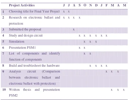
[image:22.612.105.551.332.677.2]1.5Project planning
Table 1.1: Gantt chart for project planning
Project Activities J J A S O N D J F M A M
1 Choosing title for Final Year Project x x
2 Research on electronic ballast and
protection
x x x x
3 Submitted the proposal x
4 Study and design circuit x x x x x x
5 Simulation x x x
6 Presentation PSM1 x x
7 List of components and identify
function of components
x x
8 Build and troubleshoot the hardware x x x x
9 Analysis circuit (Comparison
between electronic ballast and
electronic ballast with protection)
x x x
10 Written thesis and presentation
PSM2
CHAPTER 2
LITERATURE REVIEW
2.1 Electronic ballast
Electronic ballast design is becoming more common due to its superior performance. It outputs 10%-15% more light output, does not have the 50/60 cycles irritating hum, high frequency switching that does not have visible flicker to the human eyes, cooler and more reliable. Operating the ballast at higher frequency means that the design can be smaller and made compact. It utilizes the switching mode power supply technology electronic ballasts can be categorized into 3 categories as an instant start, rapid start and programmed start.
Instant start ballasts require an instant-start certified lamp and ignite a lamp in about 80 milliseconds or less using a high frequency electronic circuit. It starts the lamp without heating the cathodes by using a high voltage at around 600V. It is the most efficient energy type when used in installations where the lamps are not turned on and off regularly.
6
best life to the lamps and is used in applications where frequent ON/OFF of lights is required.
Self-oscillating electronic ballasts has been proposed as a potential energy saving proposition for several environments and makes the electronic ballasts versatile without increasing significant cost. Beside that, it‟s used to ensuring a characteristic avoiding complexity, maintaining its well-known reliability and simplicity. The electronic ballast is reduced in size and components numbers comparing traditional automatic systems. The energy saving system will be implemented by self-oscillating gate-driver in electronic ballast application.
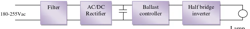
The high frequency electronic ballast is consists of rectifier, inverter, self-oscillating gate drive, and resonant filter. A bridge rectifier converts AC power to DC power. An inverter is used to converts DC power to AC power. A self-oscillating gate driver is used to switch on and off complimentary of transistors to produce a high frequency square wave of inverter output. The square wave is passed though the low-pass filter to eliminate the undesired harmonic components.
180-255Vac
[image:24.612.113.550.432.483.2]Lamp
Figure 2.1: Electronic ballast block diagram
For the bridge rectifier, it will contain four diodes and one bulk capacitor. The AC mains voltage is rectified by four bridges rectifying diodes and the DC supply voltage for the half bridge inverter is smoothed by a buffer capacitor. The DC/AC inverter is a half-bridge series-resonant parallel-loaded converter. A filter is used to minimize the disturbance towards the mains. To generated a high frequency square waveform, two of MOSFETs is used as a switches, and switch on and off position complementarily with a fixed dead time.
Filter AC/DC
Rectifier
Ballast controller