GRAPHICAL USER INTERFACE FOR WIRELESS PATIENT MONITORING
SYSTEM USING ZIGBEE COMMUNICATION
N. M. Z. Hashim, M. R. Anuar, A. Jaafar, M. Z. A. A. Aziz, A. Salleh and A. S. Ja’afar
Centre for Telecommunication Research and Innovation (CeTRI), Faculty of Electronic and Computer Engineering, Universiti Teknikal Malaysia Melaka (UTeM), Hang Tuah Jaya, 76100 Durian Tunggal, Melaka, Malaysia
E-Mail: [email protected]
ABSTRACT
Nowadays, heart related diseases are on the rise situation. In Malaysia, the proportion of patients is increasing day by day but the number of doctor and nurse slightly different situation. For this reason, the new propose graphical user interface for wireless patient monitoring system is proposed in order to help doctors and nurses to monitor their patient wirelessly for 24 hours by using a designated proposed device. This system runs as prototype to minimize the costing issue in the hospital. This system consists of software and hardware. Visual Basic Net 2010 software is used to design the graphical user interface (GUI) and Peripheral Interface Controller (PIC) 16F877A microcontroller is used as the hardware to implement the whole proposed system. This system is can be divided into three parts. There are three stages that involved in completing the system. The first is developing a program for the microcontroller, the second is transmitting the data from microcontroller to the personal computer (PC) using XBee module and the third is designing the GUI. In conclusion, the proposed GUI for wireless patient monitoring system facilitated the doctor and nurse in monitoring the patient and increased the efficiency of patient monitoring. For the future recommendation, additional sensor and alarm buzzer shall be added to the system as triggering the observer of the system.
Keywords: wireless monitoring system, zigbee communication, heart sensor, PIC16F877A microcontroller, visual basic net.2010.
INTRODUCTION
Heart related diseases are on the rise everywhere in the world. Cardiac arrest is quoted as the major contributor to sudden and unexpected death rate in the modern stress filled lifestyle around the globe. Therefore, doctor and nurse have difficulty to monitor the patient within 24 hours continuously. Thus, the proposed wireless patient monitoring system is a device to help doctors and nurses monitor their patient for 24 hours wirelessly. This system used Xbee Pro as the communication to send the patient data to the personal computer (PC). The range of this system is within 200 to 500 meter enough for 1 block. The patient data not only for dedicated PC, moreover it can also be viewed on other computers. The data will be sent to the computer and viewed 24 hours at the computer by using visual basic if there are unusual results from the patient heartbeat. PIC16F877A Microcontroller will be used to send the patient data to both doctor and nurse computer [1].
The main target for this system is to design a system which implemented a dedicated monitoring system using wireless connection. The data can be transmitted to the receiver (PC) wirelessly via XBee module. The objectives of this system are to analyze wireless monitoring patients using XBEE module that can be easier to monitor patient at hospital and design a friendly user GUI to display the receiver data. This system can be divided into three parts. The first part is developing program for microcontroller, the second part is transmitting the data from microcontroller to the PC using XBee module and the third part is designing the Graphical User Interface (GUI).
The proposed system used pulse heart sensor to obtain the heart beat reading. Wireless communication protocol as Zigbee communication is used in designing the
system [2]. As a computer based system the interactive, Visual Basic software is used to design graphical user interface (GUI) for the system.
LITERATURE REVIEW
C. Rotariu et al., suggested an integrated system for wireless monitoring of chronic patients and elderly [3]. The system was suitable for continuous long-time monitoring, as a part of a diagnostic procedure or can achieve medical assistance of a chronic condition. The Personal Server, in form of a PDA that running a monitor application received the physiological signals from monitoring devices, will activate the alarm when the monitored parameters exceed the preset limits and communicate periodically to the central server by using the Global System for Mobile Communication (GSM) or General Packet Radio Service (GPRS) connection. However, the system was useful for application that requires high bandwidth.
The wireless remote point of care patient monitoring system suggested by Ashwin K. et al., help patient's life, it can also helped patients for regular check to reduce the number of home visits which are now only required when special attention is needed [4]. This project is design and development wireless data acquisition from eight patient-worn sensors. This system uses Bluetooth technology for communication with a home based monitor which in turn relays this data to the remote healthcare facility using the internet. A few sensors are connected to demonstrate the concept of remote patient monitoring. Yet the system surely needs internet access. If the area is out of coverage, then the data cannot receive to remote healthcare facility.
the development of a module adopting a simple and popular technique, detecting the abnormalities in the bio signal of the patient in advance and sending an alert Short Message Services (SMS) to the doctor through Global System for Mobile (GSM) thereby taking suitable precautionary measures thus reducing the critical level of the patient [5]. Without the communication coverage, the data cannot receive and send to the module.
Sownyasudhan S. Manjunath S. suggested a system that used four smart sensors to detect the respective four pathological parameters of a person and interfacing the cell phone to this system to alarm the doctors [6]. Using wireless based low cost to monitor real-time pathological parameters of the subject and say it as a simple biomedical-caring system. This project is to get information about the condition of the critical subject which needs to be monitored round the clock, which is in ICU through wireless. The wireless Transmitter sends the details about incubator’s temperature voice level, heart rate and its movement to the destination point which is a doctor mobile and these details are displayed on the mobile screen in the form of Short Message Services (SMS), so that the doctor can analyze the condition from the place where he is sitting. This is the most basic foundation in the area of telemedicine application. The proposed system was expensive because it used many sensor e.g. temperature sensor, voice sensor, movement sensor and pulse rate sensor.
The suggested system interactive wireless medical information system that allowed patient instrumentation output data to be accessed and patient details to be entered by medical practitioners using mobile computing devices [7]. However the system has the shortage of coverage access limitation.
MATERIALS AND METHODS
Methodology
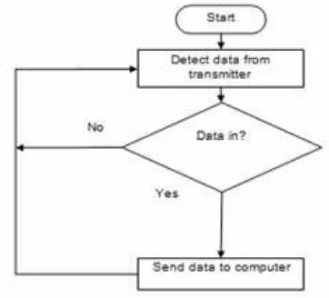
The backbone of this system is software program; including the design of circuit, data communication and system interfacing [8]. The data communication and all part must be tested in order to check the connection of the whole system [9]. Furthermore, every parts of the system are tested individually to ensure the functionality before running system at large [10]. The block diagram of the system and the flow chart for transmitter and receiver module are shown as figure below:
Figure-1. Block diagram of the system.
Figure-2. Flow chart of transmitter module.
Figure-3. Flow chart of receiver module.
Configuration of the XBee modules is essential in wireless communication part. For configuring the XBee modules, it is involves the installation of X-CTU software. Both the XBee Pro series are using the same installer. After setting up the XBee module is completed, the next process is testing functionality of the both XBee. Terminal at X-CTU software is opened and typed any word to make sure both of XBee modules are communicate each other [11, 12].
Design circuitry
In this system, there are 3 LED (green, yellow and red) been used. Every LED has its own function. For the green LED it indicates that XBee function or not and red LED shows every 6 seconds data was send from transmitter to receiver. Yellow LED shows either PIC has power supply or not. The heartbeat reading is taken by pulse sensor. The output will be displayed at the GUI using visual basic software [13-16].
ISIS 7 and in Figure-5 the circuit was transferred to ARES 7 for etching purpose.
Figure-4. End device schematic diagram.
Figure-5. PCB layout.
XBEE pro configuration
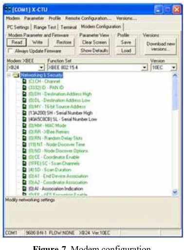
The XBee module need to be set before it can be used as serial communication between hardware and software for this system [22, 23]. This setting requires an installation of X-CTU software created to configure the XBee module by Digi Corp. Both XBee and XBee Pro series are using the same installer. For the configuration of XBee Pro module, it can be done by using X-CTU software. The software will automatically detect available COM port. By clicking the “Test/ Query” button the software began to interact with the module to test the selected COM port. Figure-6 shows that the message box appears if the COM ports are OK.
Figure-6. COM port testing.
Next, at the modem configuration, the specified information about the module can be modified according to the user specification. In order to make a two ways connection between these modules, a few changes need to be done by modified the selected properties as shown in Figure-7.
Figure-7. Modem configuration.
RESULTS AND DISCUSSIONS
Figure-8. Show program data flow model.
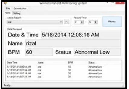
Figure-9. GUI display the patient name, beats per minute and status patient.
The Figure-9 shows the GUI for patient monitoring program [24]. This system can select the patient name and record the data, put minutes/second to record the heart rate, and by click ‘record’ button. The data is recorded by every selected minutes/second. This system is very effective to monitor all the patients’ data for every minute. In this system, the value of heart beat reading is been set for three criteria, abnormal low for heart beat from “0” until “60”, normal “61” until “100” and lastly abnormal high more than “100”. The result will be shown in Graphical User Interface (GUI). Every changes of heartbeat reading will be updated through the
system’s GUI. Thisdata will be saved in Excel format, the
data include date and time, patient condition and heart beat reading.
Figure-10. Patient data result.
CONCLUSIONS
In conclusion, this wireless patient monitoring system facilitated the doctor and nurse in monitoring the patient and increases the efficiency of patient monitoring. This system achieved the target as implemented the monitoring system by using wireless medium. The data can transmit to the receiver (PC) via wireless and display the data at the PC. This system can solve the major problem in most hospitals that is lack of doctors, a significant difference between the doctor and patient ratio is quite high. For the future recommendation, additional sensor and alarm buzzer shall be added to the system as triggering the observer of the system.
ACKNOWLEDGEMENT
We are grateful to Centre for Telecommunication Research and Innovation (CeTRI) and Universiti Teknikal Malaysia Melaka (UTeM) for their kind and help for supplying the electronic components and giving their laboratory facility to complete this study.
REFERENCES
[1] N. M. Z. Hashim and M. S. Sizali. 2013. Wireless
Patient Monitoring System. Int. J. Sci. Res. 2(8): 250-255.
[2] H. Marko and M. Maija. 2007. Wireless System for
Patient Home Monitoring. In: 2007 2nd International
Symposium on Wireless Pervasive Computing. pp. 442-446.
[3] C. Rotariu, H. Costin, G. Andruseac, R. Ciobotariu
and F. Adochiei. 2011. An Integrated System for Wireless Monitoring of Chronic Patients and Elderly
People. In: 15th International Conference on System
Theory, Control and Computing (ICSTCC). pp. 1-4.
[4] A. K. Whitchurch, J. K. Abraham, S. Member and K.
[5] R. Sukanesh, S. Palanivel Rajan, S. Vijayprasath, N. S. Aishwarya and P. Gracy Angela. 2010. Intelligent wireless mobile patient monitoring system. In: 2010 International Conference on Communication Control and Computing Technologies. pp. 540-543.
[6] S. Sowmyasudhan and S. Manjunath. 2011. A
Wireless Based Real-time Patient Monitoring System. Int. J. Sci. Eng. Res. 2(11): 1-7.
[7] M. D. S. B and A. Postula. 2008. Wireless Interactive
System for Patient Healthcare Monitoring using
Mobile Computing Devices. In: 2nd International
Conference on Signal Processing and Communication Systems. No. Mcd. pp. 0-5.
[8] PIC 16F87XA Memory Organization Tutorial.
MicrocontrollerBoard.com, 2012. [Online]. Available: http://www.microcontrollerboard.com/pic_memory_or ganization.html.
[9] N. M. Z. Hashim, S. H. Husin, A. S. Ja’afar and N.
Hamid. 2013. Smart Wiper Control System. Int. J. Appl. or Innov. Eng. Manag. 2(7): 409-415.
[10]MICROCHIP PIC16F87XA Data Sheet, 28/40/44-Pin
Enhanced Flash Microcontrollers. Microchip Technology Inc, 2008. [Online]. Available: ww1.microchip.com/downloads/en/DeviceDoc/39582 b.pdf.
[11]N. M. Z. Hashim, M. H. A. Halim, H. Bakri, S. H.
Husin and M. M. Said. 2013. Vehicle Security System Using Zigbee. Int. J. Sci. Res. Publ. 3(9): 1-6.
[12]N. M. Z. Hashim, A. S. Jaafar, N. A. Ali, L.
Salahuddin, N. R. Mohamad and M. A. Ibrahim. 2013. Traffic Light Control System for Emergency Vehicles Using Radio Frequency. IOSR J. Eng. 3(7): 43-52.
[13]N. M. Z. Hashim, N. A. Ibrahim, N. M. Saad, F.
Sakaguchi and Z. Zakaria. 2013. Barcode Recognition System. Int. J. Emerg. Trends Technol. Comput. Sci. 2(4): 278-283.
[14]N. M. Z. Hashim, N. H. Mohamad, Z. Zakaria, H.
Bakri and F. Sakaguchi. 2013. Development of Tomato Inspection and Grading System using Image Processing. Int. J. Eng. Comput. Sci. 2(8): 2319-2326.
[15]N. M. Z. Hashim and S. N. K. S. Mohamed. 2013.
Development of Student Information System. Int. J. Sci. Res. 2(8): 256-260.
[16]N. M. Z. Hashim and N. Arifin. 2013. Laboratory
Inventory System. Int. J. Sci. Res. (IJSR…, 2(8): 261264.
[17]N. M. Z. Hashim, N. A. Ali, A. Salleh, A. S. Ja’afar
and N. A. Z. Abidin. 2013. Development of Optimal Photosensors Based Heart Pulse Detector. Int. J. Eng. Technol. 5(4): 3601-3607.
[18]N. M. Z. Hashim, N. M. T. N. Ibrahim, Z. Zakaria, F.
Syahrial and H. Bakri. 2013. Development New Press Machine using Programmable Logic Controller. Int. J. Eng. Comput. Sci. 2(8): 2310-2314.
[19]N. M. Z. Hashim, A. F. Jaafar, Z. Zakaria, A. Salleh
and R. A. Hamzah. 2013. Smart Casing for Desktop Personal Computer. Int. J. Eng. Comput. Sci. 2(8): 2337-2342.
[20]N. M. Z. Hashim, N. A. A. Ali, A. S. Ja, afar, N. R.
Mohamad, L. Salahuddin and N. A. Ishak. 2013. Smart Ordering System via Bluetooth. Int. J. Comput. Trends Technol. 4(7): 2253-2256.
[21]N. M. Z. Hashim and N. B. Hamdan. 2013. Flood
Detector Emergency Warning System. Int. J. Eng. Comput. Sci. 2(8): 2332-2336.
[22]Xbee/Xbee-PRO OEM RF modules. [Online].
Available: www.MaxStream.net.
[23]Compiler- CCS Inc. [Online]. Available:
http://www.microchip.com/stellent/idcplg?IdcService =SS_GET_PAGE&nodeID=2519¶m=en025441# P194_11333.
[24]Introducing to Visual Studio. Net. 2012. [Online].