DESIGN AND DEVELOPMENT OF GRAPHICAL USER INTERFACE (GUI) FOR UNDERWATER VEHICLE
GOH JOEN SAM
“I hereby declared that I have read through this report entitle “DESIGN AND DEVELOPMENT OF GRAPHICAL USER INTERFACE (GUI) FOR
UNDERWATER VEHICLE” and found that it has comply the partial fulfillment for awarding the Bachelor of Mechatronic Engineering.”
Signature : ...
Supervisor : Pn. Fadilah binti Abdul Azis
DESIGN AND DEVELOPMENT OF GRAPHICAL USER INTERFACE (GUI) FOR UNDERWATER VEHICLE
GOH JOEN SAM
This Report is Submitted in Partial Fulfillment of Requirements for Bachelor of Mechatronic Engineering.
Faculty of Electrical Engineering
UNIVERSITI TEKNIKAL MALAYSIA MELAKA
I declare that this report entitle “Design and development of graphical user interface (GUI) for under water vehicle” is the result of my own research except as cited in the references. The report has not been accepted for any degree and is not concurrently submitted tin candidature of any other degree.
Signature : ...
Name : GOH JOEN SAM
I
ACKNOWLEGEMENT
SPECIAL THANK
To Almighty GOD
To My Parent
To Pn. Fadilah binti Abdul Azis
To Mohd Shahrieel bin Mohd Aras
To Tan Chee Chien
To Mdnash Kumar
To Kong Teck Long
To my classmates
To all of my friends
&
II
ABSTRACT
III
ABSTRAK
IV
2.1.2 Fact of underwater vehicle 4
2.1.3 Application of ROV 5
2.1.4 Construction of ROV 6
2.1.5 Classification of ROV 7
2.2 Vision system for underwater vehicle 8
2.3 Underwater camera model 10
2.4 Vision system design (control) 11 2.5 Graphical User Interface (GUI) 12
V 3.6 The control of underwater servo motor 23
3.6.1 Microcontroller 24
3.6.2 UART 27
3.6.3 SK40C 28
3.6.4 Underwater servo motor 29
3.7 Experiment 32
3.7.1 Experiment 1: Camera movement testing 32 3.7.2 Experiment 2: Camera vision testing 34
3.8 Testing of GUI 36
3.9 Project Planning 36
4 RESULT 37
4.1 The design of the interface 37 4.2 The function require for GUI 40 4.3 Analysis for coding of the GUI 48 4.4 Analysis for camera movement 48
4.5 Analysis for camera view 52
4.6 Discussion 56
5 CONCLUSION AND RECOMMENDATION 57
5.1 Conclusion 57
5.2 Recommendation 59
REFERENCE 60
VI
LIST OF TABLE
Table 2.1: History of ROV ... 4
Table 2.2: Application of ROV ... 5
Table 2.3: Classification of ROV ... 7
Table 3.1: Hot Key of the GUI ... 19
Table 3.2: Specification of PIC16F877A ... 25
Table 3.3: The details of SK40C ... 28
Table 3.4: Specification of HS-5646WP ... 30
Table 4.1: Position of camera ... 49
Table 4.2: Time taken for camera movement in the air ... 50
Table 4.3: Time taken for camera movement underwater ... 50
Table 4.4: Rating of camera view ... 52
VII
LIST OF FIGURE
Figure 2.1: Underwater colour modification ... 8
Figure 2.2: Classification System for Underwater Image Collection Systems [7] ... 9
Figure 2.3: Underwater vehicles equipped with under water cameras [8] ... 11
Figure 2.4: Cable payout meter ... 13
Figure 2.5: five important modules to design GUI ... 14
Figure 3.1: Flow Chart of PSM ... 17
Figure 3.2: Project Overviews ... 18
Figure 3.3: Overall flow chart of project ... 19
Figure 3.4: K-Chart- Layer view of design and development of an ROV ... 20
Figure 3.5: Tree objective- the consideration of ROV making ... 21
Figure 3.6: New Project ... 21
Figure 3.7: Drag and drop ... 22
Figure 3.8: Properties ... 22
Figure 3.9: Coding Page ... 23
Figure 3.10: Debugging... 23
Figure 3.11: Overall flow of control ... 23
Figure 3.12: PIN reference of PIC16F877A ... 25
Figure 3.13: Flow chart for MicroC ... 26
Figure 3.14: Connection of USART and PIC [15] ... 27
Figure 3.15: Hardware of SK40C ... 28
Figure 3.16: Connection of ICSP programmer and UART via SK40C ... 29
Figure 3.17: HS-5646WP & its direction due to Pulse width provided ... 29
Figure 3.18: Step up voltage circuit ... 31
Figure 4.1: Main windows of ROV ... 37
Figure 4.2: View Camera ... 38
Figure 4.3: Summary ... 38
Figure 4.4: The control windows of ROV ... 39
VIII
Figure 4.6: Camera source select ... 41
Figure 4.7: Button for function of camera ... 41
Figure 4.8: UART connection ... 42
Figure 4.9: Button for camera movement ... 43
Figure 4.10: Main windows coding ... 44
Figure 4.11: coding for calling camera driver ... 46
Figure 4.12: Coding for communication between VB and MicroC ... 47
Figure 4.13: Analysis of experiment 1 ... 51
1
CHAPTER 1
INTRODUCTION
1.1 Background
Water is the major composition on earth as it covered 70% of earth surface. However, it seems difficult for human to explore the underwater nature. The major obstacle faced by the underwater vision system is the extreme loss of colour and contrast when submerged to any significant depth whereby the image quality produced is low. The ocean is currently the largest body of mass which covered seventy percent of Earth, but still remains the least explored. Modern area of research and development had discovered some equipment that can be used for the underwater application such as remotely operated underwater vehicle (ROV) and the latest invention is designing the Autonomous Underwater Vehicles (AUV). It has the potential in furthering the exploration of the deep sea.
Implementation vision system together with AUV would be the most efficient system created for capturing and recording underwater images. This invention had replace the conventional waterproof camera that been used before. Lots of benefits earn from this new system such as this system is ease to conduct and convenient to be use.
2 1.2 Problem Statement
Human cannot work effectively in underwater yet viewing the condition inside. These problems happened when scientist needs to do inspection or research in some unknown river, police needs to do investigation under the water, marine needs to rescue people or searching item under the sea and many more.
It is happened to be lot of difficulties and inconvenient for human to do their jobs underwater when they facing the condition such as in the deep sea, toxic water, dangerous area and etc. Furthermore, the time period for human to work underwater is also limited. Moreover, there is also lack of professional diver and even if it have, the cost for the diver is expensive. Nonetheless, it was always a troublesome matter due to a lot of issues for human in any works. Hence, it will be a huge trouble in doing any jobs underwater.
Although, there are already a lot of machine such as AUV or ROV in the market which helps for underwater jobs, however the machine is all from overseas country and none of them is made in our own country, Malaysia. For sure, the price of these machines is very expensive, even for only a small size of ROV or AUV. Other than that, the function and the ability of the machine are also limited.
Last but not least, the ability of vision control and a user friendly Graphical user interface (GUI) is also a major problem for these machines. For the primitive of the underwater machine, its vision is all control by the body of the machine itself, in the other words, the vision is not flexible. Besides that, the GUI is very complicated and even some of the machine don does not use GUI. Therefore, the underwater jobs will definitely become inconvenient with such this problems assisted.
3 1.3 Project objectives
The main objective of this project is to design and develop the graphical user interface (GUI) of an underwater vehicle. The main focus of the machine is on the vision part and the GUI for the whole machine including the control of the vehicle, the control of the vision and data storing thru computer. In order to achieve the goal of this project, several knowledge such as Visual basic .Net, microcontroller communicates, solid works, design based on user request are need to be understand. In order to hit the main objective, there are also several objectives have to be taken concern:
a) To design a GUI program with useful functions and features for a remotely operated underwater vehicle (ROV).
b) To study about the communication system between the vehicle and computer by using visual basic.
c) To do the research which is vital and correlated to the underwater vision.
d) To create a mechanism to hold the camera of the ROV in order to be controllable by itself.
1.4 Scope
This project is mainly focusing on the vision part of the vehicle only. The camera of the vehicle is using the current available underwater camera, SCA0156-30M from the brand of video surveillance. Besides that, this project will only use Visual Basic to create the GUI and Micro Controller (MicroC) to control the camera movement. The GUI is based on the creativity to suit the program needs.
Limitation:
a) The depth of the water for submerging the ROV is just about 5m deep. b) The clear vision of the vehicle under water is not more than 50inch. c) Pool and river is the only available medium for submerging the ROV. d) A wired connection of the camera to the PC.
4
CHAPTER 2
LITERATURE REVIEW
2.1 Background Theory
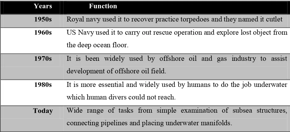
2.1.1 History of ROV
Table 2.1: History of ROV
Years Function
1950s Royal navy used it to recover practice torpedoes and they named it cutlet 1960s US Navy used it to carry out rescue operation and explore lost object from
the deep ocean floor.
1970s It is been widely used by offshore oil and gas industry to assist development of offshore oil field.
1980s It is more essential and widely used by humans to do the job underwater which human divers could not reach.
Today Wide range of tasks from simple examination of subsea structures, connecting pipelines and placing underwater manifolds.
2.1.2 Fact of underwater vehicle
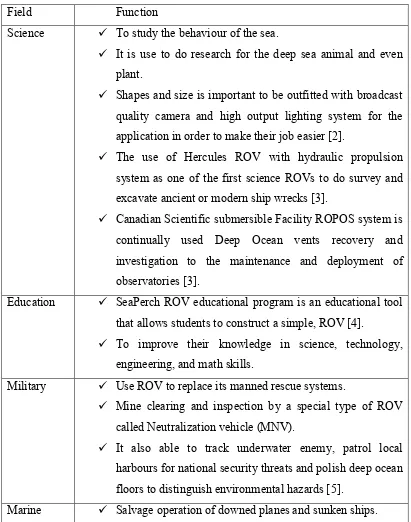
5 recommended. While the majority of oil & gas industry uses the ROVs to help their jobs; other applications include science, military and salvage [1].
2.1.3 Application of ROV
Shapes and size is important to be outfitted with broadcast quality camera and high output lighting system for the application in order to make their job easier [2].
The use of Hercules ROV with hydraulic propulsion system as one of the first science ROVs to do survey and excavate ancient or modern ship wrecks [3].
Canadian Scientific submersible Facility ROPOS system is continually used Deep Ocean vents recovery and investigation to the maintenance and deployment of observatories [3].
Education SeaPerch ROV educational program is an educational tool that allows students to construct a simple, ROV [4].
To improve their knowledge in science, technology, engineering, and math skills.
Military Use ROV to replace its manned rescue systems.
Mine clearing and inspection by a special type of ROV called Neutralization vehicle (MNV).
It also able to track underwater enemy, patrol local harbours for national security threats and polish deep ocean floors to distinguish environmental hazards [5].
6
Buoyancy is a necessity that can be provided by conventional R.O.V, which are built up by a large flotation pack that put on top of an aluminium chassis. Material which is normally be used for the purpose of flotation is syntactic foam. A variety of sensors have to be accommodated in order to run the system and its can be placed by fitting the compatible tool sled at the bottom of the system.
There are two separate layers in the overall system by placing two different components loads at the top and bottom according to the gravitation logics. Hence, the heavy components will be placed at the bottom while light components will be placed at the top to provide a large separation in between the canter of buoyancy and gravity in the overall system. Further illustrates, it will help to achieve a strong stability and much stiffer to do the work underwater.
To enhance full control, the thruster must be in three axes. Camera, lights and manipulators are usually built in front of the vehicle; however, it may be in the rear to help maneuvering. Next, the electrical cables must be run inside oil-filled tubing to protect them from rusting in seawater.
7 2.1.5 Classification of ROV
Table 2.3: Classification of ROV
Type Size/weight Ability
Micro Less than 3kg Enter small pipeline, small cavity or sewer.
Mini Around 15kg Diver alternative
Easy to carry
General Less than 5HP Gripper have been installed, able to carry sonar, used on light application Working depth less than 1000m.
Light work class
Less than 50HP Able to carry manipulators Made from polymers
Working depth less than 2000m
Heavy work class
Less than 220HP Able to carry at least 2 manipulators. Working depth less than 3500m.
8 2.2 Vision system for underwater vehicle
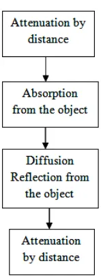
The most important basic improvement is actually based on colour space conversion, chromaticity histograms, colour equalization and normalization. Basically, the colour perception of an object is depends on physical, physiological and psychological and components such as spectral composition of light, spectral reflectance of the object, transmission of the light in the medium, and the visual system of the observer. Figure 2.1illustrated the process of underwater colour modification.
Figure 2.1: Underwater colour modification
9 Image processing, robot vision image analysis and machine vision is the terms that should always be stressed when discussing about image. There is usually to have common characteristics in terms of techniques and applications that been used. This shows that the techniques used and developed in these fields are very similar, or it can be known as one field with variety of names.
Those classifications are used to demonstrate the relationship between image range, camera light separation and the limiting factors in underwater image collection. For short ranges photo capturing, it need only a simple system with a good camera and controllable light beam to be able to produce good quality of pictures as underwater. If longer ranges are desired, the separation of lights and cameras will be key point to affect the quality of photo. The reason is, they present substantial advantages in that backscatter and this must be reduced substantially. [7]
10 2.3 Underwater camera mode
There are numerous kinds of marine researches are enthusiastically progressed by research institutes and universities around the world. Basically, researches about the deep-sea get a lot of attention because it is inseparably connected to various important matters such as the earth environment issue. Therefore underwater platforms like underwater vehicles (UVs) and sea-bottom stations have recently contributed. The type of UVs are classified broadly into two categories; manned underwater vehicles (MUVs) and the unmanned underwater vehicles. And moreover, the unmanned underwater vehicles are classified into remotely operated vehicles (ROVs) and autonomous underwater vehicles (AUVs) [8].
Most of the MUVs and ROVs is equipped with manipulators to build and maintain underwater structures and collect various marine samples. The operators, who board on MUVs and support ships for ROVs, control them by watching the TV camera image which appears the field circumstance. And AUVs are applied not only to survey the seafloor topography and under the sub seafloor structure using acoustic sensors but also to take many camera images of the seafloor in order to make the mosaic image which is composed of them. Meanwhile, the sea-bottom stations observe not only the seafloor condition such as the crustal movement and the plate boundary earthquake but also the submarine landslide and the biology of deep-sea organism using TV cameras [9].
11
Figure 2.3: Underwater vehicles equipped with under water cameras [8]
2.4Vision system design (control)
The vision sensing system bring the camera images as input, and outputs the pixel locations of the centroids in image coordinates of the target mooring. Besides that, the output is to identify the vision system has successfully matched a pixel group to that marker or not. The architecture is partitioned into three components: segmentation, prediction, and correspondence.
A. Segmentation
12 B. Correspondence
Correspondence is identified by comparing each candidate pixel region, or blob, with predicted profile of markers. The comparison of blob and markers is including centroid, coordinates, area, aspect ratio, average intensity and average gradient. Multiple markers are selected for matching with the current image. First, each blob is compared to markers for best matching in term of the characteristics mentioned above. Next, best matching are elected and matches are enunciated. However, when the entire matching are not satisfied, then no match is made and that systems will shows as unavailable to the estimator and the prediction step of vision processing [11].
.
C. Prediction
The current matched blob measurements is used in the prediction step of vision processing to update the profiles related with the fiducially marker set. Weighted average of the pass profile vector and current measurement is used in the update in affecting a low pass filter on the measurements. Future implementations of this system will strongly influence by the estimator about motions of the vehicle and target to predict more perfectly the estimated changes in the blob vector, parallel to the image coordinate prediction step [11].
2.5 Graphical User Interface (GUI)
The control system consists of a sub-sea controller with inputs for cable payout amount, cable payout speed, environmental status (temperature and humidity) and outputs to control the cable payout mechanism servos drives. A PIC microcontroller was used for the controller used a PIC microcontroller as to provide digital and analogue I/0 and a serial RS-232 link to the topside control GUI software.

![Figure 2.2: Classification System for Underwater Image Collection Systems [7]](https://thumb-ap.123doks.com/thumbv2/123dok/560305.66133/21.595.92.543.394.587/figure-classification-underwater-image-collection-systems.webp)
