UNIVERSITI TEKNIKAL MALAYSIA MELAKA
DEVELOPMENT OF CUSTOMIZED HMI CONTROL SYSTEM
FOR MAP 202
This report submitted in accordance with requirement of the Universiti Teknikal Malaysia Melaka (UTeM) for the Bachelor’s Degree of Electronics Engineering
Technology (Industrial Electronics) (Hons.)
by
AKMAL HAKIM BIN YUKHANIS
B071210158
910922-10-5961
FACULTY OF ENGINEERING TECHNOLOGY
i
DECLARATION
I hereby, declared this report entitled “Development of Customized HMI Control System for MAP 202” is the results of my own research except the works that have
been cited clearly in references.
Signature :
Author’s Name : Akmal Hakim Bin Yukhanis
ii
APPROVAL
This report is submitted to the Faculty of Engineering Technology of UTeM as a partial fulfillment of the requirements for the degree of Bachelor’s Degree of Electronics Engineering Technology (Industrial Electronics) (Hons.). The member of the supervisory is as follow:
iii
ABSTRAK
iv
ABSTRACT
v
DEDICATION
vi
ACKNOWLEDGEMENT
Firstly, I would like to thank to Allah for giving me a lot of strength and guidance while doing this project until completing this report.
I would like to express my highest appreciation to my supervisor of this project, Mr Shamsul Fakhar Bin Abd Gani and also my previous supervisor, Mr Ahmad Nizam Bin Mohd Jahari @ Mohd Johari for their patience, guidance and effort in guiding me in this project. Not to forget also, Mr Shukri as lab technician who always helps me by giving opinion and suggestion during this project.
Besides, I also would like to express my appreciation to my beloved parents and family for always giving me moral support and also blessing during my undergraduate in Technical University of Malaysia Malacca (UTeM).
Last but not least, my whole gratitude goes to who may involve directly or indirectly for their contribution while completing this project. Without them all, I may not able to complete my Final Year Project successfully.
vii
LIST OF ABBREVIATIONS, SYMBOLS AND NOMENCLATURE ... xiv
CHAPTER 1 ... 1
INTRODUCTION ... 1
1.1 Project Introduction ... 1
1.2 Problem Statement ... 2
1.3 Project Objectives ... 2
1.4 Project Scope ... 2
1.5 Project Methodology ... 3
1.6 Project Outline ... 4
CHAPTER 2 ... 6
LITERATURE REVIEW ... 6
2.1 Introduction ... 6
2.2 MAP 202 Handling System ... 7
2.3 Programmable Logic Controller (PLC) ... 8
viii
2.3.1.1 Execution Condition ... 11
2.3.1.2 Operand Bit ... 12
2.3.1.3 Logic Block ... 12
2.3.1.4 Instruction Block ... 12
2.3.1.5 Mnemonic Code ... 13
2.3.1.6 CPM2A Programmable Logic Controller ... 13
2.4 Human Machine Interface (HMI) ... 14
2.5 HMI Software... 16
2.7.2 Vacuum Pressure Sensor ... 20
2.8 Communication Cable ... 21
2.8.1 RS-232 Cable ... 21
3.2.1 Research information on MAP 202 and HMI ... 26
3.2.2 Develop Program ... 26
3.2.3 Testing Program Performance ... 26
3.2.4 Troubleshooting Program ... 27
3.2.5 Design Interface ... 27
ix
3.2.7 Finishing ... 28
CHAPTER 4 ... 29
RESULT AND DISCUSSION ... 29
4.1 Introduction ... 29
4.2 Result and Analysis ... 29
4.2.1 Control Strategy ... 30
4.2.2 Ladder Diagram Programming ... 33
4.2.2.1 Input/Output Assignment Table ... 33
4.2.2.2 Control Circuit ... 35
4.2.2.3 Power Circuit ... 36
4.2.2.4 Work Bit Circuit ... 37
4.2.2.5 Timer Circuit... 39
4.2.3 Indicator ... 39
4.2.5 Allocating address ... 46
4.2.6 Finishing ... 46
CHAPTER 5 ... 48
CONCLUSION AND RECOMMENDATION ... 48
5.1 Introduction ... 48
x
5.3 Problems Faced During Project ... 49
5.4 Future Recommendation ... 49
APPENDICES ... 50
APPENDIX A1 ... 51
APPENDIX A2 ... 52
APPENDIX B ... 53
APPENDIX C ... 54
APPENDIX D ... 55
xi
LIST OF TABLES
No Title Page
1 Table 2.1: Differentiation between Hard Wired Logic and PLC 9 2 Table 2.2: Differentiation of Conventional PC screen and HMI 15
3 Table 4.1: Sequence table 30
4 Table 4.2: Input Assignment Table 33
5 Table 4.3: Output Assignment Table 33
6 Table 4.4: Internal Relay Assignment Table 34
7 Table 4.5: Timer Assignment Table 35
xii
LIST OF FIGURES
No Title Page
1 Figure 2.1: Project Overview 7
2 Figure 2.2: Layout of MAP 202 8
3 Figure 2.3: NO Contact Relay and NC Contact Relay 10
4 Figure 2.4: Basic structure of PLC Programming 11
5 Figure 2.5: Condition of NO and NC on ladder diagram 11
6 Figure 2.6: Example of Mnemonic code of PLC 13
7 Figure 2.7: CPM2A Programmable Controller Module 14
8 Figure 2.8: Example of touch screen technology 15
9 Figure 2.9: Complete I/O Function 15
10 Figure 2.10: CX-Programmer software 16
11 Figure 2.11: NB-Designer software 17
12 Figure 2.12: Example of GRAFCET 18
13 Figure 2.13: Basic construction of Reed switch 20
14 Figure 2.14: Construction of Vacuum Sensor 21
15 Figure 2.15: RS 232 Pins Connection 22
16 Figure 2.16: Direct Connection to Host RS-232 Interface 22 17 Figure 2.17: Differentiation between USB Type A and B 23
18 Figure 2.18: USB Type A and B Pin out 23
19 Figure 3.1: Flowchart of project 25
xiii
21 Figure 4.2: GRAFCET for Initial Condition 32
22 Figure 4.3: Control Circuit using KEEP instruction for Step 2 36
23 Figure 4.4: Power circuit for Cylinder A 37
23 Figure 4.5: Power circuit for Cylinder B 37
24 Figure 4.6: Relation between control circuit and work bit circuit 38 25 Figure 4.7: Automatic and manual operation work bit 38 26 Figure 4.8: Timer circuit for manipulator insertion cover 39
27 Figure 4.9: Programming for Red indicator lamp 40
28 Figure 4.10: Indicator Tower 40
29 Figure 4.11: Login window interface 41
30 Figure 4.12: Main window Interface 42
31 Figure 4.13: About window Interface 42
32 Figure 4.14: Process condition window 43
33 Figure 4.15: Actuator condition window 43
34 Figure 4.16: Alarm Pop up window 44
35 Figure 4.17: Fast Selection window 45
36 Figure 4.18.: Screensaver window 45
37 Figure 4.19: Address Tag for input and output interface 46
38 Figure 4.20: RS-232 Communication setting 47
xiv
LIST OF ABBREVIATIONS, SYMBOLS AND
NOMENCLATURE
GRAFCET - Graphe Fonctionnel de Commande Etapes-Transitions
HMI - Human Machine Interface
NC - Normally closed
NEMA - the National Electrical Manufacturing Association
NO - Normally open
PC - Personal Computer
1
CHAPTER 1
INTRODUCTION
1.1 Project Introduction
Generally, the control system of an automation plant is a brain for their whole operation. Control system consists of collection of electronic devices and equipment to ensure the purpose of obtaining desired output with desired performance of a process or a manufacturing activity. As a result of rapid advancement of technology, a complicated control task can be accomplished with a highly automated control system, which may in form of Programmable Logic Controller (PLC) or possibly a host computer. (James, 2010)
2
1.2 Problem Statement
Computer always been a choice when it comes to control and monitor process purposes. It can directly interact what is displayed by user with touch pad or mouse controller. Nowadays, in industry or other several situations, using mouse system do not allow fast responds or gratify interaction to user because it will slow down the time operation of a process.
The MAP 202 supports the study of handling techniques. This machine can only be handled by using push buttons for automatic and manual operation. This project to develop the control system of MAP 202 by using Human Machine Interface by improve it to latest technology applied in industry. By implementing it, the station is easier to control.
1.3 Project Objectives
The objectives of this project are as follow:
1. To design and develop control strategy to control MAP 202 station.
2. To develop Human Machine Interface (HMI) that can integrate with MAP 202 station.
3. To implement the control system and HMI on MAP 202 station.
1.4 Project Scope
3
1.4.1 Familiarization on MAP 202 Station
Study and familiarize about MAP 202 station from SMC International Training. As the project is focusing on how to enhance the control system for this station, so a proper smooth operation must be done first. Study and analyze the design technique of the operation need to plan by using GRAFCET and ladder diagram was constructed using CX-Programmer.
1.4.2 Study on how to design touch screen interface
To replace current controller which is built in with the station, a customized HMI needs to be designed. The controller user interface is designed by using NB-Designer.
1.4.3 Integration between controller and MAP 202 Station
Study and develop on how to communicate between control system and MAP 202 station.
1.5 Project Methodology
The methodology of this project are following as below:
1. Project planning
4 2. Familiarizing MAP 202
Research for MAP 202 station to gain more knowledge about it so it is easier to familiarize on how it operates and what types of technology will be used. The control strategy must be properly planning for smooth operation.
3. Researching HMI
Same as familiarize MAP 202, where the proper understandings are needed to design interface to implement the control system on MAP 202.
4. Implementing HMI
Once the research is understood, the implementation process can be started based on knowledge gained. Touch screen will replace current control keypad system as a new control system.
5. Troubleshooting the program
If there are any mistake happen, troubleshooting process must be done to solve the problem. It is important so system can run in exact specifications. This troubleshooting process is carried out along with develop, design and test performance process.
1.6 Project Outline
Chapter 1 : Cover the overview of the project. This chapter will be including the introduction of the project, problem statements of the project, the project objective, scope of the project, methodology review and project outline.
5
including the differentiation of project of previous researchers. It is mostly about the MAP 202 station, Programmable Logic Controller (PLC), GRAFCET, pneumatic technology and sensors used.
Chapter 3 : It will cover all the methodology and a project implementation process to make the project is done successfully. This chapter also explains the procedures that have been taken during the project implementation. The methodology of the thesis is consisting of the hardware and software of the project. Then, it is about the designing the control strategy and touch screen interface and finally about implementing HMI into MAP 202 station
Chapter 4 : This is the important chapter of this project report. This chapter contains the development and implementation of the whole project. It also contains the results gained and the discussion of the project.
Chapter 5 : This chapter is the final chapter in the report. In this chapter, it will be including the conclusion and suggestions about this project.
6
CHAPTER 2
LITERATURE REVIEW
2.1 Introduction
This chapter will describes more on literature review that can gives more understanding and better visualization of this whole project operation, input and output and devices used. A fully explanations on MAP 202 handling system will be explained to give whole overview of the functionality of this station to the users. The components handling process of MAP 202 station will be analyzed in depth including the actuators and sensor that will be involved in the station operation. The sequence of control by using GRAFCET will be also elaborated in this chapter. Furthermore, ladder diagram that was built using software and the design of touch screen interface which is HMI will be explained in detail.
7
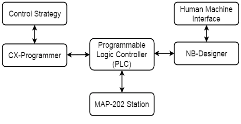
Figure 2.1: Project Overview
2.2 MAP 202 Handling System
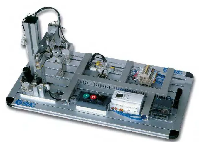
MAP is a series of products for simple PLC control and fault finding. MAP 202 is from the MAP 200 Handling system series. MAP 202 Station is a vacuum-held handling device with two shafts which moves a part from one position to another by holding it with a set of three vacuum pads. As shown as Figure 2.2, the dimension of this station is about 740x400x445mm and the weight is approximately around 20kg. As the air treatment unit, this station equip with filter with pressure regulator, pressure gauge, throttle, drain valve and also supply pneumatic pressure around 0.6MPa to actuate the actuator that using air pressure. (Technical Description MAP 202, 2015)
To make this station functional, a 100-240Vac or 24Vdc (60W) power source was supplied. For the current controller, there are keypads to start and stop push buttons. Besides that, it also has automatic-manual selector to choose whether to run this station on automatic mode or manual mode.
8
Figure 2.2: Layout of MAP 202
2.3 Programmable Logic Controller (PLC)
The National Electrical Manufacturing Association (NEMA) defines a PLC as a programmable logic controller is a digital electronic apparatus that has programmable memory to store instructions to implement specific functions. PLC also defines as a specialized electronic device based on one or more microprocessors that are used to control industrial machinery. The definitions state that PLCs are industrial computers designed to operate in the harsh physical and electrical noise environments present in production plants (James A Rehg, 2009). The functions of PLC are for logic, sequencing, timing, counting and arithmetic to control machines and processes. The role of the PLC is commonly regarded as the heart of the control system.
9
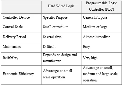
The PLC provides an easy way to reprogram the wiring rather than actually rewiring the control system. Table 2.1 shows the advantages of PLC against hard wired logic that used before PLC.
Table 2.1: Differentiation between Hard Wired Logic and PLC
Hard Wired Logic Programmable Logic Controller (PLC) Controlled Device Specific Purpose General Purpose
Control Scale Small or medium Medium or large
Delivery Period Several days Almost immediate
Maintenance Difficult Easy
Reliability Depends on design and
manufacture Very high
Economic Efficiency Advantage on small scale operation
Advantage on small, medium and large scale operation
The specific features of PLC:-
1. Has noise immune capabilities and more rugged 2. Easy to replace or add units of construction 3. Standard signal level and input output connection
4. Programming language using ladder diagram is easy to understand 5. Easy to program and reprogram
6. Low cost production equipment
2.3.1 Ladder Diagram Programming