DOI: 10.12928/TELKOMNIKA.v14i3.4056 807
Sensitivity Analysis and Comparison between 25 kW
Parabolic Dish System
Mohd Ruddin Ab Ghani*1, Liaw Geok P heng2, Chin Kim Gan3, Tole Sutikno4
1,2,3
Faculty of Electrical Enginering, Universiti Teknikal Malaysia Melaka (UTeM), 76100, Durian Tunggal, Melaka, Malaysia.
4
Department of Electrical Engineering, Faculty of Industrial Technology, Universitas Ahmad Dahlan (UAD), Jln Prof. Dr. Soepomo, Janturan, Yogyakarta 55164, Indonesia
*Corresponding author, email: [email protected]
Abstract
Dish-Stirling concentrating solar power systems is an efficient and reliable source of renewable energy. In this paper, the proposed model showed the idea of Parabolic Dish (PD) systems with control system model which vary the amount of working gas in the Stirling engine. The control systems were designed using Matlab /Simulink 2012a. Based on the developed linearized model, an improved temperature controller with transient droop characteristic and Mean Pressure Control (MPC) has been proposed. This temperature controller was effective in reducing the temperature and improving performance of the PD system. The overall performance of the system improved more than 78% in output power and energy. Besides, the system improved in term of sensitivity compared with the PD system without compensated. In addition, thermal losses decreased to 97.6% which is directly have significant improvement for the output efficiency to the system. The analysis shows that the PD system is feasible in term of technical but not economically feasible in the Malaysia environment.
Keywords: parabolic dish (PD) stirling concentrating solar power, control systems, linearized model, transient droop characteristic, mean pressure control (MPC)
Copyright © 2016 Universitas Ahmad Dahlan. All rights reserved.
1. Introduction
The primary control objective within the power conversion unit of a dish-stirling (DS) system is to maintain the heater temperature within a safe operating region. The temperature should be kept as high as possible to maximize the thermal efficiency of the Stirling engine, but should also not exceed the thermal rating of the heater material. The temperature is controlled by varying the working gas pressure, achieved by adding or removing working gas to/from the engine. Changing the pressure of the Stirling engine working gas changes the quantity of mass flow through the heater, thereby changing the amount of heat removed from the heater as shown in Figure 1 [1].
Figure 1. Dish Stirling Engine control system diagram [1]
2. Research Method
valves [8] and [9], where modulation techniques can be used to regulate the flow of gas through the valve [10].
Because the Stirling engine is a closed system, the supply and dump valves are closed in a steady state. Only when a change in operating point occurs does one of these valves open, such as the case when the irradiance increases, where the supply valve will open to increase the pressure. The solenoid valves are assumed to be pulse-width modulated (PWM) valves, where the valves are turned on and off successively, delivering mass in discrete packets [11] and [12].
The modulation frequencies of solenoid valves range from 20 Hz to 80 Hz, and the mass flow rate is proportional to the averaged spool position [13], where the “spool” is the magnetic piece of the solenoid valve that reacts to the voltage applied to the solenoid coils, and either opens or closes the valve. The solenoid valves are modeled as a first order system, given by [1] and [2]:
����(�) �(�) =
��
1+��� (1)
Where gASV is the mass flow in the solenoid valve (kg/s), C is the commanded mass flow rate, s
is the Laplace transform variable, and Kv and Tv are the gain and time constant of the valve, respectively. The pressure of the storage tanks are assumed to be constant, and, according to [2], the mass flow through the open valve can be approximated by:
gA = px���2
4 (2)
Where ρ is the gas density (kg/m3), Dp is the pipe diameter (m), and x is given by [1] and [2].
x =�2��(���−�)
��� (3)
Where pst is the high pressure storage tank pressure (Pa), f is the friction factor, and L is the length of the pipe (m). Thus, assuming the minimum working gas pressure for p, the mass flow rate limit is a function of the pipe dimensions. The pressure of the high pressure gas storage tank and the pipe dimensions connecting the gas storage tank to the engine play a major part in the control system performance [1] and [2].
2.2. Temperature Control System
Figure 2. Pressure Control System Connection to Stirling Engine [1]
3. Results and Discussion
3.1. Sensitivity Comparison Study
In order to validate the simulation results in this study, the results were compared with result from The Solar Dish-Stirling System Model [14] based on performance for five main components, the heater temperature, thermal losses, stirling engine gross power output, net output power, energy, capacity factor and LCOE. Nevertheless, the concentrator, receiver parameters as well as the daily solar irradiance, used in this study (25 kW PD system model with compensator system) and 25 kW PD system model without compensator system were similar. Therefore, the comparison of the result between this modelling with The Solar Dish-Stirling system Model is necessary.
3.2. Heater Temperature
High temperature achieved at a focal point is issued as a heat source for a Stirling engine. The Stirling engine is capable of operating at high efficiency and releases no emission, making it highly compatible with the solar thermal power technology. Unfortunately, the often random and uncontrollable natures of solar irradiance possess a challenge in the control of the PD system. Therefore, the PD system operates most often in controlled temperature region in order to maximize the efficiency of the Stirling engine.
Besides that, controlling the amount of heat in the heater/receiver is critical for a Stirling engine. The temperature of the heater should be maintained as high as possible, for high efficiency, while not exceeding the thermal limits of the heater material. The temperature of the heater is prevented from exceeding 1000K to prevent damage to the heater material and the efficiency of the output performance.
Figure 3 shows the comparison between heater temperature with and without the compensator. Heater temperature without compensator was over the range of threshold and this would damage the heater material, and would also produce many losses, thus, causing low output power and energy. According to the results, the heater temperature with compensator was able to control the heater temperature in the range of threshold which is in between of 1000K by varying the working gas pressure which is effectively changing the heat exchange rate between the Stirling engine and heater.
3.3. Thermal Losses and Srirling Engine Gross Power Output
The temperature increases more than TSET, when the irradiance is high enough, the mean pressure from the TCS increases to regulate an increasing temperature on the heater. In this condition, the receiver temperature is to be controlled. The
temperature ΔTMAX shows that the amount of the heater temperature can be increased above the temperature set point and are still regulated by the PCS.
Temperature increases in the receiver during the high irradiance. The heat absorbed by the engine increases by supplying working gas from high pressure storage tank to the engine, simultaneously increasing the Pset and opening the solenoid supply valve. However, a decrease in irradiance then decrease the temperature, thus the working gas has to remove from the engine through the solenoid dump valve.
When temperature of the heater exceeds TSET +
ΔTMAX, a maximum pressure occurs inside the engine and, therefore. Is unable to be increased further to regulate the temperature of the heater. The temperature of the receiver is prevented from exceeding the range of threshold to prevent damage to the receiver material. However, to maintain the heater temperature within a narrow range the pressure is being varied. The maximum allowable engine pressure Pmax is practically high enough that the heater can be maintained at a safe temperature even during high irradiance.
From a thermodynamic point of view, the Stirling cycle efficiency increases with an increase in maximum temperature. But the plant efficiency and output decrease at higher heater gas temperature. It is because of increased heat transfer losses mainly radiation losses at high temperature. Therefore, the thermal losses are directly proportional to heater temperature and net output power is inversely proportional to thermal losses.
Figure 3. The Comparison between Heater Temperature with and Without the Compensator
As the 25 kW PD system model with compensator system, therefore, the total thermal losses obtained for this model were low compared to the 25 kW PD system model without compensator system which was 447496W and 881567W respectively whereas the total Stirling engine gross output power high compared to the 25 kW PD system model without compensator system which were 18013 W and 11209 respectively. Therefore, the Stirling engine gross output power increased around 61%, and the thermal losses decreased around 97.8% after installing the temperature control system. According to the Figure 4 and 5, the thermal losses show a very significant decrease and increase in Striling engine gross output power after installing the control system. The temperature was controlled by varying the working gas pressure inside the engine. To increase the pressure, the high pressure storage tank was able to supply gas into the engine. Heater surface temperature increased when high irradiance existed, therefore high pressure storage tank supplied the working gas to the engine to regulate the temperature of the heater. Hence, increasing the power output of the system.
Figure 5. The Comparison between Gross Power Stirling Engine with and Without the Compensator
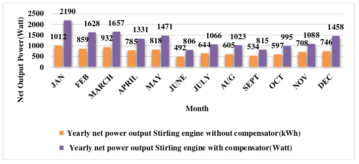
3.4. Annual Output Power, Annual Energy and LCOE
Figure 6 and 7 show the annual output power and energy obtained from 25 kW PD system modelling with compensator and the 25 kW PD system modelling with compensator respectively.
As the 25 kW PD system model with compensator system, therefore, the total annual output power and energy obtained for this model were high compared to the 25 kW PD system model without compensator system which were 15528W, 8732W, and 14923kWh, 8383kWh respectively. Therefore, the output power and energy increased around 78% after installing the temperature control system.
Figure 6. The Comparison between Yearly Net Power Output with and without the Compensator
Apart from the solar irradiance, this study has shown that the design such as the mean pressure control with proportional controller design was the significant criteria that affect the output of PD system.
However, the sensitivity analysis of LCOE which has been carried out to study the effect of uncertainties in the input parameters such as capital cost, O & M cost, capacity factor, discount rate and PD system life time on the LCOE showed a decrease of 45% of LCOE after implementing temperature control system. Table 2 shows the sensitivity analysis of LCOE, capacity factor, and energy performance between PD system with and without compensator.
1012 859 932 785 818
Yearly net power output Stirling engine without compensator(kWh)
Figure 7. The Comparison Between Yearly Energy with and Without the Compensator
In sensitivity analysis, it is also important to predict the trend of LCOE with change in input parameters. The LCOE increased with an increase in capital cost, O &M cost and discount rate. The effect of capital cost and discount rate on LCOE was more than the O & M cost. The LCOE decreased with an increase in capacity factor and the PD system life. At lower PD system capacity factor, the LCOE was very high due to lower annual power generation and the rate decreased in LCOE was less costly than the rate of increase in PD life and capacity factor. The LCOE depended mainly on the capital cost, capacity factor and discount rate.
Table 2. Sensitivity Analysis of LCOE, Capacity Factor, and Energy Performance between PD System with and without Compensator
Criteria Before implement temperature control system After implement temperature control system
Total Energy 8383 kWh 14923 kWh
Capacity Factor 3.83% 6.774%
LCOE RM 36.0393 RM 20.2499
4. Conclusion
Dish-Stirling (DS) solar-thermal generation system is a type of renewable energy technology. Stirling engine is capable of operating at high efficiency and releases no emissions. Unfortunately, the often random and uncontrollable nature of solar irradiance makes the control of the heater temperature and output efficiency of the Parabolic Dish system is the most challenging. Hence, a proper appropriate control system design and operations of the system are called for.
The purpose of this research is to design control system to maintain the heater temperature within a safe operating region for reduced losses to improve the output efficiency of the system. The temperature should be kept as high as possible to maximize the thermal efficiency of the Stirling engine, but should not also exceed the thermal rating of the heater material. The temperature is controlled by varying the working gas pressure, achieved by adding or removing working gas to/from the engine. In simulation studies, the design of the control system to the system was modelled by Matlab Simulink [14].
It is essential to know the efficiency of the control system to the PD system, sensitivity comparison between compensated and without compensated system, performance and feasibility analysis of CSP especially for PD system in the Malaysia environment. Analyze the performance and the feasibility in term of cost, benefits as well as the technical and economic feasibility of PD development in Malaysia.
From this paper, it can be said that the 25 kW PD system in the Malaysia environment is technically feasible, but not economically feasible. The simulation results have shown the ways that PD system successfully achieves its performance. Ample resources exist in Malaysia
971 824 895 754 786
Yearly energy Stirling engine without compensator(kWh)
References
[1] Howard DF, Harley RG, Liang J, Venayagamoorthy GK. Effects of variable solar irradiance on the
reactive power compensation for large solar farm. In Bulk Power System Dynamics and Control
(iREP)-VIII iREP Symposium. 2010: 1-8.
[2] Li Y. Dish-Stirling solar power plants: modeling, analysis, and control of receiver Temperature.
Sustainable Energy, IEEE Transactions on. 2014; 5(2): 398-407.
[3] Powell MA, Rawlinson K. Performance mapping of the STM4-120 kinematic Stirling engine using a
statistical design of experiments method. Sandia National Labs. Albuquerque, NM, United States. No:
SAND--92-2869C, CONF-930804-6. 1992
[4] SAIC (Science Applications International Corporation). Facet Development for a Faceted
Stretched-Membrane Dish bySAIC. Albuquerque, NM: Sandia National Laboratories. Report number:
SAND91-7008. 1991.
[5] Pheng LG, Affandi R, Ab Ghani MR, Gan CK, Jano Z, Sutikno T. A review of Parabolic Dish-Stirling Engine System based on concentrating solar power. TELKOMNIKA (Telecommunication Computing
Electronics and Control). 2014; 12(4): 1142-1152.
[6] Günther M, Shahbazfar R, Fend T, Hamdan M. Solar Dish Technology. Schlaich Bergermann und Partner: Euro Dish Stirling System Description. A new decentralized Solar Power Technology. [7] Keck T, Schie, W. EnviroDish and EuroDish System and Status. In Proceedings of ISES Solar World
Congress. 2003.
[8] Lovegrove K, Stein W. Concentrating solar power technology: principles, developments and applications. Elsevier. 2012.
[9] Brehm P. Concentrating Solar Power Systems Dish Innovation. VP, Business Development &
Government Relations. 2009.
[10] Kaneff S. The White Cliffs Project Overview for the period 1979–89. NSW Office of Energy. Sydney, Australia. 1991.
[11] Lovegrove K, Burgess G, Pye J. A new 500m 2 paraboloidal dish solar concentrator. Solar
Energy. 2011; 85(4): 620-626.
[12] Buck R, Heller P, Koch H. Receiver development for a Dish-Brayton system. American Society of Mechanical Engineers. New York, NY (United States). No: CONF-9603117. 1996.
![Figure 1. Dish Stirling Engine control system diagram [1]](https://thumb-ap.123doks.com/thumbv2/123dok/256265.504987/1.595.174.429.577.672/figure-dish-stirling-engine-control-diagram.webp)
![Figure 2. Pressure Control System Connection to Stirling Engine [1]](https://thumb-ap.123doks.com/thumbv2/123dok/256265.504987/3.595.137.462.87.264/figure-pressure-control-system-connection-to-stirling-engine.webp)
![Table 1. The Pressure Commanded by the TCS [1-3]](https://thumb-ap.123doks.com/thumbv2/123dok/256265.504987/4.595.91.512.92.634/table-pressure-commanded-tcs.webp)