DOI: 10.12928/TELKOMNIKA.v14i1.2958 404
Photovoltaic Array Maximum Power Point Tracking
Based on Improved Method
Jia Cunliang*1, Wang Yanxiong2, Wang Zerong3
1,2School of Information and Electrical Engineering, University of Mining and Technology,
China Xuzhou, 0516-83890717
3
No.716 Research Institute Lianyungang, China, 18036678556 *Corresponding author, e-mail: [email protected]
Abstract
At present, a good deal of methods for the Maximum Power Point Tracking (MPPT) has been used in engineering applications. However, Matlab simulation proved that they were difficult to harmonize the stability and speed ability of system. In addition, in order to maximize the use of PV panels ‘power, the paper focused on aneonatalalgorithm for Maximum Power Point Tracking (MPPT). Based on the algorithm, this paper designed an improved and feasible variable step perturbation and observation method which well alleviated the conflict that the maximum power point tracking could not take into account the stability and speed of response efficiently.
Keywords: PV power generation, MPPT, Variable step perturbation and observation method
Copyright © 2016 Universitas Ahmad Dahlan. All rights reserved.
1. Introduction
In photovoltaic power generation systems, actual output power of often depends on light intensity, battery temperature and load impedance [1]. In the three factors of output characteristic of the PV cells, light and temperature is external environment which is unable to control. Therefore, adjusting the impedance value of load is the only choice to make PV cells output maximum power in the practical work, meanwhile, this is the essence of photovoltaic array maximum power point tracking. At present, the MPPT methods used by researchers at home and abroad include: constant-voltage method, perturbation and observation method, synovial control, incremental conductance method, fuzzy control and neural network prediction method [2-4]. Perturbation and observation is the most commonly used method in practice for its simplicity and ease of implementation [5]. However, it suffers from the slow tracking speed at small duty cycle step and fluctuates when subjected with large duty step, which results in higher losses under dynamic weather to which the photovoltaic PVcells exposed [6]. This paper focused on an improved and feasible variable step perturbation and observation method here.
PV cells are recognized for having non-linear characteristics. At one point, which is known as the maximum power point (MPP), the cells are capable to operate at maximum efficiency and give the maximum output [7-10]. According to the photovoltaic cells equivalent circuit model [11], two typical output characteristic curves of PV cells can be determined under a certain temperature and illumination parameters: output current-output voltage (I-V) characteristic curve and output power-output voltage (P-V) characteristic curve are shown as Figure 1.
(a) I - V characteristic curve (b) P - V characteristic curve
In the Figure 1, Isc and Voc is short circuit current and open circuit voltage of PV cells respectively. MPP (Maximum Power Point) is the working point of maximum output power of photovoltaic panels, then the Vm is voltage and Im is current of MPP. Connecting PV cells terminals to load resistance, its external characteristic curve is the origin of the dotted line in Figure 1(a). As the load resistance is increasing from 0 gradually, the output voltage and output power of the PV cells are also increased slowly from 0; When the load resistance increases to Rm in Figure 1(a), the output power of photovoltaic panels increases topeak, namely in the MPP, and Pm = ImVm; Continuing to increase the load resistance, the output voltage of PV cells continues to increase, but its output power begins to decrease.
Figure 1(b) is the P - V characteristic curve about the change of the relationship between load changes of PV cells and output voltage, and the MPP point corresponds to MPP point in the Figure 1(a). When the load resistance decreases from infinity to Rm, P - V characteristic curve is right side part of the MPP point in Figure 1(b) accordingly; when the load resistance over Rm continues to scale down, corresponding P - V characteristic curve is the left side part of the MPP point in Figure 1(b).
2. The Proposed Method
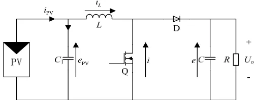
In photovoltaic power generation systems, maximum power point tracking (MPPT) of PV cells is achieved by DC/DC converter usually. To be in the implementation principle, the total circuit composed of DC/DC converter and load is regarded as the system equivalent load whose size is a certain function of duty-cycle D of the working DC/DC converter. Thus, the output power of PV cells can be changed by adjusting the duty-cycle D simply, and then MPPT function is implemented. Boost converter circuit diagram is shown in Figure 2.
PV
Figure 2. Diagram of boost converter circuit in PV system
In Figure 2, assuming that Q is an ideal power switch can obtain two kinds of state equation of Q in each cycle according to the dynamic circuit analysis method.
Q is conducted:
In accordance with the state-space averaging method, (4) is the state-space equations:
PV 1 PV 1 T
is a function of D, therefore, the system working point will be changed with the variation of duty-ratio D while the Boost converter in Figure 3 is working. When dP/dePV=0, the function of MPPT
is realized [12].
3. Research Method
3.1. MPPT Fixed Step Algorithm
In this paper, the PV cell is connected to a DC bus through the Boost converter. In order to realize MPPT, the equivalent load impedance of the photovoltaic power generation system can be changed by adjusting the duty-ratio (D) of the Boost converter and making it the same as the power source internal resistance. Although a lot of the MPPT methods have been used at home and abroad, perturbation and observation method is commonly adopted in the engineering practice to write control programs and perturbation step is usually a fixed value because of the limitation of processing speed of current microprocessor.
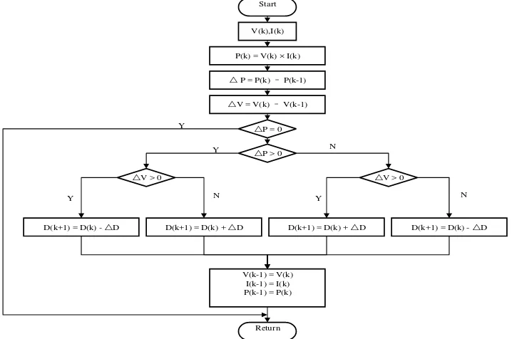
Flow graph of fixed step size perturbation and observation method is Figure 3. I (k), V (k) and P (k), respectively, is output current, output voltage and output power of photovoltaic power generation system in the kth time sampling. ᇞP is the system power difference between before and after sampling, ᇞV is the output voltage of PV cells difference between before and after sampling, D(k) is duty-cycle of drive signal of power electronic device and ᇞD is the fixed variational step of D(k).
Start
The simulation results can be found in the last section, when ᇞD is larger, the response speed of system under illumination change is rapid, but the output power of PV cells has a strong shock near the maximum power point. When ᇞD begin to decrease, the oscillation amplitude is decreased obviously; however, the system tracks illumination change at a slower pace. It is visible that fixed step algorithm is difficult to coordinate between stability and rapidity for MPPT in the system.
3.2. MPPT Improved Variable Step Algorithm
In order to overcome the shortage of the former perturbation and observation method, this paper improved algorithm based on the fixed step MPPT simulation experiments. With the change of output voltage (V), the change rule of output power of PV cells (P) can be summed up in Figure 1(b). As shown in Figure 4, M1, M2, M3 and M4 are obtained from the P - V characteristic curve in Figure 1(b).
Figure 4. Output characteristic curve tangent of PV module
By comparison, the slope relationship among M1, M2, M3 and M4 can be obtained in Figure 4.
M 2 M 2 M 1 M 1 M 3 M 3
M 2 M 2 M 1 M1 M 4 M 4
d d d d d d
d d d d d d
P V P V P V
P V P V P V
(5)
Visibly, slope of P - V characteristic curve is minimum only in the maximum power point M2 (dPM 2 dVM 2 =0), making use of the relationship of ᇞP/ᇞV on the curve and output power
P to adjust step value every time in perturbation method, namely, the slope and disturbance step have positive correlation, then the system search of stability and rapidity can be coordinated. Therefore, ᇞD(k) in the moment of k is as follows:
( ) ( ) ( 1)
( ) ( ) ( 1)
( ) ( ) ( ) P k P k P k
V k V k V k
D k P k V k D
(6)
ᇞV(k) and ᇞP(k), respectively, is output voltage variation and output power variation of PV cells, during the moment of (k - 1) to k due to change of duty ratio. ᇞD is the fixed variation step of the previous perturbation and observation method. Consequently, ᇞD(k) substitutes for ᇞD in Figure 3 according to the formula (6) in the control flow chart of improved algorithm.
near the maximum power point. The Figure 4 shows that ᇞP(k)/ᇞV(k) has a positive and a negative on both sides of MPP, the working point of PV cells is inversed alternately between left and right sides of MPP under the perturbation method. Something can be obtained when the working point is change:
( 1) ( ) 0 ( 1) ( ) ( 1) ( )
0 ( 1) ( )
P k P k
S
V k V k
P k P k
S
V k V k
(7)
In formula (7), S is a positive that shows the working point of PV cells did not reach the MPP, ᇞD should choose a large step to track the external environment variation rapidly. The working point of PV cells jumps from one side to the other side of MPP when S inverses from a positive to a negative. That is to say, the working point of PV cell is near the MPP and ᇞD should choose a small step to reduce the power oscillation of the system near the MPP. According to the above step conversion method the second improvement of algorithm has been completed. Judging whether S is a positive or not before judging ᇞP=0 in the flow chart of figure 3 to choose the best ᇞD.
4. Results and Discussion
As shown in Figure 5, set up the maximum power point tracking (MPPT) simulation model of photovoltaic power generation system based on Matlab/Simulink software environment and make use of the main circuit of Boost converter designed in section 2.
Figure 5. Maximum power point tracking simulation model
4.1. Simulation of Fixed Step Perturbation and Observation Method
0 0.1 0.2 0.3 0.4 0.5 0.6 0
200 400 600 800 1000
t/(s) (a) The output power curve of photovoltaic panels
0 0.1 0.2 0.3 0.4 0.5 0.6 0
0.1 0.2 0.3 0.4 0.5
t/(s) (b) The change of duty ratio
Figure 6. Simulation curve of fixed step size perturbation and observation method (ᇞD =0.002)
Figure above is the simulation waveform when ᇞD=0.002. The initial illumination is 1000W/m2 but it decreases to 900W/m2 when t=0.35s. Then it is back to 1000W/m2 when t=0.45s. Figure 6(a) shows that the output power of photovoltaic panels is maximum at t=0.03s after the running of Boost converter and the maximum power tracking is achieved. If the light intensity changes suddenly, Boost converter can quickly track the illumination change and continue to make photovoltaic panel’s output maximum power. But it is also can be seen from the figure, the maximum output power of photovoltaic panels will shock on a small scale whose amplitude closes to 20W due to the large step length, which cannot meet the requirements obviously. In order to reduce the concussion ᇞD should be reduced, for example, the oscillation amplitude of the stable output of the photovoltaic panels is controlled well as ᇞD=0.0002 and the requirements of stability is meet. However, the tracking speed is too slow to adapt to the weather whose illumination is changed frequently.
4.2. Simulation of Improved Variable Step Perturbation and Observation Method
Figure 7 is MPPT simulation curve of the improved variable step perturbation and observation method. The larger ᇞD and the smaller ᇞD in the simulation program is 0.002 and 0.0002 respectively. It is shown in the figure that the maximum power output of photovoltaic panels was achieved about 0.05s with this algorithm. Boost converter could quickly track the change of light intensity as t=0.3s and t=0.5s and continued to make photovoltaic panels output the maximum power. There is a nice stability in both cases.
(a) The output power curve of photovoltaic panels
(b) The change of duty ratio
5. Conclusion
Simulation experiments shows that the improved variable step perturbation and observation method overcomes the drawback of the two previous perturbation and observation methods well. In addition, it alleviated the conflict that the maximum power tracking cannot take into account the accuracy of steady state and speed of response efficiently.
References
[1] Qian Nianshu, Liu Kuo, Guo Jianye. Research of Photovoltaic cell modeling and its output characteristic. Journal of power. 2012; 10(5): 78-82.
[2] Ahmed EM, Shoyama M. Single variable based variable step size maximum power point tracker for
stand-alone battery storage PV systems. IEEE International Conference on Industrial Technology.
2011; 32(21): 210-216.
[3] Barchowsky A, Parvin JP, Reed GF, et al. A comparative study of MPPT methods for distributed
photovoltaic generation. IEEE PES Innovative Smart Grid Technologies (ISGT). 2012: 1-7.
[4] Parlak KS, Can H. A new MPPT method for PV array system under partially shaded conditions. 2012
3rd IEEE International Symposium on Power Electronics for Distributed Generation Systems (PEDG). 2012: 437-441.
[5] Jusoh A, Sutikno T, Guan TK, Mekhilef A. A Review on Favorable Maximum Power Point Tracking
Systems in Solar Energy Application. TELKOMNIKA Telecommunication, Computing, Electronics and
Control. 2014; 12(1): 6-22.
[6] Awang Bin Jusoh, Omer Jamal Eldin Ibrahim Mohammed, ToleSutikno. Variable Step Size Perturb
and Observe MPPT for PV Solar Applications. TELKOMNIKA Telecommunication, Computing,
Electronics and Control. 2015; 13(1): 1-12.
[7] Emilio M, Giovanni P, Giovanni S. Two-steps algorithm improving the P&O steady state MPPT efficiency. Applied Energy. 2014; 113: 414-421.
[8] Jancarle LS, Fernando A, Anis C, Cícero CA. Maximum power point tracker for PV systems using a
high performance boost converter. Solar Energy. 2006; 80(7): 772-778.
[9] Ali AG, Seyed MS, Asma S. A high performance maximum power point tracker for PV systems.
International Journal of Electrical Power & Energy Systems. 2013; 53: 237-243.
[10] Pallavee B, RK Nema. Maximum power point tracking control techniques: State of art in PV
application. Renewable and Sustainable Energy Reviews. 2013; 23: 224-241.
[11] Fu Wang, Zhou Lin, GuoKe. Photovoltaic cell engineering in mathematical model research. Journal of
Electrotechnics. 2011; 8(10): 211-216.