UNIVERSITY OF BIRMINGHAM
DEPARTMENT OF ELECTRONIC, ELECTRICAL AND
SYSTEMS ENGINEERING
MSc in Electrical Power Systems
Power System Stability and Control
Tutorial Questions
Q1
The nonlinear dynamic equation for a pendulum is given by
sin( )
ml mg kl (1)
Where
0
l is the length of the pendulum;
0
m is the mass;
0
k is a friction parameter;
is the angle subtended by the rod and the vertical axis through the pivot point, see Figure 1.
Figure 1 The pendulum for Q1
(a) Choose appropriate state variables and write down the state equations
(b) Find all equilibria of the system
(c) Linearize the system around the equilibrium points, and determine if the system
Q2
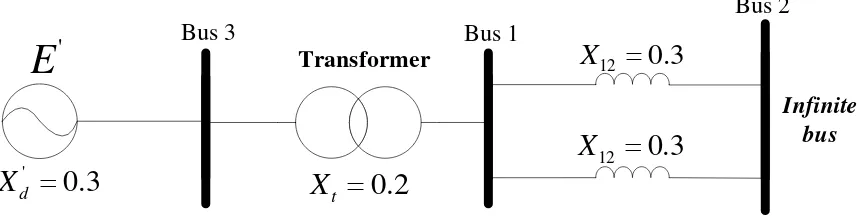
Consider a 60-Hz synchronous generator having inertia constant H=9.94 MJ/MVA and a
transient reactanceXd' 0.3 per unit is connected to an infinite bus through a purely reactive
circuit as shown in Figure. 2 (The generator is represented by classical model). All
reactances marked on the diagram are calculated on a common system base. At steady-state,
the generator is delivering 0.6 per unit of active power with 0.8 power factor lagging to the
infinite bus. The infinite bus has a voltage magnitude of 1.0 per unit and a voltage angle of
zero.
Assume the per unit damping coefficientKD 52.0248(in per unit torque/per unit speed).
Consider a small disturbance of 10o0.1745 rad.
Please calculate the motion of rotor angle as function of time (assuming constant mechanical
torque input).
Figure 2 Single line diagram for Q2
Q3
Consider the same generator in Q2 operating in the same steady-state condition. If the
disturbance now is on the input mechanical torque, which is increased by a small amount of
0.2
m
T