i
UNIVERSITI TEKNIKAL MALAYSIA MELAKA
INFLUENCE OF SUSPENSION PREPARATION CONDITION
AND MEDIUM MICROSTRUCTURE AND PHASE OF
ELECTROPHORETIC DEPOSITED POLY(VINYLIDENE
FLUORIDE) FILMS
This report submitted in accordance with requirement of the Universiti Teknikal Malaysia Melaka (UTeM) for the Bachelor Degree of Manufacturing Engineering
(Engineering Materials) (Hons.)
by
NURSYAFIKA BINTI ROHIZAT B051110355
901130-01-6122
i
ABSTRAK
ii
ABSTRACT
iii
DEDICATION
I dedicate this report to my frist and second supervisor, Dr. Muhammad Zaimi bin Zainal Abidin and Dr. Lau Kok Tee, thank you for being a guider during this final year project. Thank you for your cooperation and help in the success of this report. Thanks also to my parents for being a pillar of strength for me when I was weak and also to my friends, thank you for not throwing me away when I disappoint you. Thank you for loving me.
iv
ACKNOWLEDGEMENT
First of all, I am grateful to God for the opportunity to prepare this final year project report. Special appreciation to my first supervisor, Dr. Muhammad Zaimi bin Zainal Abidin for his supervision and constant support. His invaluable help of constructive comments and suggestions throughout the report. Not forgotten, my appreciation to my second supervisor, Dr. Lau Kok Tee for his support and knowledge regarding this topic.
I would like to thank to all the assistance engineers that assist in identifying equipment that will be used in the laboratory and I am indebted to my final year project examiners, Associate Prof. Dr. Zulkifli bin Mohd Rosli and Dr. Zurina binti Shamsudin for being my correctors. Therefore, I consider myself as a very lucky individual as I was provided with an opportunity to be a part of this project. I am also grateful for having a chance to meet so many wonderful people and professionals who lead me through this final year project.
v
TABLE OF CONTENTS
Abstrak i
Abstract ii
Dedication iii
Acknowledgement iv
Table of Contents viii
List of Tables ix
List of Figures viii
List Abbreviations, Symbols And Nomenclatures xii
CHAPTER 1: INTRODUCTION
1.0 Introduction 1
1.1 History and Background 2
1.2 Problem Statement 6
1.3 Objectives 7
1.4 Scope 7
CHAPTER 2: LITERATURE REVIEW
2.0 Introduction 8
vi
2.2 Deposition of PVDF 12
2.3 Definition of Agglomeration 14
2.3.1 Attributes and Characterization of Agglomeration 16
2.4 Dissolution 17
2.4.1 Factors of dissolution 17
2.5 Sedimentation Test 18
2.6 EPD (Electrophoresis Deposition) 19
2.6.1 Mechanism of Electrophoretic Deposition EPD 21
2.6.1.1 Particles Accumulation 21
2.6.1.2 Electrostatic Force 21
2.6.1.3 Salting Out 22
2.6.1.4 Neutralization 22
2.6.1.4 Squeezing Out 22
2.7 Electro-Plating 23
2.8 Vapour Deposition 24
2.8.1 Evaporation 24
2.8.2 Transportation 25
2.8.3 Reaction 25
2.8.4 Deposition 25
vii CHAPTER 3: METHODOLOGY
3.0 Introduction 28
3.1 Formulation of PVDF Suspension 30
3.2 Electrophoretic Deposition of PVDF Film 34
3.3 Surface Microstructure, Thickness Measurement and Elemental Analysis 36
CHAPTER 4: RESULTS AND DICUSSION
4.0 Introduction 39
4.1 Sedimentation test 40
4.2 Surface Microstructures of PVDF Films 42
4.3 FTIR (Fourier transform infrared spectroscopy) 51
CHAPTER 5: CONCLUSION
5.0 Introduction 53
5.1 Conclusion 54
5.2 Recommendations 55
REFERENCES 56
viii
LIST OF TABLES
Table 1.1 Discovery of Piezoelectric Materials and Their 5 Mechanisms or Applications (Katzir, 2012)
Table 2.1 General Properties of PVDF (Frank, 2014) 10 Table 2.2 Comparison of Smart Materials (Leo, 2002) 11 Table 2.3 Comparison Piezoelectric Constants between PZT-4, 11
BaTiO3, PVDF, and Quartz (Leo, 2002)
Table 2.4 Comparison Between EPD, Electro-Plating and Vapour 26 Deposition (Grainger and Blunt, 1998)
Table 3.1 Range of Times and Temperatures (Kolev, 2012) 33
Table 4.1 Average thickness of PVDF films prepared in MEK 45 based suspensions
Table 4.2 Average thickness of PVDF films prepared in DMF 48 based suspensions (coverage area only)
ix
LIST OF FIGURES
Figure 1.1 PZT (Lunes, 2010) and BaTiO3 structures 2
(Ersin, 1999)
Figure 2.1 Crystal Structure pf PVDF 9
Figure 2.2 SEM result (Razi, 2014) 13
Figure 2.3 FTIR Spectra of β-PVDF in Perpendicular Stress 13 Deformation (Mano, 2001.
Figure 2.4 Linkage Between Material Properties, Process 14 Parameters, Transformations and Product Attributes
in A Binder Agglomeration Process. (Mort, 2005)
Figure 2.5 Agglomeration Nucleation Mechanisms: (a) Distribution, 15 and (b) Immersion. Granule Properties Typically Depend
on the Mode of Nucleation and Growth. (Morth, 2005)
Figure 2.6 Mechanism of sedimentation process 18
Figure 2.7 Schematic of Electrophoretic Deposition Setup 20 (Razi, 2014).
Figure 2.8 Electroplating Process (Anonymous, 2011). 23
Figure 3.1 Flow Chart of the Experiment 29
x Figure 3.4 Cross Section of PVDF Layer on the ITO Glass 35
Substrate
Figure 3.5 UV-Spectroscopy. 36
Figure 3.6 Fourier Transform Infrared Spectroscopy 37
Figure 3.7 Mini Sputter Coater. 38
Figure 3.7 Scanning Electron Microscope. 38
Figure 4.1 Sedimentation results of PVDF particle in MEK based 40 suspensions
Figure 4.2 Sedimentation process of PVDF prepared in DMF based 41 suspensions
Figure 4.3 UV-vis results of PVDF film prepared in MEK based 42 suspensions
Figure 4.4 a) SEM results of PVDF film surface, while b), c) and 43 d) cross section of deposited sample at 53⁰C, 8 hour stirring
condition in MEK based suspension
Figure 4.5 SEM results of PVDF film surface and cross section 44 of deposited sample at 62⁰C, 2 hour stirring condition in
MEK based suspension
Figure 4.6 SEM results of PVDF film surface and cross section 44 of deposited sample at 64⁰C, 8 hour stirring condition in
MEK based suspension
xi Figure 4.8 SEM results of PVDF film surface and cross section 46
of deposited sample at 80⁰C, 8 hour stirring condition in DMF based suspension
Figure 4.9 SEM results of PVDF film surface and cross section 46 of deposited sample at 120⁰C, 2 hour stirring condition in
DMF based suspension
Figure 4.10 SEM results of PVDF film surface and cross section of 47 deposited sample at 120⁰C, 8 hour stirring condition in
DMF based suspension
Figure 4.11 EDS point analysis of PVDF film prepared using 49 120⁰C, 2 hour stirring conditions
Figure 4.12 EDS point analysis of PVDF film prepared using 49 120⁰C, 8 hour stirring conditions
Figure 4.13 FTIR absorption bands of PVDF film prepared in 51 MEK based suspensions
xii
EDS - Energy Dispersive X-ray Spectroscopy EPD - Electrophoresis Deposition
xiii PVD - Physical Vapour Deposition
PVDF TeFE - PVDF Tetrafluoroethylene PVDF TrFE - PVDF Trifluoroethylene PVDF - Polyvinylidene Fluoride PZT - Lead Zirconate Titanate SEM - Scanning Electron Microscopy
Ti - Titanium
U.S - United State UV - Ultraviolet
1
CHAPTER 1
INTRODUCTION
1.0 Introduction
2
1.1 History and Background
When a piezoelectric substance is deformed, electric potential is generated. It is called piezoelectric effect. It was demonstrated by the brothers Pierre Curie and Jacques Curie in 1880 (Manbachi et al., 2011). Certain materials can generate a voltage when placed under stress, such as quartz, salt and sugar. These materials had crystal structures with asymmetric dipole moments that would respond to mechanical pressure (Morgan Advance Materials, 2009).
The crystalline structure produce a voltage proportional to the applied mechanical pressure when the crystals are exhibiting direct piezoelectric effect, which is electricity generated from applied stress. Vise-versa, the material exhibits the converse piezoelectric effect, a stress is generated in response to applied electric field (Jacques and Currie, 1881).
In 1945, ferroelectric ceramics were used as capacitor materials, because of its high dielectric strength. First ceramic to be discovered is quartz, followed by BaTiO3
(Barium Titanate) and then PZT (Lead Zirconate Titanate). The ceramics are also exhibiting high piezoelectric constant. However, they have several disadvantages, which are high melting point and low flexibility. Besides, PZT contains toxic lead element.
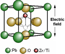
3 Figure 1.1 shows the crystal structures of BaTiO3 and Pb (Zr, Ti)O3. PZT consists of
one part of Pb (Lead), one part of Zr (Zirconia) and Ti (Titanium) and three parts of and O (Oxygen). Although PZT has higher permittivity and better crystal structures as piezoelectric applications than BaTiO3, the PZT is toxic. For BaTiO3, it consists of
one part of the Ba (Barium), one part of Ti and three parts of O. They still cannot fulfill the mechanical flexibility requirement of piezoelectric applications.
Then, new piezoceramic families and several types of piezoceramic signal filters were developed such as television, radio and communications equipments were created (Piezo Systems, Inc. 1994). The commercial success of the Japanese efforts has attracted the attention of the industry in many other nations and spurred a new effort to develop successful piezoceramic products in 1980.
In 1969, Kawai has found a strong piezoelectricity in PVDF (Polyvinylidene Fluoride) and it used as an alternative candidate to PZT and BaTiO3 (Kawai and
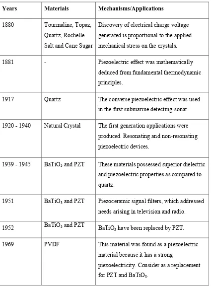
5 Table 1.1: Discovery of piezoelectric materials and their mechanisms or applications (Katzir, 2012).
Years Materials Mechanisms/Applications 1880 Tourmaline, Topaz,
Quartz, Rochelle Salt and Cane Sugar
Discovery of electrical charge voltage generated is proportional to the applied mechanical stress on the crystals.
1881 - Piezoelectric effect was mathematically
deduced from fundamental thermodynamic principles.
1917 Quartz The converse piezoelectric effect was used in the first submarine detecting-sonar. 1920 - 1940 Natural Crystal The first generation applications were
produced. Resonating and non-resonating piezoelectric devices.
1939 - 1945 BaTiO3 and PZT These materials possessed superior dielectric
and piezoelectric properties as compared to quartz.
1951 BaTiO3 and PZT Piezoceramic signal filters, which addressed
needs arising in television and radio.
1952 BaTiO3 and PZT BaTiO
3 have been replaced by PZT.
1969 PVDF This material was found as a piezoelectric material because it has a strong
6
1.2 Problem Statement
7
1.3 Objectives
In order to synthesize crack-free PVDF thick film, the current study embarks on the following objectives:
1. To characterize PVDF suspension prepared by different suspension formulations, processing temperatures and times.
2. To characterize the surface morphology, cross-sectional microstructure and phase composition of PVDF film electrophoretic deposited using the PVDF suspensions stated in objective 1.
1.4 Scopes
In this research, PVDF film will be deposited by EPD method using different PVDF suspension formulation, as well as suspension processing temperatures and times.
8
CHAPTER 2
LITERATURE REVIEW
2.0 Introduction
This chapter is about the properties of the PVDF, which used as piezoelectric components. Beside that, the methods and mechanisms involved also cited in this chapter.
9
2.1 General Material Properties of PVDF
PVDF crystal structures consist of Fluorine, Carbon and Hydrogen elements (refer Figure 2.1). It used as a piezoelectric material to replace BaTiO3 and PZT that
contain lead. By reason of a broad, general properties of the material should be reviewed in advance to ensure it can meet the application requirements. Table 2.1 shows several general properties of PVDF. PVDF contain several unique properties that are not owned by BaTiO3 and PZT. Because of that, PVDF has received
particular attention. One of the most important features is that the PVDF can be easily produced in the form of large thin, flexible sheets and in variety of shapes. The low dielectric permittivity and elastic stiffness of PVDF films at room temperature, resulting in high voltage sensitivity and low acoustic impedance make them attractive for application in piezoelectric devices (Choudhary and Patri, 2009).
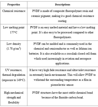
10 Table 2.1: General properties of PVDF (Frank, 2014).
Properties Descriptions
Chemical resistance PVDF is made of composite fluoropolymer resin and ceramic pigment, making it a good chemical resistance
coating. Low melting point
177C
PVDF is an easy melted material and have a low melting point. It’s also easy to be processed compared to other
fluoropolymers. Low density
(1.78 g/cm3)
PVDF can be molded and is commonly used in the chemical and semiconductor as well as lithium ion batteries. It is also available as a crosslink closed cell foam
which used increasingly in aviation and aerospace applications.
UV resistance, thermal degradation (exposure to 149C).
It have very high fade resistance and ultraviolet resistance in extremely harsh environment. This will allow PVDF to
withstand the surrounding temperature as a film in piezoelectric sensor.
High mechanical strength and
flexibility
PVDF structures have the most stable chemical bond because of the fluoride-carbon bond.