DOI: 10.12928/TELKOMNIKA.v13i4.1357 1437
Design and Implementation of A Monitoring System for
Geological Archives
Sun Min
Public Security Technology Department, Hainan Vocational College of Political Science and Law, Haikou, Hainan, 570125, China
email: [email protected]
Abstract
A monitoring system for geological archives with TCP/IP network communication is designed in this research to address wide distribution range, long distance, slow data updating, and difficult maintenance of city and county geological archives. The designed system uses the single chip STC11F32XE and the Ethernet control chip RTL8019AS as a hardware platform. The hardware design scheme, software design method, and the main programming flowchart of the geological archive monitoring unit were presented, and a specific data test was carried out. This monitoring system not only monitors and controls temperature, humidity, ponding, power supply, and other environmental data in geological archives, but also realizes geological data transmission between city (county) and provincial geological archives. In addition, this system is designed with a GSM warning mechanism, which could accelerate the quick response mechanism of the system. The entire monitoring system is accessed through the provincial environmental resources website with a fixed IP address. To ensure standardization of the monitoring system, the data transmission standard of the application layer used the associated standards of the Ministry of National Land and Resources. The entire system design improves the storage environment of the geological data effectively. It provides important data support to solve inconsistencies between provincial and city (county) geological data, as well as ensures scientific management of geological issues.
Keywords: Geological data, Safety monitoring, Ethernet
Copyright © 2015 Universitas Ahmad Dahlan. All rights reserved.
1. Introduction
The promotion of digital management has improved the efficiency of the management of paper documents significantly in recent years. Paper documents that are almost one hundred years old are rare and valuable. High temperature, high humidity, drastic changes in temperature and humidity, power failure, and ponding damage these paper documents; such damage presents certain threats to the storage of digital documents [1]. The design and implementation of a monitoring system for geological archives have a significant application value.
2. Description of Geological Archive Monitoring System
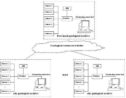
A geological archive safety monitoring system is a distributed measurement and control system that covers an entire province. Such a system is composed of a city (county) geological archive safety monitoring system, a provincial geological resources website, and a provincial monitoring center host. It involves concentrated monitoring of geological archives through computer technology, sensor technology, electronic technique, and communication technologies, all of which monitor and control the operation safety of the conditions of geological archives. The system also monitors operation parameters of equipment and record data, copes with failures, and ensures that early warning and alarms correspond to certain requirements. The monitoring center host of provincial geological archives could assess the operations of the city (county) geological archives.
The city (county) geological archive monitoring system consists of an environmental detector, a monitor, and a monitoring center host. The detector acquisition modulus transfers collected data to the monitor through 485 bus [5], and PCF8563 is used as the system clock. The monitor accesses the provincial National Land Environmental Resources’ IP network through a fixed IP address and then transfers data. The structure of the monitoring system for geological archives is shown in Figure 1.
Figure 1. Structure of the monitoring system for geological archives
3. System Hardware Design
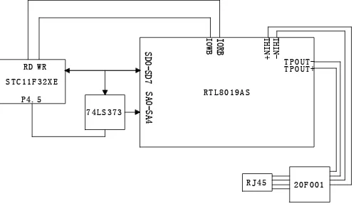
read-write operation of EEPROM [6]. Based on the geological resources website, the network chip RTL8019AS was used for Ethernet data transmission. RTL8019AS performances conform to Ethernet II and IEEE 802.3 standards, full duplex, and 10 mb/s transmit-receive rate [7]. The remote PC sends data to the Ethernet interface, which stores the data in the RAM. A field serial port device and a single chip were used for communication. The data from the RAM were collected as control command of the field equipment, thus changing the working state of the field equipment. STC11F32XE uses 8-bit data bus. Therefore, an 8-bit bus network card. IORB and IORB are connected with WR and RD of STC11F32XE, respectively. With respect to the connections of 20-bit bus of the RTL8019AS chip, SA0–SA4 are connected to P0.0–P0.4 of STC11F32XE. Five data buses are needed to address the 32 registers in the RTL8019AS chip. SA8 and SA9 are connected to VCC, and the other 13 address buses are connected to GND. The hardware structure is shown in Figure 2.
Figure 2. Hardware structure of the monitor
4. Upper Computer Software Design
A dedicated control lenlib.ocx under VB was set to ensure convenient data communication of the monitor through the Ethernet (provincial resources website) and one upper PC node of the Ethernet (provincial resources website). Users could invoke it on WINXP by installing the 10/100 Base-T Ethernet card on the PC. In this way, a distributed monitoring system based on the Ethernet could be achieved by embedding lenlib.ocx to design the network control system application software.
Lenlib.ocx is an ACTIVEX that uses lenuser object. It provides application developers with one attribute (remoteip), three methods [GetData(), SendData(), and Link()], and one event [dataarrival()]. The invoking steps are as follows:
(1) The PC is connected to the monitor. Remoteip attributes the IP address to the monitor. The PC and the monitor are connected through Link(). The connection is successful when the “ACK” string is received. Then, the next communication can be performed.
(2) Communication. After successful connection, GetData() is used to receive network data and SendData() is used to send data to the network. The PC will trigger DataArrival() after receiving the data from the monitor. GetData() in the DataArrival() is used to acquire the sent information and store it in variables of the variant type.
(3) SendData, GetData, link gramm Returned value Void
a. object.SendData data
b. object.GetData data, [type,] [maxLen]
5. Communication Protocol Design
According to related regulations of the Ministry of National Land and Resources, data transmission and communication protocol correspond to the application layer of the seven-layer
protocol defined by ISO/OSI, thereby providing mutual communication between field devices based on different transmission networks and monitoring centers [9].
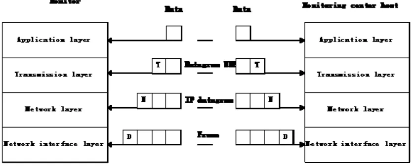
The application layer depends on the chosen transmission network and performs data communication on the chosen transmission network. If the basic transmission layer is established, then the protocol of the entire application layer is unrelated with the specific transmission network. In this system, the communication between the monitor and the monitoring center is based on TCP/IP, and the transmission layer uses the UDP protocol [10]. The communication between the monitor and the monitoring center host is shown in Figure 3.
Figure 3. Communication process of Ethernet
When the monitor wants to send data through UDP, it will transmit the data, a pair of socket addresses, and the data length, to the UDP. The UDP will then add UDP data prelude to the received data and then send it to the IP, marking it from the UDP protocol. Then, this IP datagram is sent to the data link layer (DLL). The DLL will add its prelude to the received datagram and then send it to the physical layer. The physical layer will convert these bit codes into an electrical signal and then transmit them [11]. When the monitoring center receives these data, it will unpack them layer by layer to obtain the real effective data and then make corresponding treatments.
Communications between the monitor and the upper computer use an incompressible ASCII pattern. The command format from the host to the terminal is
HEAD CLA LC DATA CRC END
Specific command definitions
The communication protocol mainly includes 11 commands. Command of collector time setting
(1) Definition and range: The upper computer sets the collector time. The direction is from the PC to the terminal.
(2) Command message
STAR WCLK 012 YYMMDDHHMMSS, 12 bits in total
XX END
(3) Response message
STAR WCLK 002 SW1 SW1 XX END
(4) Returning data meaning: SW1 SW2=“00”/“FF” (command is executed successfully/setting failed).
Command of collector time reading
(1) Definition and range: The upper computer reads the current time of the collector. The direction is from the PC to the terminal.
(2) Command message
STAR RCLK 000 Nothing XX END
STAR RCLK 012 YYMMDDHHMMSS, 12 bits in total
XX END
(4) Returning data meaning: Nothing. Command of collector upload interval setting
(1) Definition and range: The upper computer sets the upload interval of the collector. The direction is from the PC to the terminal.
(2) Command message
STAR WUPT 001 Interval mark of
1 byte can only be 0, 1, 2, and 3.
XX END
Note: DATA supports 0, 1, 2, and 3 only. Hence, other values are viewed as errors. 0 represents an untimed upload; 1 indicates an upload every 10 min; 2 indicates an upload every 30 min; and 3 indicates an upload every 60 min.
(3) Response message
STAR WUPT 002 SW1 SW1 XX END
(4) Returned data meaning: SW1 SW2=“00”/“FF” (command is executed successfully/setting failed).
Command of collector beginning to upload real-time data
(1) Definition and range: After the upper computer sends this command, the collector will return the current real-time data every 30 s until the upper computer stops sending the command to the collector. The direction is from the PC to the terminal.
(2) Command message
STAR SRDA 000 Nothing XX END
(3) Response message
STAR SRDA 002 SW1 SW1 XX END
(4) Returning data meaning: SW1 SW2=“00”/“FF” (command is executed successfully/setting failed).
Command of collector stopping to upload real-time data
(1) Definition and range: After the upper computer sends this command to the collector, the collector will stop returning the current real-time data state every 30 s. The direction is from the PC to the terminal.
(2) Command message
STAR ERDA 000 Nothing XX END
(3) Response message
STAR ERDA 002 SW1 SW1 XX END
(4) Returning data meaning: SW1 SW2=“00”/“FF” (command is executed successfully/setting failed).
Command of collector uploading real-time data
(1) Definition and range: After the upper computer sends a command to start collecting real-time data to the collector, the collector will send the current real-real-time data to the upper computer every 30 s. The direction is from the terminal to the PC.
(2) Command message
Time Voltage Current Temperature Humidity UPS/air
conditioning switch
12 bytes 3 bytes 2 bytes 2 bytes 2 bytes 1 byte
(1111XXXX) Command of collector uploading data regularly
(2) Command message
Returning data meaning: SW1 SW2=“00”/“FF” (successful/failed data sending) Command of setting alarm threshold
(1) Definition and range: The upper computer sends an alarm threshold to the collector. The direction is from the PC to the terminal.
(2) Command message
STAR WBJY 009 Environmental parameter
threshold
XX END
where environmental parameter thresholds are
Voltage Current Temperature Humidity
3 bytes 2 bytes 2 bytes 2 bytes
(3) Response message
STAR WBJV 002 SW1 SW1 XX END
(4) Returning data meaning: SW1 SW2=“00”/“FF” (successful/failed data sending). Alarm
(1) Definition and range: The collector sends an alarm signal to the upper computer. The direction is from the terminal to the PC.
(2) Command message
(4) Returning data meaning: SW1 SW2=“00”/“FF” (successful/failed data sending). Setting discharge starting time and time span
(1) Definition and range: The upper computer sets the discharge start time and time span of city (county) geological archives UPS. The direction is from the PC to the terminal.
(2) Command message
STAR WFDT 014 YYMMDDHHMMSS HH, 14 bytes
XX END
(3) Response message
STAR WFDT 002 SW1 SW1 XX END
(4) Returning data meaning: SW1 SW2=“00”/“FF” (successful/failed data sending). Setting archives switching control
(1) Definition and range: The upper computer sets the switching control signal for city (county) geological archives.
(4) Returning data meaning: SW1 SW2=“00”/“FF” (successful/failed data sending).
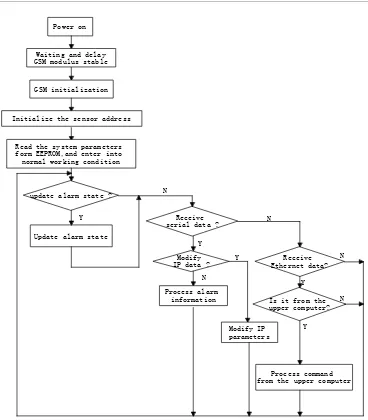
6. Main Program Flowchart of the Monitor
Figure 4. Main program flowchart of the monitor
7. System Test
The Ethernet linkage and the connection between the monitor and the detector were tested. Results are shown in Figures 5 and 6. The on/off test of the main supply and the test results of related processing are presented in Figure 7.
Figure 5. Ethernet linkage test Power on
GSM initialization
Initialize the sensor address
Read the system parameters form EEPROM,and enter into normal working condition
update alarm state ?
Receive serial data ? Update alarm state
Y
Modify IP data ? N
Y
Receive Ethernet data?
Is it from the upper computer? N
Y
Y N
Process alarm information
Modify IP parameters
Process command from the upper computer
N
N Y
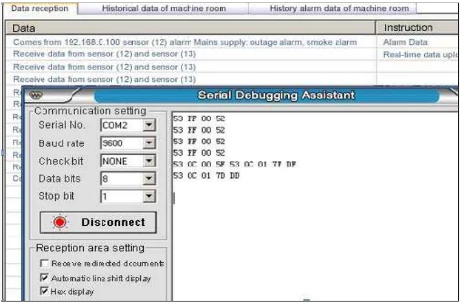
Figure 6. Received data and responses of monitor to control command
Figure 7. Outage alarm test
8. Conclusions
The monitoring system has achieved good overall operation in the Hainan Geological Archives since it became operational. The system met the design requirements of the Bureau of National Territory Resource of Hainan and provided data support for further data management. Given the emphasis on the “people-oriented” principle, the combination of new management and a continuously refined management mechanism ensured that geological data management is humanized. This approach also enhanced the enthusiasm and consciousness of geological staff and relieved their management burden, as well as improved management efficiency.
(1) The application of the geological archive safety monitoring system has fundamentally changed the original 24 h duty modes of managers.
The data support provided by the monitoring system guarantees the safety of the city (county) geological archives. It also provides accurate and intuitive digital information for geological safety management in Hainan, thereby accelerating the informatization of Hainan.e.
References
[1] Lou Hongying. The research on the situation and counter measures of the geologic data socialization. Master’s Thesis of China University of Geosciences, Beijing, China. 2011: 25-33. [2] Wang Jun, Meng Bao-ping, Song Lei. Brief Introduction of Tongchuan Broadcasting Networks
Sub-front-end Unattended Equipment Room Monitoring System Construction. China Digital Cable TV. 2011; 9: 1088-1089.
[3] Wang Qian-ju, Yan Shi-qiang, Wang Yong-sheng, Ma Fei-fei1, Yue Yong-bing.The Status, Problems and Counter measures and Suggestions of National Geological Archives. Natrual Resource Economics of China. 2011; 1: 18-19.
[4] Gong Wentao. The Design of Environmental Monitoring System based on Temperature and Humidity. Microcomputer Applications. 2013; 29(12): 17-18.
[5] Li Da-lian. Design of Equipment Room Environment Monitoring System based on TCP/IP. Computer and Modernization. 2011; 2: 97-98.
[6] STC micro. Manual of STC11/10XX series Singlechip, available from:
http://www.stcmcu.com/datasheet/stc/STC-AD-PDF/STC11F-10Fxx-english.pdf, accessed on 21-09-2015
[7] Elecfans. Data of REALTEK8019/REALTEK8019 as chip, available from:
http://www.elecfans.com/soft/78/223/2010/2010091990019.html, accessed on 08-10-2015
[8] Ethernet Gateway for Single Chip. Electronic Engineering World, available from: http://www.eeworld.com.cn/mcu/2015/0129/article_18279.html, accessed on 12-10-2015
[9] Ministry of Environmental Protection of China. Standard for data communication of pollution emission
auto monitoring system (HJ/T212-2005), available from: http://www.mep.gov.cn/image20010518/5836.pdf, accessed on 22-10-2015
[10] Navid Ghaffarzadeh, Masoud Akbar, Amir Khanjanzadeh. Distributed Generation Allocation to Improve Steady state Voltage Stability of Distribution Networks using Imperialist Competitive Algorithm. International Journal of Electrical and Computer Engineering. 2013; 2(2): 71-78.