I/We* have read this thesis and from my/our* opinion thesis
is sufficient in aspects of scope and quality for awarding Bachelor of Mechanical Engineering (Thermal Fluid)
Signature : ………..
Name of Supervisor : ………...
Date : ………...
THE STUDY OF THE AGGRESSIVE TURNING PROCESS ON ALUMINIUM FOR AUTOMOTIVE APPLICATIONS
CHAN MEI YEE
This report is presented as partial requirement for the completion of the Bachelor of Mechanical Engineering (Thermal Fluid) Degree Programme
Faculty of Mechanical Engineering Universiti Teknikal Malaysia Melaka
“I hereby, declare this thesis is result of my own research except for summary and quotes that cited in the references”
Signature : ………
Name of author : ………
ACKNOWLEDGEMENT
First and foremost, I would like to convey my most heartfelt acknowledgement to Mr. Hamzah bin Mohd Dom as the final year project supervisor who has offered his time, attention, experience and guidance throughout the completion of the study thus far. I would also like to extend my gratitude to Mr. Mazlan, Mr. Khairi and Mr. Muszaini for their assistance and provision of information on the materials, machine and tools for aggressive turning process.
Likewise, I would like to thank the Faculty of Mechanical Engineering, Universiti Teknikal Malaysia Melaka (UTeM) for giving the opportunity for students to learn how to apply the relevant knowledge of engineering in final year project by conducting investigation and analysis.
ABSTRAK
ABSTRACT
TABLE OF CONTENTS
CHAPTER TOPIC PAGE
DECLARATION ii
DEDICATION iii
ACKNOWLEDGEMENT iv
ABSTRAK v
ABSTRACT vi
TABLE OF CONTENTS vii
LIST OF TABLES x
LIST OF FIGURES xi
LIST OF SYMBOLS xiii
LIST OF APPENDICES xiv
1 INTRODUCTION 1
1.1 Background Study 1
1.2 Problem Statement 2
1.3 Objectives 2
1.4 Scope 3
1.5 Importance of Study 3
2 LITERATURE REVIEW 4
2.1 Aluminium 4
2.2 Aluminium for Automotive Applications 4
2.3 Aluminium Alloys 7
2.4 Turning 10
2.5 Single-point Cutting Tool 11
2.6 Tungsten Carbide Inserts 12
2.7 Aggressive Turning / High Speed Turning 13 2.8 Spindle Speed, Feed Rate and Depth of Cut 14
2.9 Tool Wear 15
2.10 Chip Formation 16
2.11 Cutting Fluids 18
2.12 Design of Experiments 19
3 METHODOLOGY 21
3.1 Flow Chart 21
3.2 Literature Research 22
3.3 Defining Experiment Parameters 22
Using DOE Method
3.4 Aggressive Turning Experimentation 25
3.4.1 Experimental Design 25
3.4.2 Experimental Method 26
3.5 Visual Inspection on Aluminium 31
4 RESULTS AND DISCUSSIONS 32
4.1 Turning Process 33
4.2 Facing Process 40
5 CONCLUSION AND RECOMMENDATIONS 44
5.1 Conclusion 44
REFERENCES 46
APPENDIX A 49
APPENDIX B 52
APPENDIX C 54
LIST OF TABLES
NO. TITLE PAGE
2.1 Properties of steel and aluminium 5
2.2 Manufacturing properties and typical applications 8 of selected wrought aluminium alloys
2.3 Various turning process according to the direction 10 of tool feed
3.1 Theoretical process parameters of the design of experiments 24 3.2 Actual process parameters of the design of experiments 25
3.3 Turning Process 26
3.4 Facing Process 29
LIST OF FIGURES
NO. TITLE PAGE
2.1 Typical relative and average absolute weight savings 5 of aluminium
2.2 Aluminium applications in a car 6
2.3 Development of aluminium consumption for 6 automotive application in Europe
2.4 Schematic diagram of turning process 10
2.5 Schematic diagram of facing process 11
2.6 Standard cutting tools 11
2.7 High speed cutting ranges in machining of various 13 materials
2.8 Basic machining parameters in turning 15
2.9 Flank wear 16
2.10 Crater wear 16
2.11 Continuous chip 17
2.12 Discontinuous chip 17
2.13 Continuous chip with built-up edge 18
3.1 Flow chart of the methodology of aggressive turning 21 on aluminium
4.2 Graph of difference between theoretical and actual 36 value for depth of cut (medium spindle speed)
4.3 Graph of difference between theoretical and actual 38 value for depth of cut (high spindle speed)
4.4 Aluminium rod for experiment no.9 39
4.5 Coarse and uneven surface 39
LIST OF SYMBOLS
Concise list of symbols in order of appearance:
ρ = density of metal E = modulus of elasticity s = tensile strength E/ρ = specific stiffness s/ρ = specific strength
v = cutting speed of the workpiece D = initial diameter of the workpiece n = spindle speed of the workpiece f = rate of feed in mm/min
S = tool feed in mm/rev t = depth of cut
LIST OF APPENDICES
NO. TITLE PAGE
A PSM Planning Schedule 50
B Okuma Space Turn LB 200-R 53
C Taegu Tec Cutting Tool 55
CHAPTER 1
INTRODUCTION
1.1 Background Study
Turning is one of the main types of machining where material is removed using a cutting tool. It allows rotating parts to be produced using a single-edge cutting tool. The cutting tool is set at a certain depth of cut (mm or inch) and travels to the left with a certain velocity as the workpiece rotates (Kalpakjian and Schmid 2006).
High speed machining (HSM) was first develop by German inventor during year 1920 and now widely spread in variety of manufacturing industry included aerospace and automotive sectors where to produce high precession and accuracy parts. Major advantages of high speed machining are high material removing rate, reduction of lead time and the most important is increase parts precision and surface finish. Nowadays, many industries facing challenge to improve the quality of products and processes with minimum cost and time constraints. One obvious benefit of HSM in general is that at high spindle speed the feed can be increased proportionally with the same chip-load as in conventional machining (Hamade and Ismail 2005).
for the material and tools will greatly affect tool life and the quality of the surface finish. Feed rate is the velocity at which the cutter is advanced against the workpiece. When deciding what feed rate to use for a certain cutting operation, the calculation is fairly straight forward for single-point cutting tools. The ratio of the spindle speed and the feed rate controls how aggressive the cut is, and the nature of the chips formed. Depth of cut is defined as the thickness of material removed from a workpiece in a single machining part (Davis 1998). General machine practice is to use a depth of cut up to five times the rate of feed. If chatter or machine noise develops, the depth of cut will be reduced.
From a material point of view, aluminium is a soft metal that has the face-centered cubic (FCC) unit cell structure, which is one reason why aluminium is an easy-to-machine metal with machinability ratings superior to those of most engineering metals. This same property makes aluminium a metal that lends itself easily to high-speed machining in general (Hamade and Ismail 2005).
1.2 Problem Statement
Currently, there has yet to be any comprehensive study on the aggressive turning on aluminium for automotive applications. No any significant data showing how aggressively and effectively aluminium can be turned. Providing such data can help users to improve the turning process on aluminium.
1.3 Objectives
• To study the potential benefits and challenges of the Aggressive Turning process on aluminium
1.4 Scope
The study will focus on the effectiveness of the aggressive turning practice by DOE method. The Okuma Space Turn LB 200-R CNC lathe machine will be used in the experiment. The conditions of the aluminium after been aggressive turned will be analyzed by using visual inspection method.
1.5 Importance of Study
The aggressive turning of aluminium by controlling the parameters could help the automotive industry to improve production rate and increase the challenges in the global markets. Besides, DOE method could help the industry to save time and cost.
1.6 Expected Results
CHAPTER 2
LITERATURE REVIEW
2.1 Aluminium
According to Hamade and Ismail (2005), Aluminium is a soft, low density (ρ) metal that appeals to weight sensitive industries because of its competitive specific stiffness (E/ρ) and strength (s/ρ) where E is the modulus of elasticity and s is the tensile strength. Aluminium in pure form is not very useful for forming into structural material. Almost all aluminum used for aircraft parts or car parts or other structures is an alloy. With 2,700 kg/m3, the density of aluminium is one third of that of steel. Aluminium allows a saving of up to 50% of weight over competing materials in many applications.
2.2 Aluminium for Automotive Applications
Table 2.1: Properties of steel and aluminium (Source: Carle and Blount, 1999)
From the table 2.1, the strength of aluminium sheet panels and extruded sections is approximately the same as that of steel body distortion or a break of the panel the same force must be applied. However, the rigidity of aluminium is lower than that of steel. That is partly due to the modulus of elasticity of aluminium that is just one-third that of steel (Carle and Blount 1999).
The average mass of passenger cars has dramatically increased since the 1970's and due to vehicle weight directly impacts fuel consumption, light-weighting is necessary more than ever to reduce CO2 emissions per km at the exhaust pipe. Typical relative and average absolute weight savings of today’s main aluminium applications in mass-produced cars are given below (European Aluminium Association, 2007).
Figure 2.2: Aluminium applications in a car (Source: European Aluminium Association, 2007)
Figure 2.3: Development of aluminium consumption for automotive application in Europe (Source: Bassi et al., 1999)
cylinder heads, 85% of intake manifolds and transmission (other parts-rear axle, differential housings and drive shafts etc.) For chassis applications, aluminium castings are used for about 40% of wheels, and for brackets, brake components, suspension (control arms, supports), steering components (air bag supports, steering shafts, knuckles, housings, wheels) and instrument panels.
Aluminium alloys have also found extensive application in heat exchangers. The market share of aluminium has grown steadily over the last 25 years and is now the material of choice for use in the automotive heat exchanger industry. Modern, high performance automobiles have many individual heat exchangers, e.g. engine and transmission cooling, charge air coolers (CACs), climate control (Miller et al. 2000).
2.3 Aluminium Alloys
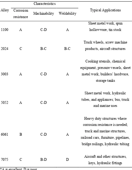
Table 2.2: Manufacturing properties and typical applications of selected wrought aluminium alloys (Source: Kalpakjian and Schmid, 2006)
Alloy
Characteristics
Typical Applications Corrosion
resistance Machinability Weldability
1100 A C-D A
Sheet metal work, spun hollowware, tin stock
2024 C B-C B-C
Truck wheels, screw machine products, aircraft structures
3003 A C-D A
Cooking utensils, chemical equipment, pressure vessels, sheet
metal work, builders’ hardware, storage tanks
5052 A C-D A
Sheet metal work, hydraulic tubes, and appliances; bus, truck
and marine uses
6061 B C-D A
Heavy duty structures where corrosion resistance is needed;
truck and marine structures, railroad cars, furniture, pipelines,
bridge railings, hydraulic tubing
7075 C B-D D Aircraft and other structures,
Davis (1998) stated that most aluminium alloys can be machined at very high speeds because tool life is not an important consideration or limitation. However, the high-silicon alloys such as 380 (8.5% Si) and 390 (17% Si) are exceptions. According to the theories of metallurgical thermodynamics alloying elements can enter the crystal structure as solid solution or build various constituent phases depending on composition, temperature and on the kinetics of nucleation and growth processes. The types of phases existing in an alloy of given composition and at various temperature regimes are mapped in phase diagrams. The parameters of the complete chain of thermo-mechanical processes in the production of a cast or wrought product influence the type and distribution of alloying elements and constituent phases in the microstructure and thereby determine the properties and behaviour of the product. (Aluminium Automotive Manual 2008)
The specific properties of aluminum alloys must be considered (ESPI metals 2008):
• Their density allows high speeds of rotation and translation as the inertia of aluminum alloy chip is less than that of steel.
• Their modulus of elasticity, which is one third that of steel, requires appropriate chucking and clamping arrangements that avoid deformation and distortion. The alloy’s thermal conductivity assists with heat dissipation.
• Given the high rate of chip removal, the heat generated by the machining process is taken away with the chip without having the time to diffuse into the metal. • A coefficient of linear expansion that is twice that of steel makes heating
2.4 Turning
El-Hofy (2007) studied that turning is a method of machining by cutting in which the workpiece carries out the main rotary motion while the tool performs the linear motion. The process is used for the external and internal turning of surfaces. The basic motions of the turning process are
1. The primary motion is the rotary motion of the workpiece around the turning axis. 2. The auxiliary motion is the linear motion of tool, also called the feed motion.
Table 2.3: Various turning process according to the direction of tool feed (Source: El-Hofy 2007)
Types of turning process Direction of tool feed Straight turning Parallel to the turning axis
Taper turning Intersects with the turning axis Traverse turning Perpendicular to the turning axis
Figure 2.4: Schematic diagram of turning process (Source: www.efunda.com)
Figure 2.5: Schematic diagram of facing process (Source: www.efunda.com)
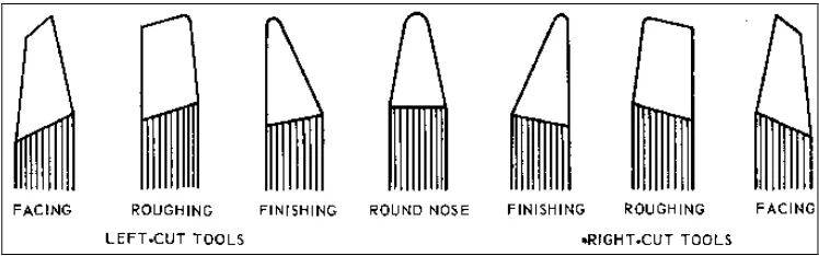
2.5 Single-point Cutting Tool
Figure 2.6: Standard cutting tools (Source: www.nmis.org)
A single point cutter bit is a tool that has only one cutting action proceeding at a time.Single-point lathe tools can be used in various ways:
• Facing tools are ground to provide clearance with a center.
• Roughing tools have a small side relief angle to leave more material to support the cutting edge during deep cuts.
• Finishing tools have a more rounded nose to provide a finer finish. Round nose tools are for lighter turning. They have no back or side rake to permit cutting in either direction.
help strengthen the tool bit and provide for a smooth cutting action. The ground tool bit is held rigidly by a tool holder while it is cutting.
The overall shape of the lathe tool bits can be rounded, squared, or another shape as long as the proper angles are included. Tool bits are identified by the function they perform, such as turning or facing. They can also be identified as roughing tools or finishing tools.
2.6 Tungsten Carbide Inserts
Carbide inserts can be square, triangular, round, diamond or other shapes. The strength of the cutting edge of an insert depends on its shape. The smaller the included angle, the strength of the edge is lower. In order to improve edge strength and prevent chipping, all insert edges usually are honed, chamfered, or produced with a negative land. Most inserts are honed to a radius of about 0.025mm (Kalpakjian and Schmid 2006).
2.7 Aggressive Turning / High Speed Turning
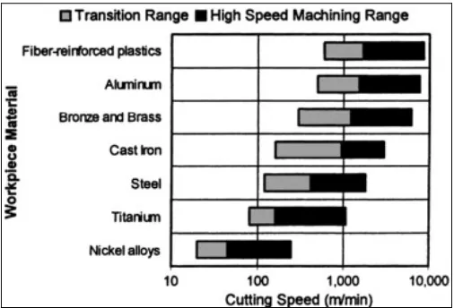
Aggressive turning or high speed turning is one of the processes of high speed machining. High speed machining (HSM) or high speed cutting (HSC), for a given material, is defined as the cutting speed above which shear localization develops completely in the primary shear zone. One suggestion is that 600 to 1800 m / min should be termed as high speed machining, 1800 to 18000 m / min very high speed machining, and greater than 18000 m / min as ultrahigh speed machining. High speed machining finds many industrial applications due to the development of tougher, more refractory tool materials and of high speed machining spindles. HSM can be used to machine parts that require the removal of significant amounts of material and to machine long, thin webs (El-Hofy 2007).
However, in comparison with high-speed milling and grinding, high-speed turning has not been widely applied in batch production. The main reason for this lies in the relatively short continuous cutting time, and lack of a workpiece clamping system that is safe and flexible at high rotational speeds ( Feng et al. 2008).
Figure 2.7: High speed cutting ranges in machining of various materials (Source: Schulz and Moriwaki, 1992)
chip removal resulting in decrease in workpiece distortion and increase part precision and surface finish. High speed turning is being used to reduce lead-times and manufacturing costs. The high speed turning is recognized as a main manufacturing technology for higher productivity and throughput (Schulz and Moriwaki 1992).
The study from Vaughn (1958) showed a series of variables involved in the traditional machining that became very important in HSM. Accordingly, the rate at which the metal can be machined is affected by:
• Size and type of the machine • Cutting tool used
• Power available • Material to be cut
• Speed, feed, and depth of cut
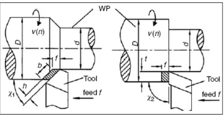
2.8 Spindle Speed, Feed Rate and Depth of Cut
The speed of the cutting motion or the peripheral speed of the workpiece is calculated in m/min (Youssef 2008):
Figure 2.8: Basic machining parameters in turning (Source: Youssef, 2008)
The feed or feed rate is the distance the tool travels horizontally per unit revolution of the workpiece (mm/rev). The rate of feed f in mm/min is expressed by
Where S is the tool feed in mm per revolution (El-Hofy 2007).
Depth of cut is the thickness of material removed in a machining operation. Depth of cut t, which is measured in a direction perpendicular to the workpiece axis, for one turning pass.
Where d is the diameter of the machined surface (Youssef 2008).
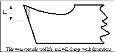
2.9 Tool Wear
Tool wear is a significant problem in cutting. It is defined as a gradual deterioration of tools. For cutting tools, the following ones are the most frequent occurred. Two types of wear include:
Figure 2.9: Flank wear (Source: www.eod.gvsu.edu)
• Crater wear in which contact with chips erodes the rake face. This is somewhat normal for tool wear, and does not seriously degrade the use of a tool until it becomes serious enough to cause a cutting edge failure.
Figure 2.10: Crater wear (Source: www.eod.gvsu.edu)
Tool wear will increase cutting forces and cutting temperatures. It also decreased accuracy of finished part and a poor surface finish will be obtained. Reduction in tool wear can be accomplished by using lubricants and coolants while machining.
2.10 Chip Formation
[image:31.612.236.420.266.352.2]where the tool meets the work. During the machining process three basic types of chips are formed:
Continuous Chip
[image:32.612.262.392.232.350.2]This leaves the tool as a long ribbon and is common when cutting most ductile materials such as mild steel, copper and aluminium. It is associated with good tool angles, correct speeds and feeds, and the use of cutting fluid.
Figure 2.11: Continuous chip (Source: mmu.ic.polyu.edu.hk)
Discontinuous Chip
The chip leaves the tool as small segments of metal resulted from cutting brittle metals such as cast iron and cast brass with tools having small rake angles.
[image:32.612.262.393.500.619.2]Continuous Chip with Built-up Edge (BUE)
[image:33.612.263.392.192.311.2]This is a chip to be avoided and is caused by small particles from the workpiece becoming welded to the tool face under high pressure and heat. The phenomenon results in a poor finish and damage to the tool. It can be minimized or prevented by using light cuts at higher speeds with an appropriate cutting lubricant.
Figure 2.13: Continuous chip with built-up edge (Source: mmu.ic.polyu.edu.hk)
2.11 Cutting Fluids
Cutting fluids play a significant role in machining operations and impact shop productivity, tool life and quality of work. The primary function of cutting fluid is temperature control through cooling and lubrication (Aronson et al. 1994). A fluid's cooling and lubrication properties are critical in decreasing tool wear and extending tool life. Cooling and lubrication are also important in achieving the desired size, finish and shape of the workpiece (Sluhan 1994). A secondary function of cutting fluid is to flush away chips and metal fines from the tool / workpiece interface to prevent a finished surface from becoming marred and also to reduce the occurrence of built-up edge (BUE). Practically all cutting fluids presently in use fall into one of four categories:
• Straight oils
• Soluble oils
• Semisynthetic fluids
2.12 Design of Experiments
Design of Experiments (DOE) refers to experimental methods used to quantify indeterminate measurements of factors and interactions between factors statistically through observance of forced changes made methodically as directed by mathematically systematic tables. It is one of the many problem-solving quality tools that can be used for various investigations such as finding the significant factors in a process, the effect of each factor on the outcome, the variance in the process, troubleshooting the machine problems, screening the parameters, and modelling the processes. By using strategically designed and statistically performed experiments, it is possible to study the effect of several variables at one time, and to study inter-relationships and interactions (Konda et al. 1999).
A full factorial designed experiment consists of all possible combinations of levels for all factors. A full factorial experiment assists experimenters to study all possible combinations of the levels of the factors or process parameters in the experiment. By performing a full factorial experiment, one may be able to study the joint effects of two factors (or interactions) on a response by simultaneously changing the levels of factors. One of the major limitations of full factorial designs is that the size of the experiment is a function of the number of factors considered and to be studied for the experiment. (Antony 2003)
The strategy that used in designing, performing, and analyzing experiments is shown below:
• Step 1 - Identify the potential factors by brainstorming a cause and effect design diagram.
• Step 2 - Choose the factors for the study.
• Step 3 - Select the appropriate working range for each potential factor considered in Step 2.
• Step 5 - If possible, trial run or dry run the experiments with all possible combinations within the range of each factor selected in an extremely short run to guard against a process failure owing to interactions.
• Step 6 - Choose an orthogonal array for experiments or any experimental design (full factorial or fractional factorial).
• Step 7 - Run experiments as designed. Experiments must be performed randomly.
• Step 8 - Analyze the experimental results for the objective of the project. Draw conclusions and verify them with the objective evidence.
CHAPTER 3
METHODOLOGY
[image:36.612.243.412.311.705.2]3.1 Flow Chart
In order to systematically satisfy the research objectives, the research methodology was applied and can be mainly divided in 4 major divisions:
3.2 Literature Research
At this initial stage, basic information regarding aggressive turning was obtained. In addition to that, supplementary research regarding the materials and tools required to successfully run the experiment and achieve the objectives were conducted. These include journal research on aggressive turning of aluminium; the study of tool wear and chip formation; and other directly or indirectly issue that would contribute to the success of the experiment.
3.3 Defining Experiment Parameters Using DOE Method
Figure 3.2: The aluminium rod that used in CNC lathe machine
In this present work, a 3k factorial design has been used for developing the non-linear mathematical model with three levels (k=3) so that all interactions between the process parameters could be investigated effectively. The three input process parameters considered were spindle speed, feed rate and depth of cut. The diameter was not treated as an input process parameter in the design of experiments as it changes in each pass with the depth of cut. The three levels for each factor were chosen on the basis of data given in machining books, machine capabilities and workshop practice.
According to El-Hofy (2007), the cutting speed v for high speed machining is 600 to 1800 m/min. By using the equation below, the spindle speed range, n for high speed machining can be obtained:
For v = 600 m/min,
n = 1000 (600m/min) / π (25.4 mm) = 7519 rpm
For v = 1800 m/min,
Therefore, the spindle speed of high speed machining is around 7519 – 22557 rpm. According to Kalpakjian (1997), the depths of cut are generally in the range of 0.5 – 12 mm while feed rate is usually in the range of 0.15 – 1 mm/rev. A total number of 27 experiments (33) runs have planned to be carried out within the following selecting range of input process parameters for turning process and facing process respectively:
[image:39.612.115.537.299.383.2]• Spindle speed: 10000 – 20000 rpm • Feed Rate: 0.15 – 1.0 mm/rev • Depth of cut: 0.5 – 12.0 mm
Table 3.1: Theoretical process parameters of the design of experiments Process Parameters Low level Medium level High level
Spindle Speed, n (rpm) 10000 15000 20000
Feed Rate, f (mm/rev) 0.15 0.5 1.0
Depth of Cut, t (mm) 0.5 5.0 12.0
Table 3.2: Actual process parameters of the design of experiments Process Parameters Low level Medium level High level
Spindle Speed, n (rpm) 1000 2000 3000
Feed Rate, f (mm/rev) 0.15 0.3 0.5
Depth of Cut, t (mm) 0.5 1.0 1.5
3.4 Aggressive Turning Experimentation
3.4.1 Experimental Design
To ensure the experiment can run successfully, the machine and tools needed have been determined. The Okuma Space Turn LB 200-R CNC lathe machine was used to carry out the experiment. This machine was selected due to it is the only available machine that near to the high spindle speed range. Taegu Tec triangle tungsten carbide insert with an angle of 60° was used to do turning process and facing process on the aluminium rod. No coolant was used for both processes because only rough cut has to carry out in the experiments. Rough cut is defined as a cut on the workpiece for the purpose of removing large amounts of material without concern for resulting surface finish. When making a rough cut, the surface finish is of no importance. Also, finish cuts often require certain accuracy that naturally achieves a good surface finish.
[image:40.612.247.408.547.693.2]Figure 3.4: Taegu Tec triangle tungsten carbide insert
3.4.2 Experimental Method
Table 3.3: Turning Process
1. The machine was switched on and the aluminium rod was gripped in the chuck.
[image:41.612.110.549.309.708.2]3. The cutting tool was moved closer at about 500 mm distance from the aluminium rod on both x-axis and z-axis.
4. Rough cut was done on the aluminium rod to remove a thin layer from it. The distance travelled along the rod was set as 50 mm.
6. After turning process, the outer diameter the aluminium rod was measured again by using digital vernier caliper. The turning process was repeated on the same rod for one spindle speed.
7. The surface condition of the aluminium rod and the chip formation after turning were also recorded.
Table 3.4: Facing Process
1. The machine was switched on and the aluminium rod was gripped in the chuck.
2. The tool turret was indexed with reference tool to the working position.
4. Rough cut was done on the face of aluminium rod to remove a thin layer from it.
5. After facing process, the surface condition of the aluminium rod and the chip formation were recorded in the table.
3.5 Visual Inspection on Aluminium
CHAPTER 4
RESULTS AND DISCUSSIONS
[image:47.612.136.514.526.612.2]Through the design of experiments (DOE) method, an experiment matrix was carried out by using the combinations of low, medium and high level of the process parameters. Collections of aggressive turning test data have been accomplished and tabulation of the data has done. The main direction of the analytical work was towards the effect of spindle speed, feed rate and depth of cut on the aluminium. The challenges of aggressive turning such as tool wear, surface condition and chip formation have been investigated for the turning and facing process. Once all the experiment data have been scrutinized, inferences in regard with the objectives of the study has made justified by conclusive results.
Table 4.1: Process parameters and their levels for the experiment Process Parameters Low level Medium level High level
Spindle speed, n (rpm) 1000 2000 3000
Feed rate, f (mm/rev) 0.15 0.3 0.5
4.1 Turning Process
Table 4.2: Low level spindle speed for turning process Spindle Speed, n (rpm) Feed Rate, f (mm/rev) Depth of Cut, t (mm) Diameter Difference (mm) Surface
Condition Chip Formation Before
(mm)
After (mm)
1000 0.15 0.5 24.92 24.41 0.51 smooth surface long, thin, continuous chip
1000 0.15 1.0 24.41 23.40 1.01 smooth surface long,
continuous chip
1000 0.15 1.5 23.40 21.91 1.49 smooth surface short,
continuous chip
1000 0.3 0.5 21.91 21.51 0.40 fine threaded
rough surface
long, continuous chip
1000 0.3 1.0 21.51 20.49 1.02 fine threaded
rough surface
long, continuous chip
1000 0.3 1.5 20.49 18.99 1.50 fine threaded
rough surface
short, continuous chip
1000 0.5 0.5 18.99 18.63 0.36 coarse threaded
rough surface
short, thin continuous chip
1000 0.5 1.0 18.63 17.63 1.00 coarse threaded
rough surface
short, continuous chip
1000 0.5 1.5 17.63 16.15 1.48 coarse threaded
rough surface
Figure 4.1: Graph of difference between theoretical and actual value for depth of cut (low spindle speed)
Table 4.3: Medium level spindle speed for turning process Spindle Speed, n (rpm) Feed Rate, f (mm/rev) Depth of Cut, t (mm) Diameter Difference (mm) Surface
Condition Chip Formation Before
(mm)
After (mm)
2000 0.15 0.5 25.13 24.61 0.52 smooth surface long, thin, continuous chip 2000 0.15 1.0 23.83 22.65 1.18 smooth surface long, continuous
chip 2000 0.15 1.5 21.77 20.16 1.61 smooth surface short, continuous
chip with BUE
2000 0.3 0.5 24.61 24.15 0.46 fine threaded
rough surface
long, continuous chip
2000 0.3 1.0 23.83 22.14 1.69 fine threaded
rough surface
short, continuous chip
2000 0.3 1.5 20.16 18.69 1.47 fine threaded
rough surface
short, continuous chip with BUE
2000 0.5 0.5 24.15 23.83 0.32 coarse threaded
rough surface
long, continuous chip
2000 0.5 1.0 22.14 21.77 0.37 coarse threaded
rough surface
short, continuous chip
2000 0.5 1.5 18.69 17.21 1.48 coarse threaded
rough surface
Figure 4.2: Graph of difference between theoretical and actual value for depth of cut (medium spindle speed)
tool and degrades surface finish. The formation of BUE has negative effects on the quality of the aluminium rod; especially a reduction in the dimensional control of the depth of cut which was due to the dynamically changing geometry of the cutting tool.
Table 4.4: High level spindle speed for turning process Spindle Speed, n (rpm) Feed Rate, f (mm/rev) Depth of Cut, t (mm) Diameter Difference (mm) Surface
Condition Chip Formation Before
(mm)
After (mm)
3000 0.15 0.5 25.10 24.59 0.51 helical threaded rough surface
long, continuous chip with BUE 3000 0.15 1.0 23.76 22.65 1.11 helical threaded
rough surface
long, continuous chip with BUE
3000 0.15 1.5 20.76 19.20 1.56 coarse threaded
rough surface
long, continuous chip with BUE
3000 0.3 0.5 24.59 24.18 0.41 helical threaded
rough surface
long, continuous chip with BUE
3000 0.3 1.0 22.65 21.65 1.00 coarse threaded
rough surface
long, continuous chip with BUE
3000 0.3 1.5 19.20 17.68 1.52 fine threaded
rough surface
long, continuous chip with BUE
3000 0.5 0.5 24.18 23.76 0.42 fine threaded
rough surface
long, continuous chip with BUE
3000 0.5 1.0 21.65 20.76 0.89 coarse threaded
rough surface
long, continuous chip with BUE
3000 0.5 1.5 17.68 N/A N/A coarse and
uneven surface
Figure 4.3: Graph of difference between theoretical and actual value for depth of cut (high spindle speed)
combination of high level process parameters. The diameter of the aluminium rod cannot be measured due to the coarse and uneven surface. Flank wear on the cutting tool was observed after all 27 experiments for turning process were carried out. The silver residual on the cutting tool indicates that the particles of the aluminium rod weld to the rake face of the tool during turning process. The chips formed are spiral shaped and the chip thickness has increased as the depth of cut was increased for the three levels of turning process.
[image:54.612.228.462.395.538.2]Figure 4.4: Aluminium rod for experiment no.9
Figure 4.5: Coarse and uneven surface
[image:54.612.263.426.572.691.2]4.2 Facing Process
Table 4.5: Low level spindle speed for facing process Spindle Speed, n (rpm) Feed Rate, f (mm/rev) Depth of Cut, t (mm) Surface
Condition Chip Formation
1000 0.15 0.5 smooth surface long, thin, continuous chip 1000 0.15 1.0 smooth surface short, continuous
chip 1000 0.15 1.5 smooth surface long, continuous
chip
1000 0.3 0.5 fine threaded
rough surface
long, thin, continuous chip
1000 0.3 1.0 fine threaded
rough surface
short, continuous chip with BUE
1000 0.3 1.5 fine threaded
rough surface
short, continuous chip with BUE 1000 0.5 0.5 coarse threaded
rough surface
short, continuous chip with BUE 1000 0.5 1.0 coarse threaded
rough surface
short, continuous chip with BUE 1000 0.5 1.5 coarse threaded
rough surface
Table 4.6: Medium level spindle speed for facing process Spindle Speed, n (rpm) Feed Rate, f (mm/rev) Depth of Cut, t (mm) Surface
Condition Chip Formation
2000 0.15 0.5 scratched marks on surface
long, thin, continuous chip 2000 0.15 1.0 scratched marks
on surface
short, continuous chip 2000 0.15 1.5 scratched marks
on surface
short, continuous chip
2000 0.3 0.5 fine threaded
rough surface
long, continuous chip with BUE
2000 0.3 1.0 fine threaded
rough surface
short, continuous chip with BUE
2000 0.3 1.5 fine threaded
rough surface
short, continuous chip with BUE 2000 0.5 0.5 coarse threaded
rough surface
short, continuous chip with BUE 2000 0.5 1.0 coarse threaded
rough surface
short, continuous chip with BUE 2000 0.5 1.5 coarse threaded
rough surface
Table 4.7: High level spindle speed for facing process Spindle Speed, n (rpm) Feed Rate, f (mm/rev) Depth of Cut, t (mm) Surface
Condition Chip Formation
3000 0.15 0.5 smooth surface long, thin, continuous chip
3000 0.15 1.0 fine threaded
rough surface
long, continuous chip
3000 0.15 1.5 fine threaded
rough surface
long, continuous chip
3000 0.3 0.5 fine threaded
rough surface
short, continuous chip with BUE
3000 0.3 1.0 fine threaded
rough surface
short, continuous chip with BUE
3000 0.3 1.5 fine threaded
rough surface
short, continuous chip with BUE 3000 0.5 0.5 coarse threaded
rough surface
short, continuous chip with BUE 3000 0.5 1.0 coarse threaded
rough surface
short, continuous chip with BUE 3000 0.5 1.5 coarse threaded
rough surface
It can be seen in the figures (refer Appendix D) that there were scratched marks on the surface of aluminium rod at medium level spindle speed and low level feed rate of 0.15 mm/rev. This could be due to the abrasive action of microhard carbide particles present in the material. At low level of feed rate, a thin and long continuous chip tends to form and a smooth surface was obtained. The increase of feed rate has caused the formation of shorter chip. The chips formed are spiral shaped. One common phenomenon for the three levels of facing process was the chip thickness has increased as the depth of cut was increased. The deformation of chip is generally found to be inhomogeneous. Experimental values show that the surface roughness values increases with feed rate. The formation of built up edge has occurred with the increasing of feed rate and depth of cut which has affect the surface quality of the aluminium rod. The absence of cutting fluid was also one of reason. Besides that, the silver residual on the cutting tool indicates that the particles of the aluminium rod weld to the rake face of the tool during facing process. No crack or breakage of the cutting tool was observed.
[image:58.612.107.548.484.571.2]For both turning process and facing process which were conducted by using DOE metod, the optimum parameters were selected based on the surface condition, cutting tool condition and the formation of the chips. It can be summarized as below:
Table 4.8 Optimum parameters for turning process and facing process
Turning Process Facing Process
Spindle Speed, n: 2000 rpm Feed Rate, f: 0.15 mm/rev
Depth of Cut, t: 0.5 mm
Spindle Speed, n: 3000 rpm Feed Rate, f: 0.15 mm/rev
CHAPTER 5
CONCLUSION AND RECOMMENDATIONS
5.1 Conclusion
5.2 Recommendations
The following are suggestions in the event of similar future studies:
1. Search for the suitable CNC lathe machine which can run high spindle speed from other universities or workshop.
2. Besides the effect of surface roughness, tool wear, and chip formation on aluminium, the study of the effect of heat to the aluminium should be carried out.
3. Use the aluminium that suitable for automotive applications such as aluminium 6061 in the studies.
REFERENCES
1. El-Hofy, H. (2007). “Fundamentals of Machining Processes: Conventional and Nonconventional Processes.” 1st Ed. Boca Raton, FL: CRC Press. pp. 107-108,
205-206
2. Kalpakjian, S. & Schmid, S. (2006). “Manufacturing Engineering and Technology.” 5th Ed. Jurong, Singapore: Prentice Hall. pp. 172, 607, 628, 655
3. Turning: Introduction. (n.d.). Retrieved 28th August 2008, from
http://aluminium.matter.org.uk/content/html/eng/default.asp?catid=128&pageid=214 4416321
4. Feed rate. (n.d.). Retrieved 12th September 2008, from
http://en.wikipedia.org/wiki/Feed_rate
5. Turning. (n.d.). Retrieved 24th September 2008, from
http://www.efunda.com/processes/machining/turn.cfm
6. Turning. (n.d.). Retrieved 25th September 2008, from http://en.wikipedia.org/wiki/Turning
7. Taegu Tec Ltd. (2006). “ISO Turn”. Korea: E-catalog.
8. Aluminium alloy. (n.d.). Retrieved 11th August 2008, from http://en.wikipedia.org/wiki/Aluminium_alloy
9. Aluminium in cars. (2007). Retrieved 15th August 2008, from http://www.eaa.net/en/applications/automotive/aluminium-in-cars/
10.Davis, J.R. (1998). “Metals Handbook” 2nd Ed. Materials Park, Oh.: ASM International. p. 917
11.The Aluminium Automotive Manual. Retrieved 4th October 2008, from
12.Machining aluminium. (2008). Retrieved 28th August 2008, from http://www.espi-metals.com/technicaldata.htm
13.Hamade, R.F. and Ismail F. (2005). “A case for aggressive drilling of aluminium”. Journal of Materials Processing Technology. 166(1). pp. 86-97
14.Carle, D. and Blount, G. (1999). “The suitability of aluminium as an alternative material for car bodies”. Materials & Design. 20(5). pp. 267-272
15.Miller, W.S. et al. (2000). “Recent development in aluminium alloys for the automotive industry”. Materials Science and Engineering. A280. pp. 37–49
16.Schulz, H. and Moriwaki, T. (1992). “High-speed machining”. Ann CIRP. 41(2). pp. 637–643
17.Youssef, H. A. (2008). “Machining Technology: Machine Tools and Operations”. Taylor & Francis Group. pp. 59-60
18.Choosing a Cutting Tool. (n.d.). Retrieved 25th September 2008, from
http://electron.mit.edu/~gsteele/mirrors/www.nmis.org/EducationTraining/machines hop/lathe/intro.html
19.Tool Bit. (n.d.). Retrieved 25th September 2008, from
http://en.wikipedia.org/wiki/Tool_bit
20. Tool Wear. (n.d.). Retrieved 28th September 2008, from
http://en.wikipedia.org/wiki/Tool_wear
21.Tool Wear. (2001). Retrieved 5th April 2009, from http://www.eod.gvsu.edu/eod/manufact/manufact-23.html#pgfId-147968
22.Chip Formation & Chip Breaker. (n.d.). Retrieved 6th April 2009, from http://mmu.ic.polyu.edu.hk/handout/0102/0102.htm
23.Cutting Fluid: Introduction. (n.d.). Retrieved 4th October 2008, from http://www.mfg.mtu.edu/cyberman/metal_fluids/history.html
24.Charlie (2002). Design of Experiments–DOE. Retrieved 2rd October 2008, from
http://www.isixsigma.com/dictionary/Design_of_Experiments_-_DOE-41.htm 25.Konda, R. et al. (1999). “Design of experiments to study and optimize process
26.Antony, J. (2003). “Design of experiments for engineers and scientists.” 1st Ed. Wheeler Road, Burlington: Butterworth-Heinemann. pp. 54-71
27.Kalpakjian, S. (1997). “Manufacturing Process for Engineering Materials.” 2rd Ed. Menlo Park, California, USA: Addison-Wesley. p.501
50 Appendix A: PSM Planning Schedule
PSM 1
No Task Week
1 2 3 4 5 6 7 8 9 10 11 12 13 14
1 Planning
2 Discussion with supervisor 3 Literature research
4 Introduction 5 Literature Review 6 Methodology
7 Expected Results and Discussion 8 Conclusion
51 PSM 2
No Task
Week
1 2 3 4 5 6 7 8 9 10 11 12 13 14 15 16 17 18 19
1 Planning
2 Discussion with supervisor and technician
3 Project Implementation
Design table for DOE
Execution of experiment
4 Compiling and analysis of data
Analyze data
Further literature research and reconfirm observations
Compile Chapter 3 and 4 (Prepare draft PSM report)
5 PSM 2 report and presentation
Final editing of PSM report
Submit PSM report
Appendix B: Okuma Space Turn LB 200-R
Appendix D: Figures of the Turning Process and Facing Process
Turning Process (Low level spindle speed)
Surface Condition Low Feed Rate
Spindle Speed = 1000 rpm Feed Rate = 0.15 mm/rev Depth of Cut = 1.5 mm
Medium Feed Rate
Spindle Speed = 1000 rpm Feed Rate = 0.3 mm/rev Depth of Cut = 0.5 mm
High Feed Rate
Turning Process (Medium level spindle speed)
Surface Condition and Chip Formation
Spindle Speed = 2000 rpm Feed Rate = 0.3 mm/rev Depth of Cut = 0.5 mm
Low Feed Rate Medium Feed Rate
Turning Process (High level spindle speed)
Surface Condition and Chip Formation
Spindle Speed = 3000 rpm Feed Rate = 0.15 mm/rev Depth of Cut = 0.5 mm
Low Feed Rate Medium Feed Rate
Facing Process (Low level spindle speed)
Surface Condition and Chip Formation Low Feed Rate
Medium Feed Rate
Facing Process (Medium level spindle speed)
Surface Condition and Chip Formation Low Feed Rate
Medium Feed Rate
Facing Process (High level spindle speed)
Surface Condition and Chip Formation Low Feed Rate
Medium Feed Rate