i
WIRELESS MICROPHONE SYSTEM
SUHAIDAH BINTI ABU BAKAR
This report is submitted in partial fulfillment of the requirements for the award of Bachelor of Electronic Engineering (Industrial Electronics)
With Honours
Faculty of Electronic and Computer Engineering Universiti Teknikal Malaysia Melaka
ii
UNIVERSTI TEKNIKAL MALAYSIA MELAKA
FAKULTI KEJURUTERAAN ELEKTRONIK DAN KEJURUTERAAN KOMPUTER
BORANG PENGESAHAN STATUS LAPORAN
PROJEK SARJANA MUDA II
Tajuk Projek : WIRELESS MICROPHONE SYSTEM
Sesi
Pengajian : 2008/2009
Saya SUHAIDAH BINTI ABU BAKAR
(HURUF BESAR)
mengaku membenarkan Laporan Projek Sarjana Muda ini disimpan di Perpustakaan dengan syarat-syarat kegunaan seperti berikut:
1. Laporan adalah hakmilik Universiti Teknikal Malaysia Melaka.
2. Perpustakaan dibenarkan membuat salinan untuk tujuan pengajian sahaja.
3. Perpustakaan dibenarkan membuat salinan laporan ini sebagai bahan pertukaran antara institusi pengajian tinggi.
4. Sila tandakan ( √ ) :
SULIT*
(Mengandungi maklumat yang berdarjah keselamatan atau kepentingan Malaysia seperti yang termaktub di dalam AKTA RAHSIA RASMI 1972)
TERHAD* (Mengandungi maklumat terhad yang telah ditentukan oleh
organisasi/badan di mana penyelidikan dijalankan)
TIDAK TERHAD
Disahkan oleh:
__________________________ ___________________________________
(TANDATANGAN PENULIS) (COP DAN TANDATANGAN PENYELIA)
Alamat Tetap NO 36, JALAN BAYAN 4, TMN BUKIT KATIL, 75450 BUKIT KATIL, MELAKA
iii
“I hereby declare that this report is the result of my own work except for quotes as cited in the references.”
Signature :………. Author : SUHAIDAH BINTI ABU BAKAR
iv
“I hereby declare that I have read this report and in my opinion this report is sufficient in terms of the scope and quality for the award of Bachelor of Electronic
Engineering (Industrial Electronics) With Honours.”
Signature :………. Supervisor’s Name : EN. MAZRAN BIN ESRO
v
vi
ACKNOWLEDGEMENT
By the name of the Almighty God, I am very thankful for this opportunity to express my highest gratitude firstly to Universiti Teknikal Malaysia Melaka (UTeM) for their willingness to accept me to undergo my degree programme. I would also like to thank them for their kind effort to provide me with all the facilities and technical expertise to make this programme successful.
Secondly, I would like to thank my supervisor, Mr. Mazran bin Esro and Mr Zamre bin Abd Ghani for their guidance and hard work on the technical and practical issues of this project. I really appreciate their dedication to ensure the completion of this project.
vii
ABTSRACT
viii
ABSTRAK
ix
CONTENTS
CHAPTER TITLE PAGE
PROJECT TITLE i
DECLARATION iii
DEDICATION v
ACKNOWLEGDEMENT vi
ABSTRACT vii
ABSTRAK viii
CONTENTS ix
LIST OF FIGURE xii
LIST OF REFERENCES xiv
1 INTRODUCTION OF PROJECT 1.1 Introduction 1
1.2 Problem statement 2
1.3 Objectives 2
1.4 Project Scope 3
1.5 Methodology 3
1.6 Report Structure 4
2 LITERATURE REVIEW 2.1 Introduction to Wireless Microphone system. 5
2.2 3V FM Transmitter 88Mhz to 108 Mhz by BF 982 7
2.3 FM wireless Microphone kit 7
2.4 Dynamic Microphone to Electret Microphone Input 8
x
2.6 Wireless microphone system for high quality sound 10
2.61 Filed of invention 10
2.62 Background of the invention 11 2.7 Wireless Home security system 13 2.8 Cordless FM mic. 13
3 METHODOLOGY
3.1 Introduction 14
3.2 Flow Chart 15
3.3 The Transmitter Circuit 16
3.4 The Receiver Circuit 19
3.5 The Audio Amplifier 21
3.6 The 10-LED VU meter 22
3.7 The IC LM 3914 23
3.8 The IC LM386N 29
3.9 The IC TDA 7000 31
3.10 The Electret Microphone System 32
3.1 The Antenna system 33
3.12 The Speaker System 34
4 RESULT
4.1 Results
4.1.1 Find the antenna 36
4.1.2 Find the speaker 37
4.2 Constructing Circuit 37
4.3 The housing sketch 42
4.4 Housing box model 43
xi
5 DISCUSSION 46
6 CONCLUSIONS & RECOMMENDATION
6.1 Conclusions 51
6.2 Recommendation 52
REFERENCES 53
xii
LIST OF FIGURE
NO TITLE PAGE
2.2 FM circuit with 3V transmitter by BF982 7
2.3 The FM wireless microphone kit. 8
2.4 The dynamic microphone. 8
2.5 Mic Circuit Test Oscillator 9
3.1 Wireless Microphone Transmit and Receive Signal 14
3.2 Flow Chart for Overall Project 15
3.3 The Transmitter circuit. 16
3.31a The block diagram of the transmitter. 17 3.31b Electronic tuned circuit in Oscillator. 18
3.32 The effected of the wave. 19
3.41 The receiver circuit. 19
3.42 The block diagram of the receiver 20
3.5 Audio amplifier 21
3.6 10-LED VU Meter for Power Amplifier 22
3.7 Block Diagram for IC LM3914 24
3.72 The circuit for voltage reference 25
3.73 Block Diagram for Mode Pin Function 27
3.8 Block Diagram for IC LM386N 30
3.9 The block diagram of IC TDA 7000 31
3.10 Electret condenser microphone capsules. 33
3.11 The Antenna 34
3.12 The speaker 35
4.1.1 Antenna 36
xiii
4.21 Simulation for Transmitter Circuit 37
4.22 Simulation for Transmitter Circuit 38
4.23 Transmitter Circuit 38
4.24 A receiver Circuit 39
4.25 A Constructed Transmitter Circuit 39
4.26 A Constructed Receiver Circuit 40
4.27 Receiver Circuit with power amplifier and 10-LED 40 VU meter.
4.28 The 10-LED VU meter linear analog display 41
4.31 Housing a Transmitter Circuit. 42
4.32 Housing a Receiver circuit and 10-LED VU Meter. 42
4.41 Transmitter Circuit Housing. 43
4.42 Housing of a Receiver circuit with 10-LED 44 VU Meter circuit.
4.43 Transmitter circuit located next to the housing model 44 4.44 The receiver circuits with 10-LED VU meter locate 45
next to the housing model
5.1 Wireless Microphone Transmit and Receive Signal 46 5.2 Datasheet for Integrated Circuit (IC) 48 5.3 Transmitter Circuit converted to Transmitter Layout. 48
5.4 UV Board after Etching Process 49
xiv
LIST OF REFERENCES
NO TITLE
A LM 2576 Datasheet
B TDA 7000 Datasheet
C LM 386N
1
CHAPTER I
INTRODUCTION
1.1 Project Introduction
Wireless Microphone System is build by using voice in its operation. This
wireless microphone system consist of a microphone, transmitter and receiver units
which operate in wireless method such as FM (frequency modulation). This is one of
main part of motorized wheelchair that transforms user voice by using wireless method
into the wheelchair movement. A wireless microphone, as the name implies, is a
microphone without a physical cable connecting it directly to the motorized wheelchair
controller.
The FM Microphone is really a miniature frequency modulated transmitter
operating in the standard FM broadcast band. The range of frequencies for the FM
broadcast band is 90MHz (MHz = Megahertz or 90 million cycles per second). Because
the FM microphone has a variable tuned circuit, it can be tuned to a quiet spot on our
local FM broadcast band for the best reception. When the small microphone element is
struck by sound, it converts the audio to a change in current through resistor. This
electrical change is amplified and eventually frequency modulates the transmitter. The
transmission range of the FM microphone is approximately 100 feet, depending on the
2
1.2 Problem Statement
A system which consists of wires interconnecting between devices would not
improve any problem or difficulties if the devices are static and not involve any physical
movement. However, for motorized wheelchair system that is hooked with a microphone
would require physical movement and the microphone is attached to the user. Therefore
wired system is not preferred. The same goes with Bluetooth headset as compared the
wired Hands free for the microphone. Of course people will prefer the first.
So that, this system is build for helping people. Use for people who physical
disability and need people help to move from one place to another (Voice as command).
So that, its can help patient to move easier and no need people help.
1.3 Objective Project
First is about to use a wireless system as a transmission and reception for my
system. Wireless communication is the transfer of information over a distance without
the use of electrical conductors or "wires". It is low-cost and easy to use proportionate to
the old microphone system. Now, we can see that it’s familiar to our life.
Second, to design and develop the wireless microphone system with 10-LED VU
meter. This wireless microphone system was design with combine the 10-LED VU
meter to show that the output voice can be detect by this LED.
Third, to design audio amplifier circuit for amplify the signal out between output
receiver and the speaker. This amplifier will amplify the signal for the clear and louder
3
1.4 The scope of this project are listed as follow:-
• Find the suitable circuit for transmitter and receiver that can function and can communicate each other.
• Construct the circuit and simulate in Multisim or PSpice software that can now the circuits can run or not.
• Designed the hardware for this system that will support distance mode 50 meter without any noise interruptions.
• Find the best navigator (antenna) that will give accurate signal for the both circuit.
1.5 Methodology
Phase1:-
Every weeks, meet and discuss with supervisor Mr Masran B. Esro and show the
project progress. Get the more information about wireless microphone from supervisor,
internet, books, journal, thesis, and so on. Firstly, I try to understand the concept &
desired result for this wireless microphone. After that, I get the datasheet of component
involved (antenna and speaker).
Phase2:-For this phase, I will do a survey to the entire previous wireless microphone
project for find the best method and rapprochement to my project. Do literature survey
from journal and internet.
Phase3:-
For this phase, I will find the best circuit such as transmitter circuit, receiver
circuit and power supply circuit. I will find the primary component involved in the
wireless microphone and construct the circuit for hardware parts using Multisim 2004
4
Phase4:-
For this phase, I will combine both circuits to get the final result. After that, I
will Test the functional, ability & weakness. If have some error at the hardware part, I
will troubleshoot the circuit & redesign the circuit if needed to get better result.Finally,
submit the full report of this wireless microphone system.
1.6 Report Structure
The first chapter of this report is about the introduction of the report. It includes
explanation about the objectives, problem statement, scope and the methodology of the
project.
The second chapter is about the literature review of the project. This project was
discusses about the concept of the research and how it related with the theory.
The chapter three is explanation about the methodology and process that taken
to complete the project. It consist the detail development of this project.
The chapter four is about the result that we obtain based on the methodology
that we used. The obtained result will be analyze and based on the objective and
problem statement.
The chapter five is about the discussion the result. The result will be
summarizing in this section.
The chapter six is about the conclusion. In this section, we will conclude what
5
CHAPTER II
LITERATURE REVIEW
2.1 Introduction to Wireless Microphone System.
A wireless microphone, as the name implies, is a microphone without a physical
cable connecting it directly to the sound recording or amplifying equipment with which
it is associated. Various individuals and organizations claim to be the inventors of the
Wireless Microphone.[13]
John F. Stephens developed an FM wireless microphone for a Navy musical
show in 1951 on the Memphis Naval base. Each of the principal players/singers had
their own microphone/transmitter. Subsequently, the Secret Service had Stephens
modify his invention to be used in government "bugging" operations. In the '60s,
Stephens marketed his more famous capstan less multi track recorder/reproducers. Shure
Incorporated claim that their "Vagabond" system from 1953 was the first. [13]
In 1957 German audio equipment manufacturer Sennheiser, at that time called
Lab W, working with the German broadcaster Norddeutscher Rundfunk (NDR)
exhibited a wireless microphone system. From 1958 the system was marketed through
Telefunken under the name of Mikroport. [13]
Another German equipment manufacturer, Beyerdynamic, claim that first
6
into production in 1962. It is claimed that the first time a wireless microphone was used
to record sound during filming of a motion picture was on Rex Harrison in the 1964 film
My Fair Lady. [13]
Modern wireless microphone technology, which for the first time offered
performance with audio and dynamic range equivalent to a cord, originated with the
introduction of the first compander wireless microphone offered by Nady Systems, Inc
in 1976 according to company claims. Nady systems, Inc were honored with an Emmy
award for this breakthrough technical achievement in 1996. [13]
More commonly known as a Radio Microphone, there are many different
standards, frequencies and transmission technologies used to replace the microphone's
cable connection and make it into a wireless microphone. They can transmit, for
example, in radio waves using UHF or VHF frequencies, FM, AM, or various digital
modulation schemes. Some low cost models use infrared light. Infrared microphones
require a direct line of sight between the microphone and the receiver, while costlier
radio frequency models do not. [13]
Some models operate on a single fixed frequency, but the more advanced models
operate on a user selectable frequency to avoid interference, and allow the use of several
7
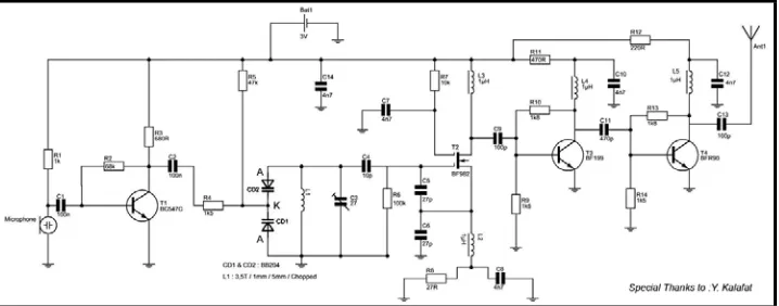
[image:21.595.141.500.145.286.2]2.2 3V FM Transmitter 88MHz to 108MHz by BF982
Figure 2.2: FM circuit with 3V transmitter by BF982
The important part of the circuit is formed of the Colpitts type oscillator.
C3, C4, C5, C6, CD1-CD2 and L1 determine the frequency. BF982 and dual
gate MOSFET are active parts in oscillator. When the input impedance of the
MOSFET gate inputs are high, LC tank is not affected. However transistors force
the LC tank and cause phase shift. [14]
Two driver stages are added to isolate the antenna from oscillator. First
stage (BF199) amplifies the low signal of the oscillator and works as a constant
load. The second stage (BFR90) amplifies the signal going through the antenna
some more. A short copper wire can be used as an antenna here. Attaching a
large antenna to this circuit is unnecessary because the output power is low. [14]
2.3 FM wireless Microphone Kit
Tiny FM Wireless Microphone Kit transmits every sound in a room to any
standard FM radio. Super sensitive kit uses a special high output electret
microphone and a two transistor circuit to provide a stable RF transmission.
Features adjustable capacitor to “fine tune” the frequency so that you can
transmit on a non-used part of the FM band. Use it as a baby monitor, one way
8
13/16” x 1” - the same size as a 9V battery. Complete with all parts, PC board
[image:22.595.245.427.165.289.2]and instructions.[15]
Figure 2.3: The FM wireless microphone kit.
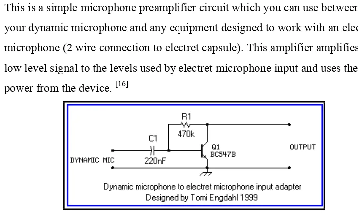
2.4 Dynamic microphone to electret microphone input.
This is a simple microphone preamplifier circuit which you can use between
your dynamic microphone and any equipment designed to work with an electret
microphone (2 wire connection to electret capsule). This amplifier amplifies the
low level signal to the levels used by electret microphone input and uses the
[image:22.595.141.500.394.614.2]power from the device. [16]
Figure 2.4: The dynamic microphone.
The circuit is a simple one transistor amplifier to convert the sub-millivolt level
voltage from electret microphone to current changes as generated by electret
9
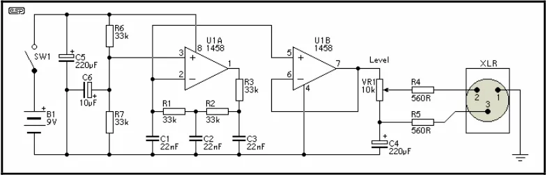
2.5 Microphone Circuit Test Oscillator
This unit would be mounted in a small plastic or preferably metal box,
with a 9V battery, level control, a male XLR connector (same as on a mic) and a
switch. Current drain is low, since the circuit only uses one dual op-amp. There
[image:23.595.122.518.232.358.2]is no need for a high quality device, and a 1458 is all that is needed.[17]
Figure 2.5 - Mic Circuit Test Oscillator
The first stage is the oscillator itself. This is a simple three stage phase
shift oscillator - a circuit that is remarkably uncommon - which is to say I have
never seen it used elsewhere. I designed it for another project a few years ago,
and I don't understand why it is not in any opamp application notes. [17]
If you want to tune it, you can use a 50k pot instead of R1. I suggest that
if tuned, set it to A-440 Hz. Frequency stability is not wonderful, and it changes
by a few Hertz as the battery discharges, but this is unlikely to cause problems -
it is a test oscillator, not a tuning standard. As shown, frequency will be about
430Hz, depending on the accuracy of the capacitors. [17]
The phase shift network (R1-C1, R2-C2 and R3-C3) serves two
purposes. First (and for an oscillator, most importantly), it shifts the phase of the
output signal so the feedback is positive, causing oscillation. Secondly, since it
is a three stage filter, it attenuates the signal and filters the output square wave so
10
about 3% or so - I didn't measure it this time, but I recall having done so before.
[17]
The second stage is the output buffer, and the signal is simply split to
supply the two mic leads. The metal case should be connected to pin 1 (earth) on
the XLR connector. The output level control must be a linear type, as the circuit
loading will create a good approximation to a log pot. Maximum output into a
typical microphone input will be about 100mV (unloaded oscillator output on
mine was 140mV). [17]
Not much to it - the whole circuit can be built on a small piece of Vero
board, and the battery, pot and XLR connector will take up far more room than
the oscillator. There is no LED indicator for power, as this would draw more
current than the circuit. To prevent accidentally turning it on, a slide switch is
suggested. They are a pig to mount compared to a toggle switch, but are much
less easily bumped. If you can get a pot with a switch, this would be even better,
but these are now hard to get - especially as linear. [17]
2.6 Wireless microphone system for high quality sound.
2.61 Filed of Invention
The present invention relates to a wireless receiving/transmitting
microphone system, and more particularly to a multi-channel, high quality audio
wireless microphone system in a local wireless communication area ensuring