PORTABLE WATER LEVEL INDICATOR
MUHAMMAD SYAFIQ BIN YUSUF
This Report Is Submitted In Partial Fulfillment Of Requirement For The Bachelor Degree of Electronic Engineering (Industrial Electronic)
Fakulti Kejuruteraan Elektronik dan Kejuruteraan Komputer Universiti Teknikal Malaysia Melaka
ii
“I hereby declare that this report is the result of my own work except for quotes as cited in the references.”
iii
“I hereby declare that I have read this report and in my opinion this report is sufficient in terms of the scope and quality for the award of Bachelor Degree of
Electronic Engineering (Industrial Electronic)”
iv
v
ACKNOWLEDGEMENT
It’s grateful to Allah S.W.T because with His blessing, I am able solve my problems. I am also thankful for my parent for their support, help, and guidance through all this long process.
vi
ABSTRACT
vii
ABSTRAK
viii
TABLE OF CONTENTS
CHAPTER TITLE PAGE
PROJECT TITLE DECLARATION
SUPERVISOR’S DECLARATION DEDICATION
ACKNOWLEDGEMENT ABSTRACT
ABSTRAK
TABLE OF CONTENTS LIST OF FIGURES LIST OF TABLES
LIST OF ABBREVIATIONS LIST OF APPENDICES
i ii iii iv v vi vii viii xi xiii xiv xv
I INTRODUCTION
1.1 PROJECT BACKGROUND 1.2 PROBLEM STATEMENT 1.3 PROJECT OBJECTIVE 1.4 SCOPE OF PROJECT 1.5 METHODOLOGY 1.6 THESIS OUTLINE
ix
II LITERATURE REVIEW
2.1 VOLTAGE REGULATOR 2.2 POWER SUPPLY CIRCUIT 2.3 SENSING OF WATER
2.4 TRANSMISSION AND RECEPTION 2.5 PIC MICROCONTROLLER
2.6 CRYSTAL OSCILLATOR
2.7 LIGHT EMITTING DIODE (LED) 2.8 BUZZER
2.9 RELAY 2.10 DIODE 2.11 CAPACITOR 2.12 PROJECT OUTPUT 2.13 OVERALL OPERATION
6 7 8 9 11 12 13 14 15 15 16 17 19
III METHODOLOGY
3.1 INTRODUCTION
3.2 FLOW CHART FOR PROJECT DEVELOPMENT 3.3 FLOW CHART FOR HARDWARE
DEVELOPMENT
3.4 FLOW CHART FOR SOFTWARE DEVELOPMENT
3.5 PIC16F877A
3.6 WIRELESS SYSTEM MODULE 3.7 PROJECT SCHEDULE
x
IV RESULT AND DISCUSSION
4.1 CIRCUIT CONSTRUCTION
4.2 CONSTRUCT THE PRINTED CIRCUIT BOARD (PCB) USING PROTEUS
4.2.1 Circuit PIC16F877A 4.2.2 Circuit Transmitter 4.2.3 Circuit Receiver
4.3 BUILD THE PRINTED CIRCUIT BOARD (PCB) 4.3.1 Printing The Circuit Layout
4.3.2 Expose 4.3.3 Develop 4.3.4 Etching 4.3.5 Drilling 4.4 RESULT
30 32 32 34 35 36 36 36 37 37 38 38
V CONCLUSION AND RECOMMENDATION
5.1 CONCLUSION
5.2 RECOMMENDATION
xi
LIST OF FIGURES
NO. TITLE PAGE
1.1 2.1
Block diagram for Portable Water Level Indicator IC LM7805
3 7
2.2 Power supply circuit 7
2.3 2.4
Conductor and insulators Radio Frequency module
9 10
2.5 PIC microcontroller pin 11
2.6 PIC16F877A 12
2.7 2.8 2.9 2.10 2.11 2.12 3.1 3.2 3.3 3.4 Crystal Oscillator
Light Emitting Diode (LED) Buzzer
Relay Diode
Type of capacitor
Flow chart for project development Flow chart for water sensor operation Flow chart for output operation Programming flow chart
13 14 14 15 16 16 21 23 24 25 3.5 Block diagram of PIC16F877A 26 3.6
3.7
Wireless system module Gantt chart of project planning
xii
4.1 Transmitter circuit on breadboard 31 4.2
4.3 4.4 4.5
Receiver circuit on breadboard PIC microcontroller circuit on ISIS PIC microcontroller circuit on ARES PIC microcontroller circuit PCB layout
31 32 33 33 4.6 4.7
Transmitter circuit on ARES Transmitter circuit PCB layout
34 34 4.8
4.9
Receiver circuit on ARES Receiver circuit on PCB layout
35 35 4.10 Transmitter and receiver circuit printing layout 36
4.11 Ultra Violet machine 36
4.12 Develop machine 37
4.13 Etching machine 37
4.14 Drilling activity 38
4.15 Transmitter PCB view from top 39 4.16
4.17 4.18
Receiver PCB view from top
Circuit PIC microcontroller view from top Portable water level indicator front view
xiii
LIST OF TABLES
NO. TITLE PAGE
2.1 Function each components in power supply circuit 8 2.2
2.3 3.1 4.1
List output project consist Standard LCD character table PIC16F877A pin assignment Stage of output condition
xiv
LIST OF ABBREVIATIONS
PIC - Programmable Integrated Circuit LCD - Liquid Crystal Display
LED - Light Emitting Diode RF - Radio Frequency TX - Transmitter RX - Receiver
AM - Amplitude Modulation FM - Frequency Modulation A/D - Analog to Digital Converter WTD - Watchdog Timer
DC - Direct Current PCB - Printed Circuit Board
xv
LIST OF APPENDICES
NO. TITLE PAGE
A PIC Microcontroller Pin 45
B C D
HT12 Encoder Pin HT12 Decoder Pin
Pin Radio Frequency Module
CHAPTER I
INTRODUCTION
This chapter consists of background study, objective, problem statement, scope of project, and methodology.
1.1 Project Background
Our country has two kinds of seasons. There are drought season and rainy season [1][2]. The rainy season might destroy human lives and things that are valuable to us. It happens when the water level increase to the danger level under controlled.
2
The natural phenomena such as heavy rainfall are the main factor that causing flood. The human factor is also the major problem that contributing flood. The human factor that caused the flood situation comes from uncontrolled development, effect of urbanization, inadequate drainage infrastructure, obstruction in the river by solid waste and garbage and development of flood plains [4][5]. Most of the victim of flood did not realize when the flood happened because the flood is unexpected phenomena if the public do not alert with the current situation of surroundings and weather.
1.2 Problem Statement
Flood in Malaysia are regular natural disaster which happen nearly every year during the monsoon season. Most floods that occur are a natural result of cyclical monsoon during the tropical wet seasons that are characteristic by heavy and regular rainfall. That is the major cause of flooding in Malaysia. Other than that, this flood problem is probability occur to residents whose lives at flooding area [6].
In fact, it is become dangerous to whole resident in the area especially to children and sometime cause death. Besides, it will cause big detriment such as assets destroyed, maintenance cost for electrical equipment and so on. It is also contribute traffic jam for closing the main road where the flood reached at high level. Hence, to avoid this problem, one project namely “Portable Water Level Indicator” will detect level of water (flood), thus preventing the water level to be more serious.
1.3 Project Objective
3
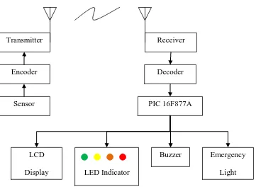
The aim of the portable water level indicator is to sense the accumulating water outside the house and the river depth. At the same time, the alarm will alert the user about the water level by using LCD and LED indicators. A buzzer will sound when the water level reaches a critical level determined by the user.
[image:19.595.155.516.306.573.2]The height of water that will be displayed by the LCD can be changed accordingly to the user’s need. The LED indicators will light up one by one according to the level of the water that is accumulating outside the house. Figure 1.1 shows the block diagram of portable water level indicator.
Figure 1.1: Block Diagram for Portable Water Level Indicator
1.4 Scope of Project
The scope of this chapter has been identified and it way divided into three parts which are:
Transmitter
Encoder
Sensor
Receiver
Decoder
PIC 16F877A
LCD
Display LED Indicator
Buzzer Emergency
4
i) Transmission of signal
Relate the used of Radio Frequency (RF) to the sensor, LCD, LED, buzzer, and emergency lights.
ii) Program code
Design a program code using Programmable Integrated Circuit (PIC) microcontroller that will control the whole system’s operation.
iii) Hardware and software
Design and test circuit using PROTEUS and compile coding using C-programmer.
1.5 Methodology
There are several methods to achieve the objectives. Firstly, literature research the RF communication and PIC microcontroller. Secondly, understand the function of each component to be used in the production, type of material use and improvement of this project. Lastly, collect the information based on the simulation of the designed circuit using PROTEUS and MULTISIM software.
1.6 Thesis Outline
5
Second chapter for this report is literature review. This chapter is divided into a few of sub chapter that will explain everything related to the flood detector, radio frequency and also previous work or design from other researchers. The basic concept and the principle of this metamaterial part will be show in this chapter.
Next chapter is methodology part. This part will explain about some of the guidelines for this project and also clearly mentioned steps that should be taken for this project. It show the step to achieve the main objective in this report.
The fourth chapter is the result and discussion. This part will cover about the results obtained for this project, and also discuss the results obtained. The result will be simulated using MULTISIM and PROTEUS software.
CHAPTER II
LITERATURE REVIEW
In this chapter, the overview of several fields that is involved in this report will be discussed. Design and building a portable water level indicator requires high knowledge of the input volatage supply to circuit a portable water sensor; water sensing ability, communication protocols, alarm output and others. This chapter discusses elaborately the system designs as they have been implemented in the final system design.
2.1 Voltage Regulator
7
Figure 2.1: IC LM7805
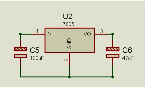
2.2 Power Supply Circuit
[image:23.595.192.451.557.711.2]Power supply circuit is the most importance circuit to make sure the overall component can be function. In this project, voltage source come from the 9V battery, LM7805 (1A maximum) will regulate the given voltage to 5V for supplying power to the PIC 16F877A, diode UF4001 is used in this circuit to protect the circuit if the connection for voltage source in wrong polarity. The capacitors are used to stabilize the voltage input and output of the LM7805. Figure 2.2 shows the power supply circuit and description for each components in power supply is shown in Table 2.1.
8
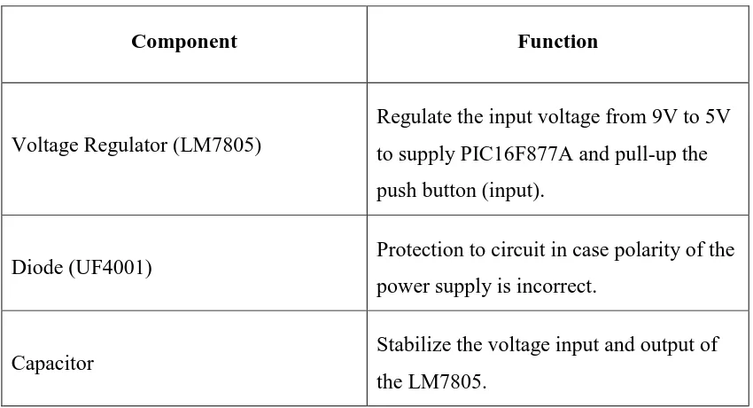
Table 2.1: Function Each Component in Power Supply Circuit.
2.3 Sensing of Water
The sensors used in this project are made of conductors with high conductivity. Conductivity is the measure of the ease at which an electric charge or heat can pass through a material. A conductor is a material which gives very little resistance to the flow of an electric current or thermal energy. Materials are classified as metals, semiconductors, and insulators. Metals are the most conductive conductors and insulators (ceramics, wood, plastics and etc) the least conductive. Figure 2.3 show a commonly conductor and insulator used.
Component Function
Voltage Regulator (LM7805)
Regulate the input voltage from 9V to 5V to supply PIC16F877A and pull-up the push button (input).
Diode (UF4001) Protection to circuit in case polarity of the power supply is incorrect.