World Applied Sciences Journal 21(Special Issue of Engineering and Technology): 01-10, 2013 ISSN 1818-4952
© IDOSI Publications, 2013
DOI: 10.5829/idosi.wasj.2013.21.1001
Corresponding Author: Lokman Abdullah, Faculty of Manufacturing Engineering, Universiti Teknikal Malaysia Melaka (UTeM), Hang Tuah Jaya,
Evaluation on Tracking Performance of PID, Gain Scheduling and Classical
Cascade P/PI Controller on XY Table Ballscrew Drive System
Lokman Abdullah, Zamberi Jamaludin, Qumrul Ahsan, Jailani Jamaludin,
1 1 1 1
Nur Aidawaty Rafan, Chiew Tsung Heng, Kamaruzaman Jusoff and Mariana Yusoff
1 1 2 3
Faculty of Manufacturing Engineering, Universiti Teknikal Malaysia Melaka (UteM), 1
Hang Tuah Jaya, 76100 Durian Tunggal, Melaka, Malaysia
Faculty of Forestry, Universiti Putra Malaysia, 43400 UPM Serdang, Selangor, Malaysia 2
Centre for Languages and Human Development, Universiti Teknikal Malaysia Melaka (UteM), 3
Hang Tuah Jaya, 76100 Durian Tunggal, Melaka, Malaysia
Abstract: Today, positioning systems in machine tools aim for high accuracy and robustness characteristics in order to accommodate against various disturbance forces. The objective of this paper is to evaluate the tracking performance of PID, Gain Scheduling and Cascade P/PI controller with the existence of disturbance forces in the form of cutting forces. Cutting force characteristics at different cutting parameters; such as spindle speed rotations is analysed using Fast Fourier Transform. The tracking performance of a classical cascade controller in presence of these cutting forces is compared to the PID controller and gain scheduling PID controller. Robustness of these controllers in compensating different cutting characteristics is compared based on reduction in the amplitudes of cutting force harmonics using Fast Fourier Transform. It is found that the cascade controller performs better than both PID controller and gain scheduling PID controller. The average percentage error reduction between cascade controller and Gain Scheduling controller is about 88% whereas the average percentage error reduction between cascade controller and Gain Scheduling controller is about 84% at spindle speed of 1000 rpm spindle speed rotation. The finalized design of cascade controller could be utilized further for machining application such as milling process. The implementation of cascade P/PI in machine tools applications will increase the quality of the end product and the productivity in industry by saving the machining time. It is suggested that the range of the spindle speed could be made wider to accommodate the needs for high speed machining.
Key words: Robust Control % Tracking Performance % Cutting Forces % Disturbance Compensation
INTRODUCTION material and the cutter geometry are chosen carefully to High tracking accuracy and precision are two vital shock that might result from these physical interactions components required in the manufacturing process. A [1]. These forces are natural consequences of the cutting good example of machining application is milling process and could not be avoided. For performance operation where a work piece is fed past a rotating purposes, the ability of the system to withstand these cylindrical tool with multiple cutting edges. Both of these forces and its impact will determine the standard and components are paramount important because it will lead quality of the end product to be manufactured.
depth of cut and spindle speed. Variations in these cutting conditions will affect behaviour of the cutting forces in terms of its magnitudes and its harmonics content. Failure to realise this phenomenon could reduce the quality of the finished product as the cutting forces may cause vibration of the structure thus leading to a poor surface roughness measurement. Hence, an
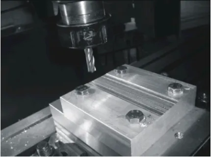
efficient and reliable compensation technique is desired Fig. 1: Googoltech XY milling table ballscrew drive in order to improve the tracking performance in machine system
tools applications. Previous researches on several compensation methods and approaches are discovered and have shown promising results; for example, Inverse Model Based Disturbance Observer [6], classical cascade controller [7] and Repetitive Controller [8,9] and based on the familiar PID control. Result based on PID controller [5] shows that the tracking error can be trim down until millimeter point only whereas results based on [8,9] show that the tracking error is reduced up to micron meter level via direct drive xy table. Furthermore, it is found that most of the research work were based on dedicated cutting forces and did not consider changing of the spindle speed. As a result, there is a need to conduct a
research based on various spindle speed. In this research Fig. 2: Milling operation performed for the purpose of work, the controller designed is based on this needs in collection of cutting force data.
which the spindle speed is varied.
METHODS Panasonic MSMD 022G1U A.C. servo motors
Test Setup: Figure 1 shows the ball-screw driven XY encoder for positioning measurement. The resolution milling table of an XYZ-Stage produced by Googol Tech. of the encoder is 2500 pulse/ rev with screw pitch of 5 mm The XY milling table consists of two axes namely; x and y and multiple frequencies of 4. In other words, the axes, driven by two Panasonic MSMD 022G1U A.C. servo resolution of the encoder is 0.0005 mm/pulse. Two limit motors respectively. Both axes are equipped with an switches are located in the near end of both axes. The incremental encoder for positioning measurement. The total mass of x-axis is 36.8 kg while the total mass of resolution of the encoder is 2500 pulse/rev with screw the y-axis is 23.4 kg.
pitch of 5 mm and multiple frequencies of 4. In other Figure 2 shows the milling process during the words, the resolution of the encoder is 0.0005 mm/pulse. collection of disturbance cutting force data. The Two limit switches are located in the near end of both aluminium block is placed on top of the Kistler axes. The total mass of x-axis is 36.8 kg while the total Dynamometer. The diameter of the milling cutter is 10mm. mass of the y-axis is 23.4 kg. The XY milling table The depth of cut is 0.5mm with the feed rate of
consists 502 mm/min.
of two axes namely; x and y axes, driven by two respectively. Both axes are equipped with an incremental
-60 -40 -20 0 20 40
Magnitude (dB)
101
102 -360
-270 -180 -90
Phase (deg)
Bode Diagram
Frequency (Hz)
frdFRF
Best Fit Model
-50 0 50
Magnitude (dB)
101 102
-270 -225 -180 -135 -90 -45
Phase (deg)
Bode Diagram
Gm = 9.23 dB (at 169 Hz) , Pm = 40.2 deg (at 70.7 Hz)
Frequency (Hz)
2
( ) 69380
( ) 144.8 166.3
Y s
U s =s + s+
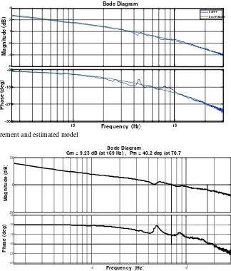
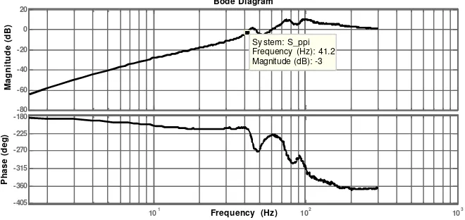
Fig. 4: FRF measurement and estimated model
Fig. 5: Bode Diagram of open loop system with PID control
Figure 3 shows a schematic diagram of the overall samples per window is 4096. The H1 estimator is system. The XY milling table is linked to a servo amplifier applied in estimating the FRF of the system. The input which is then connected to a DS1104 DSP board. A voltage, V in unit volt, U from excitation signals and personal computer, equipped with ControlDesk and output encoder measurement, Y in unit mm are recorded. MATLAB software is linked to the DSP board to apply Figure 4 shows the Bode diagram of the measured FRF control design and data collection. and the model transfer function of the system for the x-System Identification of XY Milling Table: By using the square frequency domain identification method [11,12] experimental setup in Figure 3, the system identifications through the frequency domain identification toolbox in are conducted on both x-axis and y-axis of the XY milling MATLAB.
table. The system dynamic is described as single-input- The second order transfer function is in continuous single-output (SISO) model. Band-limited white noise domain, S with time delay of 0.0013 seconds in which Y is signal is used to excite the system in order to measure the the output and U is the input signal. The model is as frequency response function (FRF) of the system. The follows:
sampling frequency is 2000 Hz and the duration of
measurement is 5 minutes. A Hanning window is used to (1)
reduce leakage on measurement [10] and the number of
-40
Fig. 6: Bode diagram of close loop system with PID control
Fig. 7: General structure of a gain scheduling controller Design of Controller 1 (PID Controller): Three different controllers are designed and their performance against cutting force acting as disturbance input signal are analysed. Analyses are performed using the plant transfer function (1). A Proportional Integral Derivative (PID) controller is a generic controller widely used in industrial control systems. The PID control equation involves three separate parameters, Proportional, Integral and Derivative terms.
(2) The controller parameters, kp, ki and kd are designed based on the phase margin and gain margin requirements of the open loop system. Figure 5 and 6 show the open loop and closed loop transfer function of the system with PID control. The gain margin of the open loop system is recorded at 9.23 dB while the phase margin is 40.2 degree. The result obtained authenticate with the rule of thumb design requirement of gain margin to be within the range of 3 to 10 dB and phase margin of 40 to 60 degree. Nyquist plot of the open loop transfer function verify the stability of the system, that is, the point [-1,0] is not encircled.
Table 1: Parameters of the look-up table
Spindle Speed (rpm) Kp Ki Kd
1000 1.3250 0.0004525 0.0067970
2000 1.2651 0.0005998 0.0057835
3000 1.2398 0.0006343 0.0057798
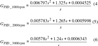
The PID transfer function is therefore,
(3) Design of Controller 2 (Gain Scheduling PID Controller): Gain scheduling control belongs to the nonlinear group of controllers. A gain scheduling controller based on PID control is designed. Figure 7 shows a general structure of a gain scheduling controller [13]. Table 1 lists the parameters of the look-up table.
The Gain Scheduling transfer function for each respective spindle speed are as follows,
(4)
(5)
-20 0 20 40
Magnitude (dB)
101 102
-270 -225 -180 -135 -90 -45
Phase (deg)
Bode Diagram
Gm = 9.94 dB (at 195 Hz) , Pm = 50.6 deg (at 72.3 Hz)
Frequency (Hz)
-1 -0.9 -0.8 -0.7 -0.6 -0.5 -0.4 -0.3 -0.2 -0.1 0
-10 -5
0 5
10 Nyquist Diagram
Real Axis
Imaginary Axis
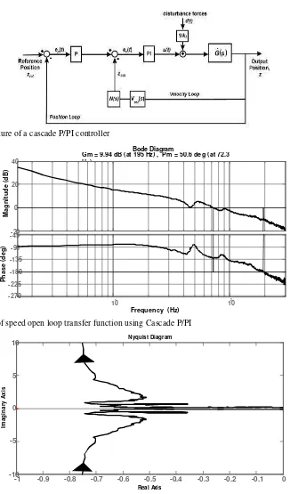
Fig. 8: Basic structure of a cascade P/PI controller
Fig. 9: Bode plot of speed open loop transfer function using Cascade P/PI
Fig. 10: Nyquist plot of open loop position transfer function using Cascade P/PI
101 102 103
Fig. 11: Bode plot of position sensitivity transfer function using Cascade P/PI
Table 2: List of the control parameters of the cascade P/PI controller
Parameters Values
K (velocity loop)p 0.0326 [volts.s]
K (velocity loop)i 0.0015 [volts.??2]
K (position loop)v 282sG1
Force-voltage converter 1/1623.49 N/V
RESULTS AND DISCUSSION
The measured cutting forces are inserted prior to the system (as illustrated in Figure 8) as disturbance cutting forces. The tracking performance of the PID, gain scheduling controller and the cascade P/PI controller are analysed and compared based on their robustness against different cutting conditions. Analyses on magnitudes of the harmonic components of the error signal and analyses on maximum position tracking errors are performed in order to quantify the compensation performance of these controllers against external cutting forces. Table 3 compares the harmonic amplitudes of the position error signal recorded between PID, Gain Scheduling and Cascade P/PI controllers at varying spindle speed rotations. As anticipated, the cascade P/PI controller produces improved performance compared to the classical PID and Gain Scheduling controller. The results appeared to concur as cascade controller has higher system bandwidth compared to the PID and Gain Scheduling controller.
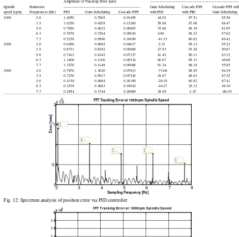
Harmonic Components of Tracking Errors: Figures 12-14 show the spectrum analyses of the position errors obtained using PID, Gain Scheduling and Cascade P/PI at 1000 rpm spindle speed rotation. The detailed results of the spectrum analyses of the position errors for each respective controller for the case of 2000 and 3000 rpm spindle rotation are tabulated in Table 3. Results
show an improved performance using cascade P/PI compared to both PID and Gain Scheduling controllers. The amplitude tracking error drops from 1.4050 µm at 2.0 Hz of PID controller to 0.7865 µm of Gain Scheduling controller. This result demonstrates an improvement of about 44 percent. A smaller improvement from 0.7670-0.7294 µm is recorded at the 4 harmonic frequency.th
However, due to its conservative design, the performance of the gain scheduling control drops beyond its bandwidth at 40.2 Hz. This performance indicates the limitation of the existing control design. Results show that cascade P/PI controller is able to compensate and reduce tracking error components generated from the cutting forces. Its performance is only limited by the control bandwidth. The cascade P/PI controller still maintains good performance even at a high harmonics frequencies region.
2 3 4 5 6 7 8
FFT Tracking Error at 1000rpm Spindle Speed
Error [mm]
FFT Tracking Error at 1000rpm Spindle Speed
X:
Table 3: FFT Analyses on harmonic components of the position errors
Error Reduction [%]
Amplitude of Tracking Error [µm]
---Spindle Harmonic --- Gain Scheduling Cascade P/PI Cascade P/PI with
speed [rpm] Frequencies [Hz] PID Gain Scheduling Cascade P/PI with PID with PID Gain Scheduling
1000 2.0 1.4050 0.7865 0.03495 44.02 97.51 95.56
3.5 1.0250 0.4205 0.13260 58.98 87.06 68.47
5.0 0.7650 0.4922 0.08883 35.66 88.39 81.95
6.3 0.7670 0.7294 0.09024 4.90 88.23 87.62
7.7 0.5239 0.9500 0.10050 -81.33 80.82 89.42
2000 2.0 0.9456 0.9665 0.04617 -2.21 95.12 95.22
3.5 0.8731 0.6292 0.05869 27.93 93.28 90.67
5.0 0.7412 0.4342 0.07327 41.42 90.11 83.12
6.3 1.1800 0.1100 0.05534 90.67 95.31 49.69
7.7 1.3270 0.1148 0.05068 91.34 96.18 55.85
3000 2.0 0.7870 1.3620 0.07913 -73.06 89.95 94.19
3.5 0.7276 0.5917 0.07545 18.67 89.63 87.25
5.0 0.4130 0.4964 0.16180 -20.19 60.82 67.41
6.3 0.2539 0.3663 0.19010 -44.27 25.12 48.10
7.7 0.2854 0.1744 0.28960 38.89 -1.47 -66.05
Fig. 12: Spectrum analysis of position error via PID controller
2 3 4 5 6 7 8 0
0.5 1 1.5 2 2.5 3 3.5 4 4.5
5x 10 -4
X: 2.11 Y: 0.0001313
Sampling Frequency [Hz]
Error [mm]
FFT Tracking Error at1000 rpm Spindle Speed
X: 3.5 Y: 0.0001326
X: 4.907 Y: 8.883e-005
X: 6.298 Y: 9.024e-005
X: 7.704 Y: 0.0001005
Fig. 14: Spectrum analysis of position error via cascade P/PI controller
Fig. 15: Trend of FFT tracking error between PID, Gain Scheduling and Cascade P/PI
Corresponding Trend of Tracking Errors at Different REFERENCES Spindle Speed: Figure 16 shows the trend of tracking
errors of Cascade P/PI controller at 1000, 2000 and 3000 rpm spindle speed rotation. The reason why the tracking errors at multiple spindle speed rotation was tabulated for Cascade P/PI only is simply because the performance of Cascade controller is better than the other controllers. Furthermore, the purpose of constructing Figure 16 is to recommend the best cutting condition in order to obtain the best result from the cascade controller in term of the lowest tracking error achieved. The result portrays that in order to acquire the best result; it is recommended to perform the machining operation at 2000 rpm spindle speed rotation since the lowest tracking errors occurred at this point of cutting condition. In addition, it is observed that the cascade P/PI is no longer frequency independent at 3000 rpm spindle speed rotation. This is due to the fluctuating pattern of cutting force characteristics that occurred naturally.
CONCLUSION
It can be concluded that Cascade P/PI controller performs better than both PID and Gain Scheduling controller. The maximum tracking errors of Cascade P/PI is approximately about 0.3 micron meter, while for the case of PID and Gain Scheduling controllers, the maximum tracking errors are 1.405 and 1.3620 micron meter respectively. Analyses on the harmonics content of the position tracking errors have shown the supremacy of cascade P/PI controller. The benefits of the implementation of cascade P/PI in machine tools applications are obvious in which it will increase the quality of the end product and the productivity in industry by saving the machining time. It is suggested that the range of the spindle speed could be made wider to accommodate the needs for high speed machining.
ACKNOWLEDGEMENT
This research is financially supported by the Fundamental Research Grants Scheme (FRGS), Ministry of Higher Education, Malaysia, with reference no. FRGS/2010/FKP/TK02/5 F00103 and the Faculty of Manufacturing Engineering, Universiti Teknikal Malaysia Melaka (UTeM), Malaysia.
1. Kalpakjian, S. and S. Schmid, 2006. Manufacturing Processes for Engineering, (3rd ed.). Addison Wesley: Longman.
2. Jamaludin, Z., H.V. Brussel, G. Pipeleers and J. Swevers, 2008. Accurate motion control of XY high-speed linear drives using friction model feedforward and cutting forces estimation. CIRP Annals-Manufacturing Technology, 57(1): 403-406. 3. Pritschow, G. and W. Phillip, 1992. Research on the
efficiency of feedforward controllers on machine direct drives. CIRP Annals-Manufacturing Technology, 41(1): 411-415.
4. Skogestad, S. and I. Posletthwaite, 2005. Multivariable Feedback Control-Analysis and Design, Chichester, West Sessex, England, John Wiley and Sons.
5. Wang, J., 2004. Robust tracking controller design with application to the motion control of an x-y feed table for high-speed machining, PhD Thesis, Faculty of Engineering, Department of Mechanical, Division of Production, Machine Design and Automation (P.M.A), Katholieke Universiteit Leuven, Belgium.
6. Jamaludin, Z., H.V. Brussel and J. Swevers, 2008. Quadrant glitch compensation using friction model-based feedforward and an inverse-model-based disturbance observer, Proceedings of International Conference on Advanced Motion Control, 26-28 March 2008, Centro Santa Chiarra Hotel, Trento, Italy.
7. Jamaludin, Z., H.V. Brussel and J. Swevers, 2007. Classical cascade and sliding mode control tracking performances for a x-y feed table of a high-speed machine tools, International Journal of Precision Technology, 1(1): 65-74.
8. Hara, S., Y. Yamamoto, T. Omata and M. Nakano, 1988. Repetitive control system: a new type servo system for periodic exogenous signals, IEEE Transactions on Automatic Control, 33(7): 659-668.
9. Pipeleers, G., B. Demeulenaere, J. DeSchutter and J. Swevers, 2008. Robust High-Order Repetitive Control: Optimal Performance Trade-Offs, Automatica, 44(9): 2628-2634.
11. Pintelon, R., P. Guillaume, Y. Rolain, J. Schoukens 13. Chih-Cheng, P., H. Thong-Shing, C. Shiaw-Wu, and H. Van Hamme, 1994. Parametric Identification of C. Ching-Yi, L. Yi-Ciao and W. Yao-Ting, 2010. Transfer Functions in the Frequency Domain-A ZPETC path-tracking gain-scheduling design and Survey. IEEE Transactions on Automatic Control, real-time multi-task flight simulation for the automatic 39(11): 2245-2260. transition of tilt-rotor aircraft. IEEE Conference on 12. Abdullah, L., Z. Jamaludin, T.H. Chiew, N.A. Rafan Robotics, Automation and Mechatronics, 28-30 June
and M.S. Syed Mohamed, 2012. System identification 2010, Waterfront Hotel, Singapore. of xy table ballscrew drive using parametric and non