Article
Effect of Transfer Layer on Ultra Low Friction of
CNx Coating under Blowing Dry Ar
Nor Azmmi Bin Masripan1,3)*, Yuki Miyahira1), Hidenori Nishimura1), Takayuki Tokoroyama1), Noritsugu Umehara1) and Yoshio Fuwa2)
1)
Advanced Materials & Manufacturing Laboratory, Department of Science and Engineering, Nagoya University Furo-cho, Chikusa-ku, Nagoya 464-8603, Japan
2)
Toyota Motor Co., Ltd.
1 Toyota-cho, Toyota, Aichi 471-8572, Japan 3)
Department of Mechanical Engineering, Universiti Teknikal Malaysia Melaka Hang Tuah Jaya, 76100, Durian Tunggal, Melaka, Malaysia
*Corresponding author: [email protected]
( Manuscript received 17 May 2012; accepted 18 April 2013; published 15 May 2013 )
In order to clarify the ultra low friction mechanism of Carbon Nitride (CNx) coatings under blowing dry Ar, thickness and area of transfer layers on mating surface were in-situ observed with an optical microscope during sliding against a sapphire hemisphere under blowing dry Ar. During sliding, thickness of transfer layer from CNx coating to a sapphire hemisphere increased and leaded to ultra low friction. When thickness and area of transfer layer was thick and small respectively, ultra low friction was observed. The result showed that the coefficient of friction decreased from 0.18 to 0.003 and remained constant throughout the friction test. It was confirmed the formation of a graphite-like transfer layer with Raman analysis and Auger Electron Spectroscopy (AES).
Keywords: CNx, dry Ar, blowing, ultra low friction, graphite-like transfer layer
1. Introduction
Carboneous hard coatings are used because those have good tribological properties, such as low friction, high hardness, and high wear resistance. Carbon Nitride (CNx) is expected as excellent materials with excellent tribological properties. CNx is a hybridized material that is composed of sp3 and sp2 Carbon-Nitrogen (C-N) bonding. CNx showed ultra low friction that is less than 0.01 of friction coefficient in dry Nitrogen gas [1]. The authors has tried to know the ultra low friction mechanism of CNx on the basis of surface analysis with Raman spectroscopy, XPS and AES because ultra low friction was observed after a number of repeated slidings in dry Nitrogen. As a result, we proposed the ultra low friction mechanism as the formation of thin graphite like layer that thickness is about 20 nm on the surface of CNx, the formation of transfer layer of graphite like wear particles and smoothing of friction surface [2]. However we have done the ex-observation after sliding test. Therefore we do not know the specific effect of the formation of transfer layer on the mating surface. In order to overcome this issue, we developed a friction tester with in-situ observation of transfer layer
under sliding against a sapphire hemisphere in different species of gas such as Argon (Ar), Nitrogen (N2) and ambient air.
In the case of ultra low friction under dry Nitrogen and dry Argon, friction coefficient decreased with the increasing of the thickness of transfer layer. On the other hand, friction coefficient did not decrease with the increasing of the thickness of transfer layer in the case under ambient gas [3]. These results show the transfer layer from CNx to mating surface has the essential role in the ultra low friction mechanism of CNx.
2. Experimental procedure
2.1. Test specimen
The Si(1 0 0) wafer disc was coated with a 100 µm thickness of CNx using Ion Beam Assisted Deposition (IBAD) method in this study. Further details of coating procedure can be seen in [4]. The Nitrogen content in the CNx is about 10%. A CNx surface roughness of 0.72 nmRa was measured using AFM. The hardness of the CNx coating was measured at approximately 25.2 GPa using nano indenter, with a maximum indentation load of 20 µN. A transparent sapphire hemisphere, with a radius of 4 mm, a hardness of about 35 GPa, and surface roughness of 30 nmRa, was chosen as a counter face.
2.2. Friction test
Figure 1 shows a ball-on-disc equipment with in-situ observation of contact point during sliding under blowing Ar gas. An electric motor was used to rotate the CNx coating, which was fixed on a rotatable disc holder, and the sapphire hemisphere was used as a stationary counter face at the upper side. The friction test was performed using the ball-on-disc tribometer, with a sliding speed of 83.8 mm/s, and a sliding track of 6 mm. The experiment was performed under ambient conditions, with room a temperature of 24°C and a relative humidity of about 26%. Dry Ar, with a 99.9999% purity, was used in this experiment. Dry Ar
came directly from the gas cylinder to the contact point between the CNx coating and the sapphire hemisphere, with a volume rate of 5 l/min throughout the sliding test. The O2 content and humidity were measured at sliding interface using TORAY Oxygen Analyzer (LC-750) and Thermo Recorder (TR-72U) in order to clarify the impurities of blowing Ar. A normal load of 0.1 N was applied constantly to the sapphire hemisphere with a leaf spring. The initial mean Herztian’s contact pressure was calculated at about 177 MPa, with a contact diameter of approximately 10 µm. The test’s specimens were cleaned in an ultrasonic bath in aceton for 15 minutes before and after the friction test, in order to avoid any contamination on the specimen surface during testing and other analysis.
Transfer layer formation phenomena during contact sliding, which was generated by friction between the transparent sapphire hemisphere and the CNx coating, can be observed with optical microscope using CCD camera, through the sapphire hemisphere. Newton’s ring can also be seen in the images and was used to estimate transfer layer thickness during the friction test. Pictures were taken every five cycles for 10,000 cycles.
2.3. Estimation of the thickness of transfer layer
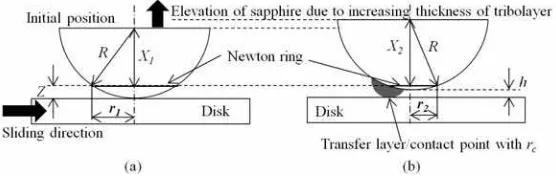
The transfer layer thickness can be estimated by comparing the Newton’s ring diameter images that were captured during the sliding test with an initial state image. The movement of Newton’s ring can be observed during the sliding test. Inward movements of Newton’s ring were caused by the elevation of the sapphire hemisphere, which corresponded to the increasing transfer layer thickness. The change of Newton’s ring diameter during sliding test can be observed and measured from the images. The use of Newton’s ring to quantify transfer layer thickness is given in [5,6]. Pythagoras theorem was used to estimate transfer layer thickness, as in Eq. (2), and referring to the schematic illustration of transfer layer formation, as shown in Fig. 2.
(
2) (
1)
h= y + −Z y +Z (1)
2 2 2 2
2 1
h= R − −r R −r (2)
where h is the transfer layer thickness; R is the radius of the sapphire hemisphere; Z is the height between the measured Newton’s ring from the contact surface; y1,2 are Fig. 1 Test rig based on the pin-on-disc method. A
combination of optical microscope and CCD camera were used to observe the in-situ frictional behaviour of the CNx coated disc against the sapphire hemisphere
the height between the top of the sapphire hemisphere and the Newton’s ring (1: before sliding, and 2 during sliding); r1,2 is the estimated radius of Newton’s ring (1: before sliding, and 2: during sliding).
2.4. Raman and AES analyses
The Raman spectra was obtained using a Jasco Laser Raman spectrophotometer NRS-1000 equipped with a second harmonic Nd:YAG laser with a maximum laser power and wavelength of 10 mW and 532 nm, respectively. However, only 1% of the maximum power was applicable for the measurement without burning the surface and also to avoid the influence of the substrate underneath. The AES (ULVAC PHI-650) was used to obtain the depth profiles of chemical composition of test specimen with beam energy of 5 kV and a probe current of 100 nA. Before the measurement, the test specimen surface was cleaned by ion sputtering with a sputtering energy and a probe current of 3 kV and 25 mA, respectively.
3. Results and Discussion
3.1. Effect of the thickness of transfer layer on friction coefficient
Figure 3 shows the coefficient of CNx coating against the sapphire hemisphere during the repeated sliding test under blowing dry Ar, as a function of the number of cycles. At approximately 300 cycles, the friction coefficient increased from 0.1 to 0.18. Then at 1000 cycles, the friction coefficient decreased drastically from 0.18 to 0.003. After a short running-in period, the friction coefficient was consistently ultra low until 10,000 cycles. Figure 4 shows images of transfer layer through a transparent sapphire hemisphere in each sliding cycles from 0 to 10,000 cycles.
The other experimental results show that the friction coefficient increased suddenly, due to a detachment of the transfer layer from the contact surface, as shown in
Fig. 5. Later, the transfer layer built-up again at the contact point, and the friction coefficient decreased slowly until it achieved a super low friction again. The images in Fig. 4 show that the initial real contact point was at the centre (zero cycle), but later it deviated to the front of the sliding direction (400 cycles), where it remained for the rest of the sliding test, as illustrated in Fig. 2.
Figure 4 shows the microscope images of Newton’s rings that formed around the contact point of the two surfaces (i.e., the sapphire hemisphere and the CNx coating) with different diameters and light intensities. The Newton’s rings were formed due to interference between the light waves reflected from the top and bottom surfaces.
Fig. 3 (a) The frictional behaviour of CNx coating against the sapphire hemisphere, as a function of sliding cycles and (b) transfer layer thickness as a function of sliding cycles under blowing Ar gas, contact load:0.1 N, and sliding speed: 83.8 mms-1
Fig. 5 (a) Sudden increase of friction coefficient during sliding between CNx coatings against Sapphire hemisphere as a function of sliding cycles (b) Images of transfer layer and Newton’s ring
The Newton’s ring’s diameters were measured and used to estimate transfer layer thickness using Eq. 2 from Pythagoras` theorem. The Newton’s ring becomes smaller due to the elevation of the sapphire hemisphere corresponding to the formation of a transfer layer at the contact point, as illustrated in Fig. 2. The results show that the friction coefficient decreased whilst the transfer layer thickness increased. See Fig. 3(a). In addition, the higher rate of transfer layer generation (about 0.092 nm/cycle) was seen from the beginning of sliding test during the running-in period until approximately 2000 cycles. Then, the transfer layer generation rate became lower (at about 0.046 nm/cycle) from 2000 cycles onwards, and the friction coefficient reached a super low friction of 0.003, where it remained until 10,000 cycles. An ultra low friction of 0.003 was achieved when the transfer layer thickness was around 60 nm after 1000 sliding cycles. The transfer layer thickness increased consistently to 550 nm at 10,000 cycles, whilst the friction coefficient kept constant at super low. The higher rate of transfer layer generation during the running-in period showed that more graphitization occurred then, than the steady state period. This result indicates that more wear debris was produced from sliding at the beginning, due to the direct surface contact between the sapphire hemisphere and the coating disc. The wear debris accumulated at the sliding contact and became a thin transfer layer through compaction. As the transfer layer became thicker, the wear rate of the CNx coating decreased because the transfer layer could act as a protective layer to reduce wear.
3.2. Effect of area of transfer layer and contact pressure on friction coefficient
As shown in Fig. 4, the initial image of the dark circle at zero cycles shows the direct contact point between the sapphire hemisphere and the CNx coating. At the beginning of friction test, the contact between the sapphire hemisphere and the CNx coating forming the Hertzian’s contact as shown in Fig. 4 at 0 and 200 cycles. However, from 400 cycles of sliding rotation, transfer layer was generated, and the contact point moved from centre to the front side of the sliding direction. At this point, there was no more Hertzian’s contact. The accumulation of wear debris at contact interface segregated the direct contact between sapphire hemisphere and CNx coating. The measured contact radius, rc decreased from 0 to 10000 cycles around 13 µm initially to 4 µm (10000 cycles). The changing contact radii were measured carefully from the captured images using CCD to be used later for the estimation of contact area, A. The measured radius of the Hertzian’s contact point was 13µm at initially state (i.e., zero cycles), which was confirmed by calculating the contact radius of 10 µm using Hertzian’s contact mechanics; as per Eq. 4 [7]. The different values, between measured and calculated Hertzian’s contact point radii, are due to inaccurate measurements of the contact point using
optical images. It is very difficult to obtain accurate value of Hertzian’s contact radius by measurement because of the blurring of the contact edge as shown in Fig. 4 (0 cycles). The difference between the measured contact point radius, rc and the calculated Hertzian’s contact radius, a was within a few micrometres, and are also reported elsewhere [6].
* hemisphere’s radius, E* is the effective elastic modulus, ν1, and ν2 are the Poisson’s ratio of the sapphire hemisphere and the CNx, respectively, and E1, and E2 are the Young’s modulus of the sapphire hemisphere and the CNx, respectively. A measured contact point radius was used to calculate the mean pressure Pm using Eq. 6.
m
Where, rc is the measured contact radius.
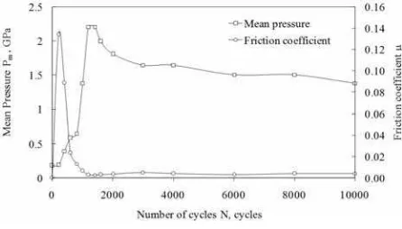
Figure 6 shows the relation between the estimated mean contact pressure and the friction coefficient, as a function of sliding cycles. The contact pressure increased drastically from 0.174 to 2.25 GPa, where the friction coefficient was shown to decrease to a super-low level of 0.003 until 10,000 cycles of rotation. Then, the contact pressure decreased slowly from 2.25 to 1.5 GPa. The friction coefficient achieved a steady state condition at around 0.003, when the pressure was at a high value of around 1.5 GPa.
Another essential relation shown in this study is how the estimated mean Herztian’s contact pressure affects the generation of the transfer layer as shown in Fig. 7. The transfer layer’s thickness increased with different rates i.e., during the running-in period and after the running-in period, with 0.092 nm/cycle and 0.046
nm/cycle, respectively. The transfer layer formation rate become higher by increasing of the Herztian’s mean pressure during the running-in period up to 2000 cycles, and it became lower when the contact pressure remained at a high value of around 1.5 GPa from 2000 to 10,000 cycles.
3.3. Phase transition of CNx coating at sliding contact interfaces
Like DLC, CNx is a material with a combination of sp3 and sp2 carbon bonds, which the nitrogen substitutes into the sp2-bonded ring to a saturation level of about one nitrogen to every three carbon atoms. This CNx structure provides good tribological properties, such as low friction, high hardness, and high wear resistance. CNx graphitization occurred when desorption of nitrogen atoms from the CNx matrix was caused by raising the annealing temperature. Generally, the transition temperature of CNx is about 200ºC, which corresponds to a sp3-sp2 transition temperature [8]. However, during sliding, the transition temperature can be decreased to a lower value, due to the high contact stress [9,10]. The CNx transition temperature can be calculated according to the Clapeyron law [11], with the functions of contact pressure and specific volume of low and high nitrogen contents of carbon nitride, as per Eq. 7.
exp
c
T T p
L
ν
⎛− ∆ ⎞
= ⎜⎜ ∆ ⎟⎟
⎝ ⎠ (7)
Where Tc is the critical phase transition temperature of CNx (200°C) [8], ∆v is the difference between specific volume of low nitrogen content (0.303 × 10⁻³ m3/kg3) and high nitrogen content (0.746 × 10⁻³ m3/kg3) [12], and ∆p is the difference between Herztian’s contact pressure and atmospheric pressure. As explained previously, the contact area decreased throughout the sliding test, corresponding to increased contact pressure. Fig. 8 shows that the phase transition temperature of CNx coatings decreased with an increase of Herztian’s contact pressure at the sliding interface. Hence, a high contact
pressure results in a lower transition temperature sp3-sp2 of CNx, to as low as 20°C. This explains that the graphitization process possibly occurred under high contact stress at room temperature, since the experiment was performed under room temperature (about 24°C).
3.4. Ex-observation of wear track with Optical
microscope (OM), Raman spectroscopy and Auger Electron Spectroscopy (AES)
After the sliding test, the CNx coating and sapphire hemisphere was observed using SEM and an optical microscope. Fig. 9(a) shows a picture of the compacted wear debris along the wear track on the CNx coating after the sliding test. No wear debris was found within the wear track because the wear debris was ejected outside of the wear track during the sliding. The generated transfer layer was transferred from the coating surface to the sapphire hemisphere’s surface. The microscope image shows that the transfer layer is strongly adhered to the sapphire hemisphere, as shown in Fig. 9(b).
Figure 10(a)-(d) show the Raman spectra of the as-deposited wear track, the transfer layer, and the wear debris, respectively. The Raman spectra shape, of the as-deposited of CNx, is comparable to other researcher’s results [13]. The shape of Raman spectra on the wear track, after the sliding test, was the same as the
Fig. 7 Relation between the estimated mean Herztian’s constant pressure and transfer layer thickness, as a function of sliding cycles
Fig. 9 (a) SEM observation of the wear track and debris on the CNx coating disc after the sliding test. (b) Microscope image of the transfer layer on the sapphire hemisphere, after the sliding test
as-deposited CNx; with the same Raman shift, G peak of 1576.5 1/cm. However, the Raman shifts of the G peak for both the wear debris and transfer layer show a different value of 1588.8 1/cm. This shifting G peak value, from a low to a higher frequency, means that transition of sp3-sp2 (also known graphitization) occurred during the sliding test [14].
The Raman shape of the wear debris and the transfer layer is comparable with pure graphite, as reported by other researchers [15]. This means that the graphitic material was removed from the CNx coating’s wear track and accumulated as a transfer layer; which then adhered to the sapphire hemisphere and partially became wear debris.
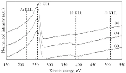
Figure 11(a)-(c) show the results for Ar KLL, C KLL, N KLL, and O KLL peaks through AES analysis, between 150 and 550 eV on as-deposited CNx, wear track and wear debris, respectively. The kinetic energy of Ar KLL, C KLL, N KLL, and O KLL were approximately 220, 258, 374, and 510 eV, respectively. The intensity of the N KLL peaks on the wear debris is approximately zero. This means that there was no N content in the wear debris compared to the as-deposited CNx, and the wear track. This proves that desorption of N from the CNx coating during sliding was responsible for the graphitization process. Under high pressure stress, the C-N sp2 bonds tend to release their N content to become a more stable graphite-like structure [9,11].
AES analysis does not detect the Ar content on the wear track or the debris after the sliding test. This means that the Ar gas, as an inert gas, was not involved in the tribochemical reaction with the dangling bonds [16]; which probably influenced the tribological performance. Oxygen molecules were not found on the coating surface, both before and after the sliding test. No oxidation process occurred on the coating surface before, during, or after the friction test, that influenced the results of the sliding test and the analysis.
3.5. Effect of transfer layer on ultra low friction of CNx coating
An ultra low friction level of 0.003 was observed during the sliding test, between the CNx coatings against the sapphire hemisphere, under blowing dry Ar gas directly onto the contact interface. In-situ observation confirmed that the generation of transfer layer at the contact point was responsible for reducing the friction coefficient to a super low level. It was also observed that the friction coefficient increased at the beginning of the friction test (up to 300 cycles), then the friction coefficient dropped to an ultra-low level of 0.18 to 0.003 at 1000 cycles. Sharp asperities that broke-off at the CNx coating’s surface interface, which contributed to the nano particles, caused the increasing friction coefficient at the beginning of the sliding test. It is believed that the formation of the transfer layer began after 300 cycles, by the compaction of nano wear particles between the CNx coating and the sapphire hemisphere. Accumulation of the transfer layer at the contact surface completely separated the contact between the CNx coating and the sapphire hemisphere. This provided a steady state value of super low friction between 1000 to 10,000 cycles. The transfer layer thickness was calculated and a significant relation between the friction coefficient and the transfer layer was found, which with a constantly increasing transfer layer, drops the friction coefficient to a lower level. Super low friction can be achieved at a steady state through a sufficiently thick transfer layer at the contact interface, where it will remain throughout the sliding test. Fig. 3 shows that a steady state of super low friction of 0.003 was achieved at 1000 cycles, with a sufficient transfer layer thickness of 60 nm. Further consistent increments of the transfer layer do not affect the friction coefficient anymore.
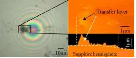
Figure 12 shows the ex-situ observation of the transfer layer on the sapphire hemisphere using AFM, after the sliding test. The thickness of the transfer layer was measured at approximately 550 nm. This value is comparable with that calculated at the end of the sliding
Fig. 10 Raman spectra of (a) as-deposited (b) wear track on the CNx coating (c) transfer layer on the sapphire hemisphere, and (d) wear debris on the CNx coating
test of 10,000 cycles, as discussed in Section 3.1. The transfer layer thickness is much higher than the RMS value of of 3 nm for the CNx coating and the sapphire hemisphere. It is believed that a steady state of super low friction was not influenced further by surface properties, such as the surface roughness of the CNx coatings and the sapphire hemisphere after 1000 cycles, but was fully controlled by the transfer layer; as long as the transfer layer was attached to the contact interface [17]. The Raman spectra of the transfer layer and the wear debris, as shown in Fig. 10, proved that the transfer layer had graphite-like structures, which contributed to the super low friction during the friction test [18,19]. AES analysis showed that no Ar molecule was found on the test specimen after the sliding test. As an inert gas, the function of Ar is to protect accessibility of water and oxygen molecules from the environment to the sliding interface, which subsequently prevents chemical reaction that can cause an increment of friction coefficient [16]. Fig. 13 shows the in-situ observation of relative humidity and O2 content at the sliding interface during the sliding test. The relative humidity reduces significantly from 25 to 6% after 1 minute. In addition, the O2 content reduced drastically from 20 to 0.2% after the Ar gas blew directly to the sliding contact interface. The very low value of relative humidity and O2 was consistent throughout the sliding test. The influence of relative humidity and O2 on friction coefficient is considered very minimum in this experiment. High humidity and oxygen can cause high friction during friction test, as reported elsewhere [3,16,19]. As an inert gas, dry Ar gas flowed into the disorderly graphite structure without involving chemical interaction which attributed to the passivation of dangling covalent bonds [16]. This caused the atomic displacements from disorder into inter-lamellar layer of the lattice, which provided a highly slippery layer for super low friction, as reported elsewhere [19]. Since, no transfer layer was attached to the wear track of the CNx coating and the strongly adherent surface of the transfer layer on the sapphire hemisphere, it is suggested that a super low friction mechanism on the CNx coating against the sapphire hemisphere was provided by a low shear strength between the graphite-like transfer layer and the CNx coating.
4. Conclusions
In-situ observation successfully identified the transfer layer generation, which contributed to the friction behaviour of the CNx coating against the sapphire hemisphere. From this study, the following conclusions can be made:
1. The transformation of CNx to graphite-like transfer layer is a consequence of high contact pressure 1.5 GPa at the contact interface.
2. The desorption of N content from the CNx coating during sliding was responsible for graphitization. 3. The shape of Raman spectra of the transfer layer is
comparable with pure graphite.
4. Existing of a graphite-like transfer layer with the thickness of 60 nm between the CNx coating and the sapphire hemisphere, will significantly reduce the friction coefficient to an ultra low of 0.003.
The permanent attachment of a transfer layer at the contact interface is very important to maintain an ultra low friction during the friction test.
References
[1] Kato, K., Umehara, N. and Adachi, K., “Friction, Wear and N2-Lubrication of Carbon Nitride Coatings: A Review,” Wear, 254, 11, 2003, 1062-1069.
[2] Umehara, N., Tatsuno, M. and Kato, K., “Nitrogen Lubricated Sliding between CNx Coatings and Ceramic Balls,” Proceedings of the International Tribology Conference, Nagasaki, 2000, 1007-1012.
[3] Miyahira, Y., Tokoroyama, T. and Umehara, N., “Effect of Atmosphere Gas on Ultra Low Friction Properties of CNx Coating,” The Japan Society of Mechanical Engineers, 10, 2010, 47-48 (In Japanese).
[4] Tokoroyama, T., Goto, M., Umehara, N., Nakamura, T. and Honda, F., “Effect of Nitrogen Fig. 12 Microscope and AFM images of the transfer
layer on the sapphire hemisphere
Atoms Desorption on the Friction of the CNx against Si3N4 Ball in Nitrogen Gas,” Tribology Letters, 22, 3, 2006, 215-220.
[5] Chromik, R. R., Baker, C. C., Voevodin, A. A. and Wahl, K. J., “In Situ Tribometry of Solid Lubricant Nanocomposite Coatings,” Wear, 262, 9-10, 2007, 1239-1252.
[6] Wahl, K. J., Chromik, R. R and Lee, G. Y., “Quantitative In Situ Measurement of Transfer Film Thickness by a Newton's Rings Method,” Wear, 264, 7-8, 2008, 731-736.
[7] Johnson, K. L., “Contact Mechanics,” Cambridge University Press, Cambridge, 1987, 93.
[8] McCulloch, D. G. and Merchant, A. R., “The Effect of Annealing on the Structure of Cathodic Arc Deposited Amorphous Carbon Nitride Films,” Thin Solid Film, 290-291, 1996, 99-102.
[9] Zhou, Z. F., Li, K. Y., Bello, I., Lee, C. S. and Lee, S. T., “Study of Tribological Performance of ECR-CVD Diamond-Like Carbon Coatings on Steel Substrates Part.2: The Analysis of Wear Mechanism,” Wear, 258, 10, 2005, 1589-1599. [10] Haque, T., Morina, A., Neville, A., Kapadia, R.
and Arrowsmith, S., “Effect of Oil Additives on the Durability of Hydrogenated DLC Coating under Boundary Lubrication Conditions,” Wear, 266, 1-2, 2009, 147-157.
[11] Huu, T. Le, Zaidi, H., Paulmier, D. and Voumard, P., “Transformation of sp3 to sp2 Sites of Diamond Like Carbon Coatings during Friction in Vacuum and under Water Vapour Environment,” Thin Solid Films, 290-291, 1996, 126-130.
[12] Hu, J., Yang, P. and Lieber, M., “Nitrogen-Driven sp3 to sp2 Transformation in Carbon Nitride
Materials,” Physical Review B, 57, 6, 1998, 3185-3188.
[13] Tokoroyama, T. and Umehara, N., “Effect of Nitrogen Atom Included in CNx Coatings on Friction Sliding against Si3N4 Ball in Nitrogen Gas,” International Symposium on Micro-Nano Mechatronics and Human Science, 2007, 586-591. [14] Liu, Y., Erdemir, A. and Meletis, E. I., “A Study of the Wear Mechanism of Diamond-Like Carbon Films,” Surface and Coatings Technology, 82, 1-2, 1996, 48-56.
[15] Reich, S. and Thomsen, C., “Raman Spectroscopy of Graphite,” Phil. Trans. R. Soc. Lond.A, 362, 2004, 2271-2288.
[16] Sánchez-López, J. C., Belin, Donnet, C., M., Quiró, C. and Elizalde, E., “Friction Mechanisms of Amorphous Carbon Nitride Films under Variable Environments: A Triboscopic Study,” Surface and Coatings Technology, 160, 2-3, 2002, 138-144. [17] Scharf, T. W. and Singer, I. L., “Tribology of
Diamond-Like Carbon Films: Fundamental and Applications,” Springer, 2008, 201-236.
[18] Zaidi, H., Robert, F. and Paulmier, D., “Influence of Adsorbed Gases on the Surface Energy of Graphite: Consequences on the Friction Behaviour,” Thin Solid Films, 264, 1, 1995, 46-51.