STUDY OF HEAT EXCHANGER EFFECT IN A CAR AIR CONDITIONING SYSTEM
NUR FASIHA BINTI NAZIRMUIDIN
I/ We have read this thesis and from my/out opinion this thesis
is sufficient in aspects of scope and quality for awarding Bachelor of Mechanical Engineering (Thermal-Fluid)
Signature :……….
Name of supervisor :……….
STUDY OF HEAT EXCHANGER EFFECT IN A CAR AIR CONDITIONING SYSTEM
NUR FASIHA BINTI NAZIRMUIDIN
A project report submitted in partial fulfillment of the requirements for the award of Degree of Bachelor Mechanical Engineering (Thermal-Fluid)
Faculty of Mechanical Engineering Universiti Teknikal Malaysia Melaka
“I hereby, declare this thesis is results of my own research accept as cited in references”
Signature :………
Author’s Name : NUR FASIHA BINTI NAZIRMUDIN
iii
ACKNOWLEDGEMENT
Firstly, I would to give my greatest gratitude and appreciation to my supervisor of this Projek Sarjana Muda (PSM), Encik Faizil bin Wasbari for his guidance, support and practical advisers throughout the entire project. I would also like to thanks to Encik Razmi bin A. Razak for his assistance and guidance contributed toward the success of the project.
ABSTRACT
v
ABSTRAK
TABLE OF CONTENTS
VERIFICATION ii
ACKNOWLEDGEMENT iii
ABSTRACT iv
ABSTRAK v
TABLE OF CONTENTS vi-ix
LIST OF FIGURES x-xiv
LIST OF TABLES xv-xvii
CHAPTER 1 : INTRODUCTION
1.1 Background Study 1
1.2 Problem Statement 1
1.3 Objectives 2
1.4 Scopes 2
CHAPTER 2: LITERATURE REVIEW
2.1 Introduction 3
2.2 Flow Arrangement 3
2.3 Types of Heat Exchanger 4-9
2.4 Car Air Conditioning 9-10
2.5 Car Air Conditioning Components 11-17
2.6 The Cooling System 18-20
vii
2.8 Selection of Heat Exchanger 21-22
2.9 Heat Exchanger Comparison 22-25
2.10 A chart for predicting the possible advantage of adopting a
suction/liquid heat exchanger in refrigerating system 25-29
2.11 Refrigeration system performance using liquid-suction
heat exchangers. 29-31
2.12 Evaluation of suction-line/liquid-line heat exchange
in the refrigeration cycle 31-34
CHAPTER 3: METHODOLOGY
3.1 Introduction 35
3.2 Literature Review 35
3.3 Conceptual Design 37
3.4 Selection of Heat Exchanger 37
3.5 Detail design and drawing 37
3.6 Selection of Material 37
3.7 Fabrication 38
3.8 Setup the components 38
3.9 Run the testing 38
3.10 Result 39
3.11 Data Analysis 39-40
CHAPTER 4: SELECTION OF DESIGN AND MATERIAL
4.1 Introduction 42
4.2 Selection of Design 42
4.3 Selection of Material 43-46
CHAPTER 5: DESIGN PROPOSAL AND DETAIL OF DESIGN
5.1 Introduction 48
5.2 Explanations of Design 48
5.3 Detail Drawing 49-54
CHAPTER 6: MODIFICATION AND PROCEDURE
6.1 Modification of Air Conditioning System 55-59
6.2 Procedure for the experiment 60
CHAPTER 7: RESULTS
ix
CHAPTER 8: DATA ANALYSIS
8.1 Heat exchanger effectiveness 79-82 8.2 refrigeration cycles on p-H diagram 82-88
8.3 Effects of heat exchanger on COP 88-89 8.4 Effect of fuel consumption for without heat exchanger
and different lengths of heat exchanger 89-90
CHAPTER 9: DISCUSSION
9.1 Effect different size heat exchanger on refrigeration system 91-93 9.2 Effect different sizes of heat exchanger in terms
of fuel consumption 93 9.3 Limitation during the experiment 93-94
CHAPTER 10: CONCLUSION AND RECOMMMENDATION
8.1 Conclusion 95
8.2 Recommendation for future works 96
REFERENCES 97-98
BIBLIOGRAPHY 99
LIST OF FIGURES
FIGURE TITLE PAGES
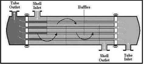
Figure 2.1: Shell and Tube Heat Exchanger
(Source: http//www.ra.danfoss.com/TechnicalInfo) 4 Figure 2.2: Conceptual diagram of a plate and frame heat exchanger.
(Source: http://en.wikipedia.org/wiki/heat_exchanger) 5
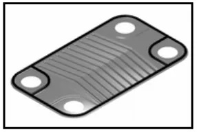
Figure 2.3: A single plate heat exchanger
(Source: http://en.wikipedia.org/wiki/heat_exchanger) 5
Figure 2.4: Tubular Heat Exchanger
(Source: http://en.wikipedia.org/wiki/heat_exchanger) 7
Figure 2.5 Car Air Conditioning Systems
(Source: http//:www.visteon.com 9
Figure 2.6: Compressor
(Source: http://images.search.yahoo.com/images/condenser) 11 Figure 2.7: Condenser
xi
Figure 2.8: Evaporator
(Source: http://images.search.yahoo.com/images/evaporator) 12
Figure 2.9: Orifice Tube
(Source: http//specialtauto.com/air-conditioning-systems) 13
Figure 2.10: Thermal Expansion Valve
(Source: http//specialtauto.com/air-conditioning-systems) 14
Figure 2.11: Receiver Drier
(Source: http//specialtauto.com/air-conditioning-systems) 14
Figure 2.12: Accumulator
(Source: http//specialtauto.com/air-conditioning-systems) 15
Figure 2.13: Heat Convection
(Source: www.vtaide.com/png/heat2_htm) 20
Figure 2.14: Heat Exchanger Tubular Reactor
(Source: www.elsevier.com/locate/cep) 23
Figure 2.15: Schematic refrigeration cycle adopting suction/liquid heat exchanger.
Figure 2.16: Thermodynamics transformation of a basic cycle with and without suction-liquid heat exchanger.
(Source: Mastrullo and Mauro (2007)) 27
Figure 2.17: The COP’/COP ratio for R-717 and R-134a, for various condensing temperature and evaporating temperature.
(Source: Mastrullo and Mauro (2007)) 28
Figure 2.18: Schematic of typical vapor-compression refrigeration cycle with liquid-suction heat exchanger
(Source: Klein (2000)) 29
Figure 2.19: Relative capacity index vs _hvap/(Cp,L Tc) for various temperature lifts for a liquid-suction heat exchanger with no pressure losses and effectiveness=1.0.
(Source: Klein (2000)) 31
Figure 2.20: Schematic of hardware arrangements for (a) the basic cycle and (b) cycle with liquid-suction line heat exchanger
(Source: Domanski and Didion (1994)) 32
Figure 2.21: Key refrigerant state point in basic cycle and LLSL-HX cycle. (Source: Domanski and Didion (1994) ) 33
Figure 3.1: Flow chart for methodology 36
xiii
Figure 3.3: p-H diagram 40
Figure 4.1: Graph of Thermal Conductivity (BTU.ft/h.ft2.F) versus Price (USD/lb)
(Source: CES Software (2005) 46
Figure 5.1: Isometric View for length 10 cm 49
Figure 5.2: Orthographic View for 10 cm 50
Figure 5.3: Isometric View for length 20 cm 51
Figure 5.4: Orthographic View for length 20cm 52
Figure 5.5: Isomeric view for length 30 cm 53
Figure 5.6: Orthographic view for length 30 cm 54
Figure 6.1: Suction hose 55
Figure 6.2: Insulation tape 55
Figure 6.3: Aluminum pipe 56
Figure 6.4: Aluminum tube 56
Figure 6.5: Hacksaw 56
Figure 6.6: Aluminum wire 56
Figure 6.7: Hose clip 57
Figure 6.10: Aluminum pipe after brazing process 58
Figure 6.11: The unwanted part of suction hose 58
Figure 6.12: Suction hose and liquid line. 58
Figure 6.13: Tighten of suction hose and liquid line by using aluminum wire 59 Figure 6.14: Complete modification of heat exchanger 59 Figure 7.1: Schematic of experimental system without heat exchanger 61 Figure 7.2: Schematic of experimental system with heat exchanger 66 Figure 8.1: Effectiveness versus rotational speed for heat exchanger 10 cm 80 Figure 8.2: Effectiveness versus rotational speed of heat exchanger 20 cm 81 Figure 8.3: Effectiveness versus rotational speed of heat exchanger 30 cm 82 Figure 8.4: p-H diagram for refrigeration cycle of 1000 rpm 84 Figure 8.5: p-H diagram for refrigeration cycle of 1500 rpm 85 Figure 8.6: p-H diagram for refrigeration cycle of 2000 rpm 86 Figure 8.7: p-H diagram for refrigeration cycle of 2500 rpm 87
Figure 8.8: COP versus Rotational speed (rpm) 88
xv
LIST OF TABLES
Table 2.1: Heat exchanger capability with their different reactor.
(Source: www.elsevier.com/locate/cep) 25
Table 4.1: Mechanical Properties for Aluminum alloys
(Source: CES Software (2005)) 44
Table 4.2: Thermal Properties for Aluminum alloys
(Source: CES Software (2005)) 44
Table 4.3: Mechanical Properties for Copper alloys
(Source: CES Software (2005) 45
Table 4.4: Thermal Properties for Copper alloys
(Source: CES Software (2005)) 45
Table 4.5: Selection of material 45
Table 7.4: Results for 2500 rpm without heat exchanger 65
Table 7.5: Results for 1000 rpm with heat exchanger 10 cm 67
Table 7.6: Results for 1500 rpm with heat exchanger 10 cm 68
Table 7.7: Results for 2000 rpm with heat exchanger 10 cm 69
Table 7.8: Results for 2500 rpm with heat exchanger 10 cm 70
Table 7.9: Results for 1000 rpm with heat exchanger 20 cm 71
Table 7.10: Results for 1500 rpm with heat exchanger 20 cm 72
Table 7.11: Results for 2000 rpm with heat exchanger 20 cm 73
Table 7.12: Results for 2500 rpm with heat exchanger 20 cm 74
Table 7.13: Results for 1000 rpm with heat exchanger 30 cm 75
Table 7.14: Results for 1500 rpm with heat exchanger 30 cm 76
Table 7.15: Results for 1500 rpm with heat exchanger 30 cm 77
Table 7.16: Results for 2500 rpm with heat exchanger 30 cm 78
xvii
Table 8.2: Results for effectiveness of heat exchanger 20 cm 80
Table 8.3: Results for effectiveness of heat exchanger of 30 cm 81
Table 8.4: Comparison enthalpy and COP for 1000 rpm 84
Table 8.5: Comparison enthalpy and COP for 1500 rpm 85
Table 8.6: Comparison enthalpy and COP for 2000 rpm 86
Table 8.7: Comparison enthalpy and COP for 2500 rpm 87
Table 8.8: Comparison COP with three different heat exchanger 88
Table 8.9: COP improving using the heat exchanger. 89
CHAPTER 1
INTRODUCTION
1.1 Background Study
Heat exchangers are common components in many everyday devices. Car engines, refrigerators, air conditioners, central heating boilers and radiators all contain heat exchangers. They are devices specifically designed for the efficient transfer of heat from one fluid to another fluid over a solid surface. This transfer of heat can either take the form of absorption or dissipation of heat. As a heat transfer device, it is the function of a heat exchanger to transfer heat as efficiently as possible. This makes it the ultimate device of choice, for instance, when it comes to saving energy by recovering wasted heat and making it useful again. When there is a waste of energy or a heat stream that is not recovered a heat exchanger can covert that heat stream into something that can be used.
1.2 Problem Statement
2
1.3 Objectives
i. To understand basic concept of car air conditioning system.
ii. To learn effect of different lengths heat exchanger to temperature and pressure in term of Coefficient of Performance (COP).
iii. To study effect heat exchanger on car fuel consumption.
1.4 Scope
CHAPTER 2
LITERATURE REVIEW
2.1 Introduction
Heat exchanger is a device built for efficient heat transfer from one medium to another, whether the media are separated by solid wall so that they never mix, or the media are in contact. Heat exchanger widely used in refrigeration, air conditioning, power plants, space heating, and natural gas processing. One common example of a heat exchanger is the radiator in car, which the heat source, being a hot engine-cooling fluid, water transfers heat to air flowing through the radiator.
2.2 Flow Arrangement
4
For efficiency, heat exchangers are designed to maximize the surface area of the wall between the two fluids, while minimizing resistance to fluid flow through the exchanger. The exchanger's performance can also be affected by the addition of fins or corrugations in one or both directions, which increase surface area and may channel fluid flow or induce turbulence.
2.3 Types of Heat Exchanger
2.3.1 Shell and tube heat exchanger
Figure 2.1: Shell and Tube Heat Exchanger (Source: http//www.ra.danfoss.com/TechnicalInfo)
2.3.2 Plate heat exchanger
Figure 2.2: Conceptual diagram of a plate and frame heat exchanger. (Source: http://en.wikipedia.org/wiki/heat_exchanger)

