FLUID AND HEAT FLOW PERFORMANCE IN HEAT EXCHANGER
NURLIYANA BINTI MOHD NADZRI
THIS DISSERTATION IS SUBMITTED IN PARTIAL FULFILLMENT OF THE REQUIREMENT FOR THE AWARD OF THE DEGREE OF
BACHELOR OF MECHANICAL ENGINEERING (THERMAL-FLUIDS)
Faculty of Mechanical Engineering Universiti Teknikal Malaysia Melaka
‘Saya/Kami* akui bahawa telah membaca karya ini dan pada pandangan saya/kami* karya ini
adalah memadai dari segi skop dan kualiti untuk tujuan penganugerahan Ijazah Sarjana Muda Kejuruteraan Mekanikal (Termal Bendalir)’
Tandatangan : ……… Nama Penyelia 1 : ... Tarikh : ...
Tandatangan : ... Nama Penyelia 2 : ... Tarikh : ...
“I declare that this report is done by my own exclude citation with the mentioned references for each.”
Signature : ………
Author : ……….
i ACKNOWLEDGEMENT
I would like to express my special thanks to my supervisor, Dr. Mohd Yusoff Bin Sulaiman for his advices, continual guidance and commitment in helping me doing the research. He always gives me the idea and knowledge in helping me to carry out the research in a better way. His knowledge is very useful for me to do the research appropriately.
ii ABSTRACT
iii ABSTRAK
iv TABLE OF CONTENTS
CHAPTER TITLE PAGE NUMBER
ACKNOWLEDGEMENT i
ABSTRACT ii
ABSTRAK iii
CONTENT iv
LIST OF TABLES vii
LIST OF FIGURES viii
LIST OF SYMBOLS xi
LIST OF APPENDICES xiii
CHAPTER I INTRODUCTION 1
1.1 Background of the study 1
1.2 problem Statement 2
1.3 Research Objective 3
1.4 Scope of the Study 3
CHAPTER II LITERATURE REVIEW 4
2.1 Introduction 4
2.2 Heat Exchanger 11
2.3 Mathematical Formulation 17
and Numerical Model
2.3.1 Governing Equations 17
2.3.2 Turbulence Model and 18
v 2.3.3 Relations for Surface and 19
Core Geometry
2.3.4 Air Flow 23
2.3.5 Fins 24
2.3.6 Tubes 26
2.4 Wind Tunnel 27
CHAPTER III METHODOLOGY 30
3.1 Introduction 30
3.2 Automotive heat exchanger experiments 30 3.2.1 Wind Tunnel Experiment 31 3.3 Fluid flow and heat transfer simulation 34
Using CFD
3.4 Calculation of the automotive heat 35 exchanger performance.
3.4.1 Calculation of heat transfer 35 3.4.2 Calculation of compact heat exchanger 35 3.4.3 Calculation for mass flow rate 36
3.4.2.1 Experimental method 36 3.4.2.2 Theoretical Method 36
3.5 Flow Chart 37
CHAPTER IV RESULT 39
4.1 Wind Tunnel Test
4.2 Calculation for existing radiator and new 42 design of radiator
vi 4.3.3 3D Flow - Circular Radiator 49
CHAPTER VI CONCLUSION & RECOMMENDATION 52
REFERENCE AND 53
BIBLIOGRAPHY
APPENDIX A 55
APPENDIX B 57
APPENDIX C 58
APPENDIX D 59
APPENDIX E 60
vii LIST OF TABLES
NO. TITLE PAGE NUMBER
3.1 Specification of APM radiator 59
3.2 Specification of Wira radiator 59
4.1 Data for Proton Wira radiator at 60°C 60
4.2 Data for Proton Wira radiator at 65°C 60
4.3 Data for APM radiator at 60°C 60
viii LIST OF FIGURES
NO. TITLE PAGE NUMBER
2.1 Radiator 5
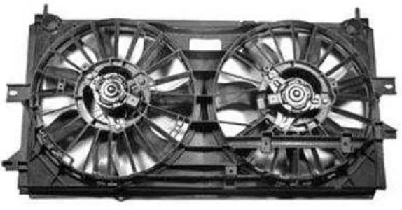
2.2 Radiator Fan 6
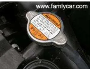
2.3 Pressure Cap 8
2.4 Water Pump 9
2.5 Thermostat 10
2.6 Radiator 11
2.7 Effect of inlet coolant temperature and volume 12 flow rate on heat dissipation
2.8 Effect of inlet coolant temperature and air velocities 13 on heat dissipation
2.9 Under hood air flow profiles in a typical passenger car 15
2.10 Discretisation strategy for flat tube/corrugated fin 23 automotive radiators; macro volume concept.
ix 2.12 Schematic diagram of one-tube plate fin heat exchangers 25
with the fin spacing.
2.13 Physical geometry of a two-dimensional annular circular 25 fin with measurement locations and sub-fin regions.
2.14 Nodes at the interface of two-neighboring sub-fin areas. 26
2.15 Schematic diagram of Wind Tunnel 28
2.16 The arrangements of electrodes 29
3.1 Schematic diagram of Wind Tunnel 32
3.2 Mounted radiator 32
3.3 Wind tunnel 33
3.4 Detail drawing of existing radiator 34
3.5 Detail drawing of circular radiator 35
4.1 Graph point of speed vs. velocity at temperature 39 60°C and 65°C for Wira radiator
4.2 Graph point of speed vs. volume flow rate at 40 temperature 60°C and 65°C for Wira radiator
4.3 Graph point of speed vs. velocity at temperature 41 60°C and 65°C for APM radiator
x
4.5 Existing radiator 43
4.6 Meshing cells 44
4.7 The square angle of meshing cells 44
4.8 Contours of velocity magnitude (m/s) 45
4.9 Velocity vectors by static temperature 46
4.10 Iterations chart 46
4.11 Circular radiator 47
4.12 Contours of velocity magnitude (m/s) 48
4.13 Contours of static temperature 48
4.14 Contours of velocity magnitude (m/s) 49
4.15 Side view of the 3D circular 50
xi LIST OF SYMBOLS
αa = Ratio of total heat transfer area of one side of the
exchanger to its volume, m2/m3 A = Total heat transfer area, m2
A0 = Free flow area of one side of exchanger, m2
Afr = Frontal area of one side of the exchanger, m2
B = Air flow length in the exchanger, m Ca = Stream heat capacity rate for air
p
c = Specific heat loss of coolant Cw = Stream heat capacity rate for water
C = Heat capacity rate ratio
C = Specific heat at constant dynamic viscosity ,
p a
C = Specific heat of air
= Heat exchanger effectiveness f = Friction factor
g = Gravity
a
G = Core mass velocity a
j = Multiplied factor of heat exchanger L = Length of each tube
p
L = Louver pitch c
m = Coolant mass flow rate ,
u w
N = Nusselt’s number
Q = Heat Loss
t
R = Ratio of the convection heat transfer characteristic to the convection mass
xii Re = Reynold’s number
h
r = Fin radius
Ti-T0 = Temperature Drop Ua = Air side area
V = Total volume of the exchanger, m3 a
W = Specific thermal resistance of air
= Water density
= Viscosity
t
= Viscosity in tube
xiii LIST OF APPENDICES
NO. TITLE PAGE NUMBER
A Gantt Chart 55-56
B Conventional Radiator 57
C Circular Radiator 58
D Table of Radiator Specifications 59
E Table of Results 60-61
1 CHAPTER I
INTRODUCTION
1.1 Background of the Study
A heat exchanger is a device built for efficient heat transfer from one medium to another, whether the media are separated by a solid wall so that they never mix, or the media are in direct contact. They are widely used in space heating, refrigeration, air conditioning, power plants, chemical plants, petrochemical plants, petroleum refineries, and natural gas processing. One common example of a heat exchanger is the radiator in a car, in which the heat source, being a hot engine-cooling fluid, water, transfers heat to air flowing through the radiator.
Heat exchanger maybe classified according to their flow arrangement. In parallel-flow heat exchanger, the two fluids enter the exchanger at the same end, and travel in parallel to one another to the other side. In counter-flow heat exchangers, the fluids enter the exchanger from opposite ends. The counter current design is most efficient, so that it can transfer the most heat. In a cross-flow heat exchanger, the fluids travel roughly perpendicular to one another through the exchanger.
2 temperature increases above a certain threshold value, the vehicle's thermostat triggers a valve which forces the coolant to flow through the radiator. As the coolant flows through the tubes of the radiator, heat is transferred through the fins and tube walls to the air by conduction and convection.
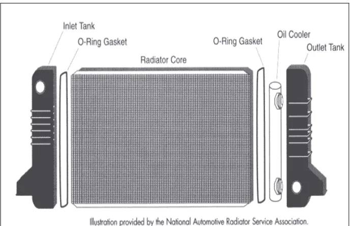
Depending upon the size of the engine and the cooling requirements, one, two, three or four cores can be used. There is also an inlet and outlet tank. These tanks hold the coolant before it goes into the radiator or into the block. The inlet tank also has a hose connection to allow coolant to flow from the engine into the radiator. The outlet tank has a hose connection to allow coolant pass back to the engine. In addition, there is a filler neck attached to one of the tanks. The radiator cap is placed here.
1.2 Problem Statement
In an automobile, fuel and air produce power within the engine through combustion. Only a portion of the total generated power actually supplies the automobile with power, the rest is wasted in the form of exhaust and heat. If this excess heat is not removed, the engine temperature becomes too high which results in overheating and viscosity breakdown of the lubricating oil, metal weakening of the overheated engine parts, and stress between engine parts resulting in quicker wear, among other things.
3
1.3 Research Objectives
The objectives of this research are:
i. To compare the performance of the existing heat exchanger with the new design of heat exchanger.
ii. To simulate 2D CFD flow of the design.
1.4 Scope of the Study
The scopes of the studies are:
i. Heat exchanger system that will be used to conduct the experiment will be the automotive radiator.
ii. Experiments will be conducted to compare the fluid and heat flow of the existing exchanger system with a new circular heat exchanger design.
4
CHAPTER II
LITERATURE REVIEW
2.1 Radiator
The radiator core is usually made of flattened aluminum tubes with aluminum strips that zigzag between the tubes. These fins transfer the heat in the tubes into the air stream to be carried away from the vehicle. On each end of the radiator core is a tank, usually made of plastic that covers the ends of the radiator,
5 Figure 2.1: Radiator
The tanks, whether plastic or brass, each have a large hose connection, one mounted towards the top of the radiator to let the coolant in, the other mounted at the bottom of the radiator on the other tank to let the coolant back out. On the top of the radiator is an additional opening that is capped off by the radiator cap. More on this later.
Another component in the radiator for vehicles with an automatic transmission is a separate tank mounted inside one of the tanks. Fittings connect this inner tank through steel tubes to the automatic transmission. Transmission fluid is piped through this tank inside a tank to be cooled by the coolant flowing past it before returning the transmission.
2.1.1 Radiator Fans
6 rising. On older systems, the fan was connected to the front of the water pump and would spin whenever the engine was running because it was driven by a fan belt instead of an electric motor. In these cases, if a driver would notice the engine begin to run hot in stop and go driving, the driver might put the car in neutral and rev the engine to turn the fan faster which helped cool the engine. Racing the engine on a car with a malfunctioning electric fan would only make things worse because you are producing more heat in the radiator with no fan to cool it off.
The electric fans are controlled by the vehicle's computer. A temperature sensor monitors engine temperature and sends this information to the computer. The computer determines if the fan should be turned on and actuates the fan relay if additional air flow through the radiator is necessary.
[image:22.595.170.457.522.672.2]If the car has air conditioning, there is an additional radiator mounted in front of the normal radiator. This "radiator" is called the air conditioner condenser, which also needs to be cooled by the air flow entering the engine compartment. You can find out more about the air conditioning condenser by going to our article on Automotive Air Conditioning. As long as the air conditioning is turned on, the system will keep the fan running, even if the engine is not running hot. This is because if there is no air flow through the air conditioning condenser, the air conditioner will not be able to cool the air entering the interior.
7 2.1.2 Pressure cap and reserve tank
As coolant gets hot, it expands. Since the cooling system is sealed, this expansion causes an increase in pressure in the cooling system, which is normal and part of the design. When coolant is under pressure, the temperature where the liquid begins to boil is considerably higher. This pressure, coupled with the higher boiling point of ethylene glycol, allows the coolant to safely reach temperatures in excess of 250 degrees.
The radiator pressure cap is a simple device that will maintain pressure in the cooling system up to a certain point. If the pressure builds up higher than the set pressure point, there is a spring loaded valve, calibrated to the correct Pounds per Square Inch (psi), to release the pressure.
8 Figure 2.3 : Pressure Cap
2.1.3 Water Pump
A water pump is a simple device that will keep the coolant moving as long as the engine is running. It is usually mounted on the front of the engine and turns whenever the engine is running. The water pump is driven by the engine through one of the following:
A fan belt that will also be responsible for driving an additional component like an alternator or power steering pump
A serpentine belt, which also drives the alternator, power steering pump and AC compressor among other things.
The timing belt that is also responsible for driving one or more camshafts.